Notice. New forum software under development. It's going to miss a few functions and look a bit ugly for a while, but I'm working on it full time now as the old forum was too unstable. Couple days, all good. If you notice any issues, please contact me.
renewableMark Guru Joined: 09/12/2017 Location: AustraliaPosts: 1678
Posted: 04:56am 02 Aug 2019
Copy link to clipboard
Print this post
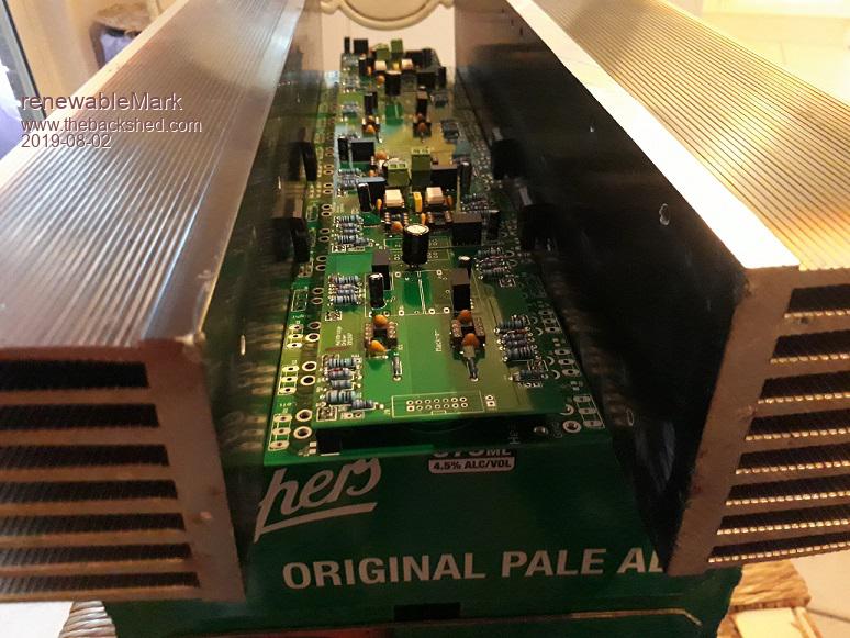
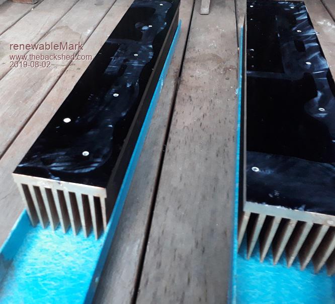
Not sure which way to jump here. I could align the heatsinks this way, but getting at the fixing bolts will be a bit fiddly.
Or it could be done this way.
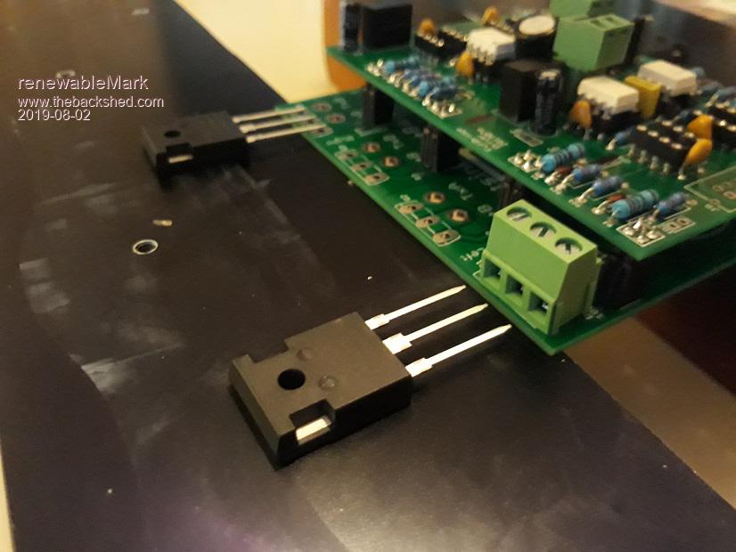
The fets could either be soldered in and the legs bent around (being careful not to stress the leg where it goes into the black body of the fet)
Or the 20A plugs could get used.Cheers Caveman Mark Off grid eastern Melb
Warpspeed Guru Joined: 09/08/2007 Location: AustraliaPosts: 4406
Posted: 05:56am 02 Aug 2019
Copy link to clipboard
Print this post
As you say, the top picture is going to be difficult to access the screws. Soldering in is not a good idea IMHO, and if you use screw terminal blocks in the top picture the screws on those will be even more difficult to reach.
I much prefer the lower picture. The screws are all facing straight up and you can see what you are doing with excellent access and visibility.
You could use conventional capacitor clamps to support the capacitors, then use the capacitor terminals to support the busbars and circuit boards.
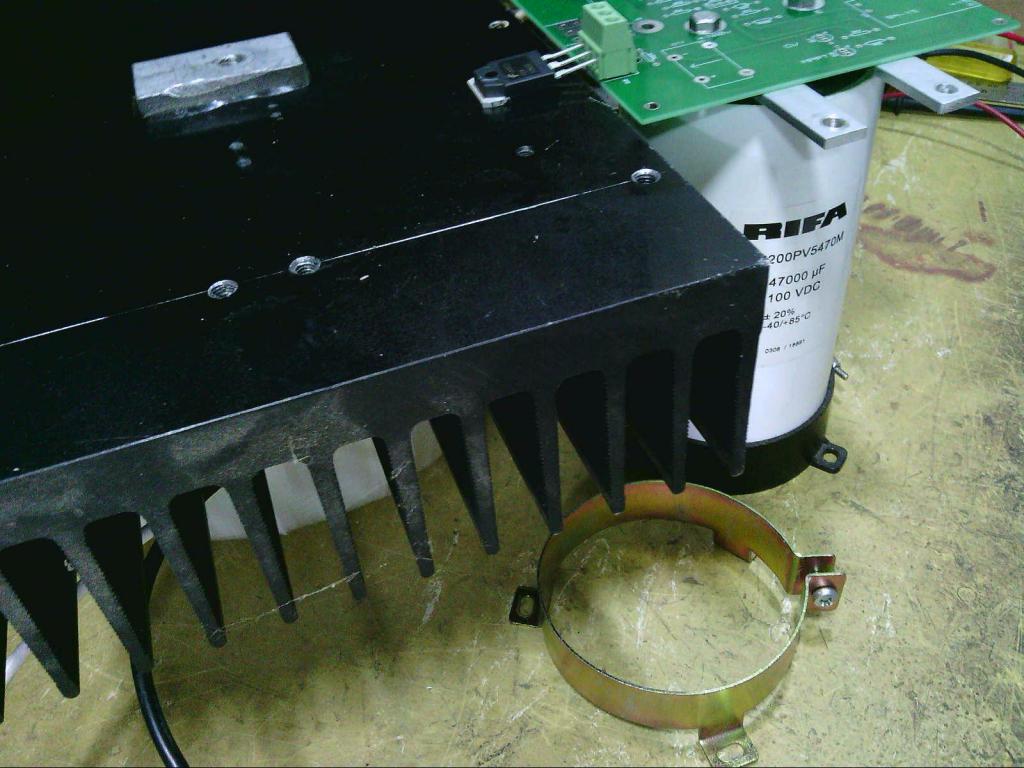
The mosfet legs can then bridge between the circuit board and heatsink, like this:
Cheers, ĀTony.
mackoffgrid Guru Joined: 13/03/2017 Location: AustraliaPosts: 460
Posted: 05:56am 02 Aug 2019
Copy link to clipboard
Print this post
I was always worried about bending the legs of the bigger devices. But, I do like the idea of the Mosfet being horizontal like in photo two.
Warpspeed Guru Joined: 09/08/2007 Location: AustraliaPosts: 4406
Posted: 06:26am 02 Aug 2019
Copy link to clipboard
Print this post
Thinking about this a bit more................
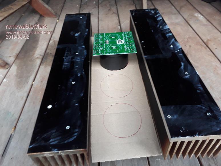
How about a big flat sheet of 3mm aluminium with a row of 75mm holes for the capacitors. The capacitor clamps can clamp around near the middle of the capacitors, and the height of the circuit board can be adjusted to perfection. The finned heatsinks bolt to the aluminium plate forming an air tunnel.
It would make a very rigid easy to fabricate structure, that ties everything together with everything very easy to work on.Cheers, ĀTony.
renewableMark Guru Joined: 09/12/2017 Location: AustraliaPosts: 1678
Posted: 07:07am 02 Aug 2019
Copy link to clipboard
Print this post
Like this?
I was thinking perspex, that way I won't need to worry about insulating the connections to heatsinks.
The caps aren't actually that heavy and the boards seem to support them just fine.
Anyway the initial idea was to use the fibreglass channel to tie it all in together.Cheers Caveman Mark Off grid eastern Melb
renewableMark Guru Joined: 09/12/2017 Location: AustraliaPosts: 1678
Posted: 07:19am 02 Aug 2019
Copy link to clipboard
Print this post
Turns out that fibreglass channel fits like a glove. I have 2 bits each a bit over 2 metres, so plenty to make up a solid frame.
Cheers Caveman Mark Off grid eastern Melb
Warpspeed Guru Joined: 09/08/2007 Location: AustraliaPosts: 4406
Posted: 07:19am 02 Aug 2019
Copy link to clipboard
Print this post
Yes exactly Mark.
The capacitor clamps may need to be located underneath the plate so you can get to the screws with the circuit board and busbars fitted.
I bolted (and epoxied) some aluminium angle to my heatsink, which then bolted down onto a big flat plate.
Cheers, ĀTony.
Warpspeed Guru Joined: 09/08/2007 Location: AustraliaPosts: 4406
Posted: 07:24am 02 Aug 2019
Copy link to clipboard
Print this post
Ah yes !!! I like that blue fibreglass channel, perfect
Perspex might be better too.Cheers, ĀTony.
renewableMark Guru Joined: 09/12/2017 Location: AustraliaPosts: 1678
Posted: 07:26am 02 Aug 2019
Copy link to clipboard
Print this post
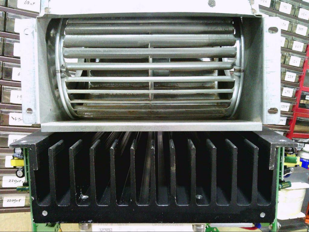
They will need a fan each, but the plus side id they will be baffled the same way you do with an aircraft (piston) engine, to get all the flow through the fins.
Caravan fridges work the same way, lots of air flowing all over the fins at the back doesn't cool them, restrict the flow (baffle) to just the fins seems to work best.Cheers Caveman Mark Off grid eastern Melb
Warpspeed Guru Joined: 09/08/2007 Location: AustraliaPosts: 4406
Posted: 07:42am 02 Aug 2019
Copy link to clipboard
Print this post
A computer fan is not going to be up to the job, the pressure drop along that long heat sink is going to be quite high at sufficient air volume.
One or two centrifugal air blowers wold be more suitable. I used a 230v blower from a Rinnai gas room heater, but a 12v car heater blower might have more suitable dimensions.Cheers, ĀTony.
Warpspeed Guru Joined: 09/08/2007 Location: AustraliaPosts: 4406
Posted: 08:08am 02 Aug 2019
Copy link to clipboard
Print this post
It will be more efficient, with a lower pressure drop if you feed the air blower into the middle of the heatsink, so that half the air goes up, and half the air goes down (onto the transformers). That is how I did mine.
Cheers, ĀTony.
BenandAmber Guru Joined: 16/02/2019 Location: United StatesPosts: 961
Posted: 08:10am 02 Aug 2019
Copy link to clipboard
Print this post
Wow mark wow!! Impressivebe warned i am good parrot but Dumber than a box of rocks
BenandAmber Guru Joined: 16/02/2019 Location: United StatesPosts: 961
Posted: 08:12am 02 Aug 2019
Copy link to clipboard
Print this post
Wow warp speedbe warned i am good parrot but Dumber than a box of rocks
Warpspeed Guru Joined: 09/08/2007 Location: AustraliaPosts: 4406
Posted: 08:45am 02 Aug 2019
Copy link to clipboard
Print this post
A good mechanical layout that is simple, neat, has very easy access, really good cooling, and is really pleasant to work on, is just as important as the detailed electronic design.Cheers, ĀTony.
renewableMark Guru Joined: 09/12/2017 Location: AustraliaPosts: 1678
Posted: 09:47am 02 Aug 2019
Copy link to clipboard
Print this post
Yes, I'm taking my time planning this one. I don't like how my other machine is crammed into a box, very inconvenient if something goes wrong. Thankfully the bugs seem to be ironed out of that though (just touched my wood desk )
The locker it's going in has two doors/sections, so they'll need individual fans anyway.
I already have some temp controlled circuits for the fans/heatsinks that are 12v so may as well stick with that for now. Might try the computer fans to see how the flow is, might end up with a car one, wait and see.
Other thing is that bus bar is 3.2mmx19mm. That won't be up to handling the power, might have to double it up.
@ Ben, don't go wow yet mate, nothing but a collection of parts so far.Cheers Caveman Mark Off grid eastern Melb
Warpspeed Guru Joined: 09/08/2007 Location: AustraliaPosts: 4406
Posted: 10:07am 02 Aug 2019
Copy link to clipboard
Print this post
That busbar will be 61 mm squared, in free air good for 300 amps + continuous. Even 12mm x 3.2mm would be more than enough if its copper.
My blower has seen some 42C+ days and has never come on, not even once. The vertical tunnel heatsink works pretty well without any forced air help.
Ran the inverter with about 3Kw load which included a 1.6Kw hot air gun that was aimed right through the heat sink. It took about 25 minutes for the heatsink to hit 45C. Its a massive chunk of aluminium. When the blower started up, it pulled it back to 40C in about two minutes. Its huge overkill, but I wanted something that I can definitely rely on.
Computer fans will probably be o/k, but if you really plan on 7.5Kw continuous for air conditioning, then it may need some help. Anyhow some real world testing will soon tell you.Cheers, ĀTony.
renewableMark Guru Joined: 09/12/2017 Location: AustraliaPosts: 1678
Posted: 10:33am 02 Aug 2019
Copy link to clipboard
Print this post
Yeah that bar is copper, well that's good it will be up to the task, thanks.
Both air cons running would only pull 3.5kw plus a few appliances around the home.
We aren't actually terribly big consumers, I never tell my wife not to use stuff, or go crook at her when there are 10 lights on, but we just don't seem to use all that much, it's only a small house after all and the roof has been insulated like hell.
I wanted something big so it could handle the horrible load the inverter air con places on it. The mad inverter runs it OK but it distorts the sine pretty bad, same with the microwave.
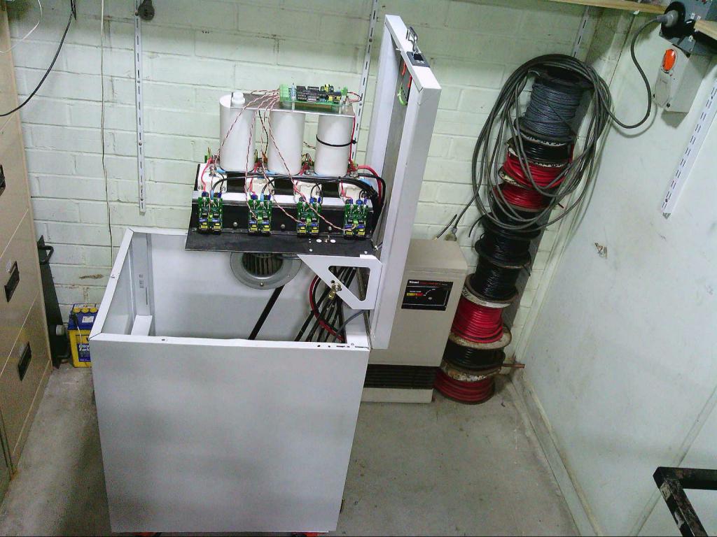
Other thing that got changed to the plan is all 4 inverters will run the Mack boards now. This will add two Mack power boards with their full driver boards.
The little half driver boards would have saved some space, but if the cap capacity needs to be increased it will be far easier if there are two more mounting points already sitting there. If that did happen then there would be 6 caps with a total of 300,000uf, it currently has 4 caps, total of 200,000uf. It may not need it but it will save a lot of time doing it this way if it does.Cheers Caveman Mark Off grid eastern Melb
mackoffgrid Guru Joined: 13/03/2017 Location: AustraliaPosts: 460
Posted: 12:12pm 02 Aug 2019
Copy link to clipboard
Print this post
Mark, something to think about is how to fix the Fets to the heatsink. If you fix the Fets directly to the large heatsink you have an awful lot of 3mm taps to do, I know you've done this before. If you use an aluminium bar, say 6mm x 50mm, you can nut and bolt the mosfets to that and fix the bar to the heatsink using a couple of either 6mm or 8mm bolts going into tapped holes of the heatsink. The 8mm bolts double as the connection points for the battery lug etc. 8mm taps into aluminium are much easier than 3mm taps.
Btw, I didn't think anybody was going to beat my 180,000uF
Cheers Andrew
Warpspeed Guru Joined: 09/08/2007 Location: AustraliaPosts: 4406
Posted: 09:32pm 02 Aug 2019
Copy link to clipboard
Print this post
The caps really have two quite different functions.
First is to filter out any high frequency garbage on the dc supply due to the various mosfets switching on and off. There is a lot of power circulating around internally between the four inverters, its pretty chaotic ! That does not require a lot of capacitance, just an ultra low ac impedance, which the busbars and having very short wiring lengths between the bridges and the electrolytics will definitely help with.
The wiring to the transformers can be as long as you like, but the mosfet bridges and electrolytics must be as close together as possible.
The other function is to slow down any sudden dc voltage changes due to suddenly switching very heavy ac loads on and off. A really big battery and short battery wiring will help a lot with that. But some really big electrolytics will slow down the rate of voltage changes to the point where the dc voltage correction circuit can track the incoming dc voltage changes more closely, if the voltage is changing up and down more slowly.
Its really about the light flicker problem when the fridge or airconditioner cuts in.
I have 36,000uF which is enough, but then I don't have any really brutal loads. My refrigerator draws start up surges of around 16 to 19 amps for less than one second. I can run off straight soloar panels with only very slight light flicker. On battery there is no flicker at all. I have a fourth electrolytic I could fit to get 48,000uF but have not bothered.
A 48v system would need four times the capacitance to reach the same performance, so maybe about 200,000uF for 5Kw should be up to the job. A 7.5Kw 48v system and the 300,000uF Mark has should work pretty well I expect, especially with his huge 1,000Ah battery.Cheers, ĀTony.
kentfielddude Regular Member Joined: 09/05/2019 Location: United StatesPosts: 89


 )
)