Notice. New forum software under development. It's going to miss a few functions and look a bit ugly for a while, but I'm working on it full time now as the old forum was too unstable. Couple days, all good. If you notice any issues, please contact me.
renewableMark Guru Joined: 09/12/2017 Location: AustraliaPosts: 1678
Posted: 04:30am 03 Aug 2019
Copy link to clipboard
Print this post
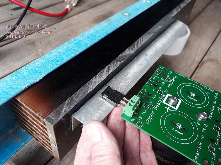
Like this, but with much thicker angle. I like the layout of them better that way.
I broke a tap inside a heatsink once, jeezus you should have heard me go nuts, it was the last one on the big heatsink of a Madinverter, so 12th one. I had to cut a bit off the bottom and start all over on another line of 12 tapped holes.
Screwing the fets to that angle could probably done with pan head self tappers with a spring washer too. That would be even easier than bolting to the angle.Cheers Caveman Mark Off grid eastern Melb
Warpspeed Guru Joined: 09/08/2007 Location: AustraliaPosts: 4406
Posted: 05:21am 03 Aug 2019
Copy link to clipboard
Print this post
That should work.
What I would do, is tap the holes, then use high tensile unbrako alan headed screws. Thread them in up from underneath so that the threaded part sticks up vertical. Those will never need to be removed. What you do then, is drop the mica insulator and mosfet onto the projecting thread, then just fit a nut on top.
The high tensile thread will never break, stretch or be damaged, and its much easier to work on just from the top as you may not be able to get your fingers underneath. Small threaded holes into aluminium are a curse, and will strip far too easily in the smaller sizes.
If you want to make absolutely sure, a dab of epoxy under the head will guarantee it will stay secure.
Cheers, ĀTony.
Solar Mike Guru Joined: 08/02/2015 Location: New ZealandPosts: 1129
Posted: 07:38am 03 Aug 2019
Copy link to clipboard
Print this post
I find its easier to tap 4mm holes in the alloy and ream the 3.6mm mounting hole in the mosfet out to fit with a 4.1mm drill.
Cheers Mike
Warpspeed Guru Joined: 09/08/2007 Location: AustraliaPosts: 4406
Posted: 09:53pm 03 Aug 2019
Copy link to clipboard
Print this post
Klaus has pointed out that 5BA screws are a good fit. Just a tad smaller than 4mm screws.Cheers, ĀTony.
renewableMark Guru Joined: 09/12/2017 Location: AustraliaPosts: 1678
Posted: 10:13pm 03 Aug 2019
Copy link to clipboard
Print this post
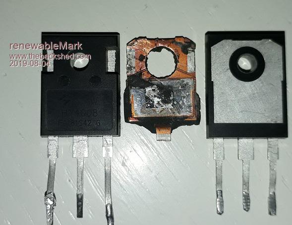
I just smashed apart a dead fet (4008).
So inside it is made of a fairly solid bit of aluminium which is connected to the drain, the front seems to have a layer of crap where the shiny bit is and the gate and drain connections sit on top of that.
So that black plastic layer at the top where the mounting hole is has no purpose?
Cheers Caveman Mark Off grid eastern Melb
mackoffgrid Guru Joined: 13/03/2017 Location: AustraliaPosts: 460
Posted: 10:18pm 03 Aug 2019
Copy link to clipboard
Print this post
you can also get M3.5 screws and taps - apparently
Cheers Andrew
Warpspeed Guru Joined: 09/08/2007 Location: AustraliaPosts: 4406
Posted: 11:06pm 03 Aug 2019
Copy link to clipboard
Print this post
It provides a very useful insulated sleeve between the drain and the screw when you wish to run the heat sink grounded.Cheers, ĀTony.
renewableMark Guru Joined: 09/12/2017 Location: AustraliaPosts: 1678
Posted: 11:13pm 03 Aug 2019
Copy link to clipboard
Print this post
That sleeve is around 1.8mm thick, so drilling like Solar Mike does should be no problem at all.
4mm tap is much more solid than 3mm.Cheers Caveman Mark Off grid eastern Melb
kentfielddude Regular Member Joined: 09/05/2019 Location: United StatesPosts: 89
Posted: 11:24pm 03 Aug 2019
Copy link to clipboard
Print this post
the only different between the hy4008-B-P-W is the package case and heat dissipation. Just cracked open a hy4008B for fun.
Hy4008b - 345W max HY4008P - 345W max Hy4008W - 397W max
Warpspeed Guru Joined: 09/08/2007 Location: AustraliaPosts: 4406
Posted: 12:18am 04 Aug 2019
Copy link to clipboard
Print this post
Should be o/k, but I suppose it depends on how much material is drilled out. That sleeve will be made thinner, and if you really heave down on the screw, may collapse under pressure. I doubt this is a problem, but its something to think about.Cheers, ĀTony.
renewableMark Guru Joined: 09/12/2017 Location: AustraliaPosts: 1678
Posted: 02:05am 04 Aug 2019
Copy link to clipboard
Print this post
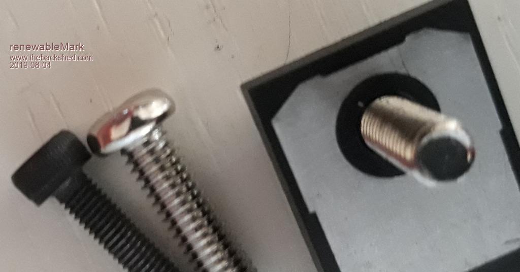
Got a 4.2mm drill bit from buggerings. Silver bolt is a 4mm, black one for comparison is 3mm.
Fet has been drilled 4.2mm and shows plenty of the plastic insulation material is left.
Cheers Caveman Mark Off grid eastern Melb
Warpspeed Guru Joined: 09/08/2007 Location: AustraliaPosts: 4406
Posted: 02:11am 04 Aug 2019
Copy link to clipboard
Print this post
4mm screw (just) fits through a mica insulator, so it all looks good.Cheers, ĀTony.
renewableMark Guru Joined: 09/12/2017 Location: AustraliaPosts: 1678
Posted: 02:18am 04 Aug 2019
Copy link to clipboard
Print this post
I won't need insulators, the big heatsink will all be positive connection and the other side will be cut into sections and held in formation by the blue fibreglass channel. So the transformer primaries will connect to the heatsinks.
Thanks Solar Mike, that's a much more solid way to mount than with 3mm bolts.
I'm having a good day, even found a heat sink I can use for the extra two boards that have been added to the plan. Edited 2019-08-04 12:49 by renewableMarkCheers Caveman Mark Off grid eastern Melb
renewableMark Guru Joined: 09/12/2017 Location: AustraliaPosts: 1678
Posted: 02:44am 05 Aug 2019
Copy link to clipboard
Print this post
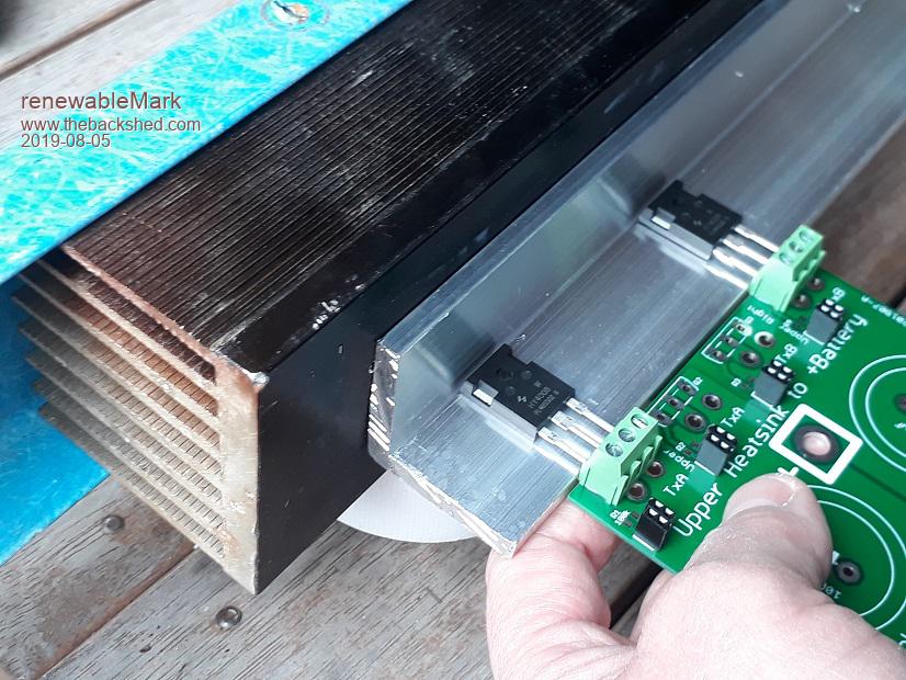
Got some 6mmx40mm. will lay it like this, that will allow good access to the bolts and have the fets close to the main heatsink.
Cheers Caveman Mark Off grid eastern Melb
Warpspeed Guru Joined: 09/08/2007 Location: AustraliaPosts: 4406
Posted: 02:55am 05 Aug 2019
Copy link to clipboard
Print this post
Very nice Mark.Cheers, ĀTony.
mackoffgrid Guru Joined: 13/03/2017 Location: AustraliaPosts: 460
Posted: 03:28am 05 Aug 2019
Copy link to clipboard
Print this post
That Aluminium angle has a cross sectional area of 444mm^2, equivalent approx to a 200mm^2 of Copper. Well and truly good enough for a buss bar without needing to take the heatsink into consideration, no need to strip the anodising off etc.
Cheers Andrew
renewableMark Guru Joined: 09/12/2017 Location: AustraliaPosts: 1678
Posted: 07:03am 05 Aug 2019
Copy link to clipboard
Print this post
Funny you mentioned that Andrew, I was thinking about doing that.
I'll still put a copper bus bar underneath as it will be a level platform for the caps to sit on. I ended up buying a whole length as it was $20/metre or a 4m length was $40 odd. So there is plenty to use.Cheers Caveman Mark Off grid eastern Melb
Solar Mike Guru Joined: 08/02/2015 Location: New ZealandPosts: 1129
Posted: 01:57am 07 Aug 2019
Copy link to clipboard
Print this post
Hey Mark, those mosfets have a thermal copper contact surface area of approx 180mm^2, so a piece of alloy bar 6mm thick has to be 30mm long to have the same area pressing against your big finned HS. Allowing for thermal losses in the 2 junctions between the mosfet and the rt angle/HS you will need prob 40mm length of the Rt angle per mosfet. So provided your mosfets are >80mm apart its a good solution.
Cheers Mike
Warpspeed Guru Joined: 09/08/2007 Location: AustraliaPosts: 4406
Posted: 02:19am 07 Aug 2019
Copy link to clipboard
Print this post
That is true if you wish to push the whole thing to the absolute thermal max.
One solution is to bolt the mosfets down onto a copper bar (which Mark already has). Then bolt the copper bar on top of the aluminium angle. That will spread the heat a lot better into the aluminium.
I had this problem when I bolted mosfets down onto a large 3mm sheet of aluminium. The thermal gradient directly under the mosfet was rather higher than I would have liked. A slab of copper made a very worthwhile improvement.
Cheers, ĀTony.
Solar Mike Guru Joined: 08/02/2015 Location: New ZealandPosts: 1129