
|
|
Forum Index : Electronics : Little China inverter board, Hary�s build
| Page 1 of 3 |
|||||
| Author | Message | ||||
| hary Regular Member Joined: 15/04/2019 Location: FrancePosts: 89 |
Hi all, My Little China inverter board arrived today : As you can see, it is already equipped with HY4008 MOSFET ! 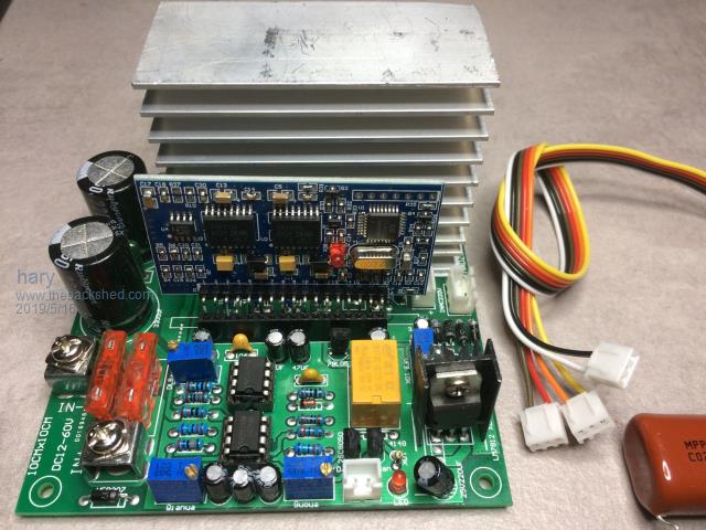 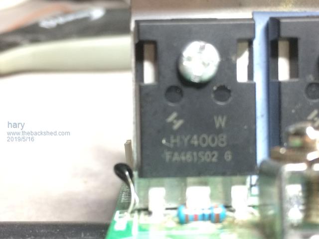 But I think there is a bridge of solder that souldn't be there : 2019-05-16_072935_IMG_2231.pdf On the EGS002 board, JP2, JP5, JP7 and JP8 are jumped, so the board is ready for : 50Hz, Soft Start ON, dead time to minimum 300ns LCD backlight off. I just wonder why they configure the board with minimum DEAD TIME. Shouldn't it be configured at the maximum or at least at a middle value to be on the safe side ? 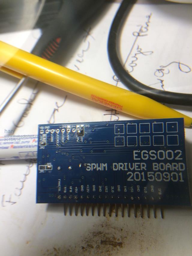 The board has R4 resistor but no C19 capacitor ! Of course, as poida advises, I'll remove R4 and U4 (LM358) I'm still waiting for my TVS diode to make the modification before plugging it in ! On the power board, there are 3 connector and 4 potentiometer. 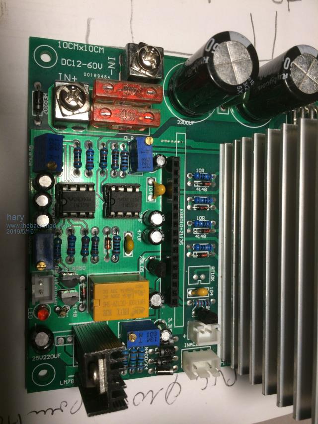 Bottom right connector is for 220V output feedback with its bottom adjustable potentiometer, What are they for ? but I have no clue about the 2 other connector and 3 other potentiometers. |
||||
| poida Guru Joined: 02/02/2017 Location: AustraliaPosts: 1389 |
That solder bridge looks very dodgy. I would clear it away and look at the underlying mask. with regards to dead time setting on these sorts of boards: I have tried all 4 DT settings. The minimum time setting makes for the lowest idle power loss. Idle power loss increased with dead time All 4 DT settings produce the same shoot through problems. Different DT settings do not alter the degree or any other characteristic of the shoot through. My view as to why the idle power increases with dead time is that the longer both low and high side switches are open, the more time one or the other MOSFET's body diode is conducting. The body diode has a voltage drop of about 0.8V at 100 Amps. This is a lot of power consumed by the diode (80W) But when the MOSFET is switched on, Rds = 2.9 mOhom at 100Amps so the power consumed becomes 100 x 100 x 2.9 x 10-3 = 29W At a lower current, say 10A, the comparison becomes 8W and 0.29W These boards have potentiometers to allow the setting of low voltage cutoff, low speed over current shutdown (very problematic) high speed over current shutdown (same) and the AC output setting. The connectors provide you to attach a remote on/off switch, a 2 colour LED to show standby/Running indication, a 12V drive for a cooling fan and the 240V AC voltage feedback. wronger than a phone book full of wrong phone numbers |
||||
| BenandAmber Guru Joined: 16/02/2019 Location: United StatesPosts: 961 |
Harry you're in the hands of one of the greats listen to him and you'll be very happy with your little inverter One suggestion when you get this one up and running and you will don't just go out and by the biggest one you can find for your next one Oh yes there will be another one the stuff is very addictive Ask around a little bit some of the greats on here and see what they think about how many mosfet for how many watts I could be wrong but I think 24 mosfets might be Overkill and mosfets been paralleled might be more of a problem than help But absolutely do not take my word for it ask around and see what some of the experts on here think before you buy your next one Poida giant ferrite chokes on my big choke post be warned i am good parrot but Dumber than a box of rocks |
||||
| BenandAmber Guru Joined: 16/02/2019 Location: United StatesPosts: 961 |
Do you have your Transformer already if so can you post pictures be warned i am good parrot but Dumber than a box of rocks |
||||
| hary Regular Member Joined: 15/04/2019 Location: FrancePosts: 89 |
The solder bridges pin 1 and 2 off one of the MOSFET and underlying mask tells it has something to do with the MOSFET gate pull down resistor that is short circuited to drain. So, I will clear that up. I see, I never though DT was important that way too ! I just got up and already learned something ! So, in fact, DT has to be really fine adjusted if you want to avoid inefficiency and exceeding heat and maybe power MOSFET failure ! Would be DT to be ideally modify during uses of the inverter ? I mean, do ideal DT change depending maybe on the actual load or something else ? Or will it stay always the same for a specific inverter ? 1 => OK 2 & 3 => No more problem as you advised to suppress EGS002's C19, R4 and U4 (LM258) 4 => OK One is 3 pin, but only 2 available, and marked "INAC220V" that must bee the 230V feedback. one is 2 pin and marked "FS12V" might go for Fan Start ? And a third one with only 2 pin with no understanding marking ! So only 3 connector, not 4 as you suggest. For a 2 colour LED, I think a 3 pin connector would be needed ! Thanks a lot for all these details ! |
||||
| hary Regular Member Joined: 15/04/2019 Location: FrancePosts: 89 |
Here it is : 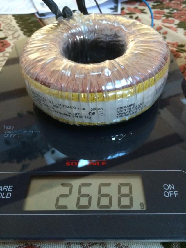 I'm expecting 200VA continuous, 1000VA peak. It's meant for the fridge ! |
||||
| hary Regular Member Joined: 15/04/2019 Location: FrancePosts: 89 |
I'm thinking right now that I've seen some people adding what they call a "choke" in series with the low voltage circuit of the transformer. Should I get one myself ? I don't really understand what it's meant for ? |
||||
| poida Guru Joined: 02/02/2017 Location: AustraliaPosts: 1389 |
A choke is an inductor, used to reduce to a small amount the high frequency energy flowing through the primary winding. These types of inverters, including most of the home made ones here, the Chinese inverter boards and the Powerjack LF types all use pulse width modulation to produce the 50 or 60Hz AC on the primary winding. Most times, the frequency of the pulses is about 20kHz (19 - 23kHz depending on the inverter) This means the DC supply is being switched into & switched out of the primary winding about 20,000 times a second, causing huge amounts of high frequency energy to be produced. This HF stuff is a problem. The solution is the choke. It can be sized such that it does not conduct much HF energy at all, but lets through the 50 or 60Hz with very little power loss. This is a good one, made by Wiseguy. He used a different core type. 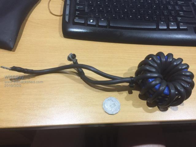 I make mine using a $20 ferrite core and a bit of wire, enough to put about 8 turns around the inner core. I used something like this We need a choke that is about 50uH and can maintain that 50uH up well past the inverter's DC current draw when loaded, at least 1.5X You put the choke in series with one of the primary winding terminals. wronger than a phone book full of wrong phone numbers |
||||
| BenandAmber Guru Joined: 16/02/2019 Location: United StatesPosts: 961 |
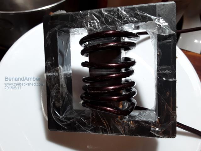 This one works very well 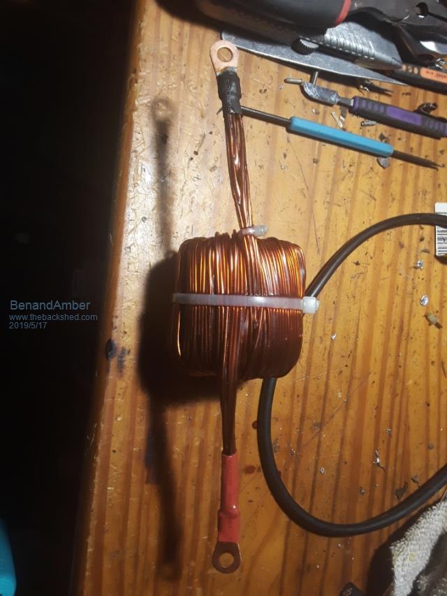 This one is like poidas pic But has 4 cores it instead of two It works well but probably too big for yours 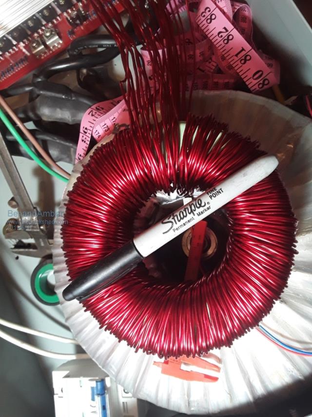 This one is ferrite material also but is 1 big core instead of 4 Was hoping somebody would comment on it I don't want to make a big mistake literally At this point I would recommend the top one I know it works very good it has a slight hum but it isn't bad at all when you have the top on the inverter be warned i am good parrot but Dumber than a box of rocks |
||||
| hary Regular Member Joined: 15/04/2019 Location: FrancePosts: 89 |
For me, and I don't know anything about inductor, the choke is nothing more than the same "topology as the primary of the transformer we use in the inverter. So, why the primary of the transformer doesn't act as the choke ? Hope you understand my question. |
||||
| BenandAmber Guru Joined: 16/02/2019 Location: United StatesPosts: 961 |
Poida the great warpspeed renewablemark WiseGuy tinyt and many others could answer this question a lot better than me With that said the choke lowers your idle current Square Transformers have leakage Toroids don't have very much leakage at all Without this leakage these boards blow up very easily That top picture is a e80 ferrite Which is probably a little bit big for your bored I think poida the great recommends a e70 ferrite 87 with a small gap And other people have recommended little sendust toroidal core be warned i am good parrot but Dumber than a box of rocks |
||||
| hary Regular Member Joined: 15/04/2019 Location: FrancePosts: 89 |
BenandAmber, This puts me in the darkness. We use toroid transformer to avoid leakage and now you say we need to add leakage with the choke ? On the other side, I can understand we want to smooth the high frequency issued from the board's MOSFET. The point I don't understand is : Why the toroid trandformer's primary doesn't smooth the high frequency itself as it is also a winding on a magnetic core ? And the picture you show just before look like toroid also ??? |
||||
| poida Guru Joined: 02/02/2017 Location: AustraliaPosts: 1389 |
The main toriod transformer usually has very small leakage inductance. This results in their good efficiency when used "normally" as a step down power transformer. I've already stated the output of the inverter board consists of nothing more than zero volts (i.e. a short) and full DC supply voltage, backed up by as much capacitance as possible. Pumping this into something of relatively low inductance will result in likely too large currents in the primary circuit. Best build practice here on the forum has the primary winding consisting of the largest gauge copper wire, with the shortest length of this copper wire. A short length of thick copper wire has little inductance. I short while ago I posted on this very subject here and it's worth your time to read it, in my view. The summary from the above link is that when we evenly space the windings of both the primary and secondary around the toroid, obtaining very even spacing between each turn, we end up minimising leakage inductance. It becomes too small and so huge current peaks will be present in the primary winding, including the MOSFET's Drain to Source current path. And so the primary choke was born. We include a choke of about 50uH and built with a core that will not saturate much if at all even up to the maximum operating output levels of the inverter. The choke absorbs the DC voltage pulse, backed up by huge capacitance, converting this into a rising current in the primary circuit. This also results in a changing magnetic field strength in the choke. We build the choke to operate efficiently and so nearly all of the magnetic field energy is returned to current. The choke acts as a shock absorber, taking the killer punch out of the huge current pulses of the PWM design. I have examined the voltage across the primary winding terminals of my inverters and when I have a good enough choke installed, all I see is clean steps in the voltage. If the choke is insufficient, I see spikes on the rising edges of these step changes. The step changes of course are due to the PWM, switching in a pulse of DC supply, which the choke absorbs, converting it to the smooth and small voltage step presented to the primary winding. Have a look here when I examine the choke's effect Often, this discussion leads to the question "how best to build a choke tester" In your case, with the 1000W inverter board, the inductor Ben & Amber showed at the top of here will be easy to build and work fine. I use 6mm2 PVC insulated house Earth wire in mine. It's more flexible to work with. Sometimes it's helpful to think of the necessary inductance as being 1/2 of a high power, low loss LC low pass filter. The filter's job is to remove the 23kHz PWM, and it's higher overtones completely, letting 50 or 60Hz through with minimal loss. The capacitor is positioned across the AC output winding. The inductor is placed.. When you put it on the secondary, there appears a capacitance across the primary, multiplied by the turns ratio. wronger than a phone book full of wrong phone numbers |
||||
| Clockmanfr Guru Joined: 23/10/2015 Location: FrancePosts: 427 |
My Personal observations on my OzInverter builds. This below is from the New second edition workshop manual of the 6kW OzInverter build process. The new book is a complete and utter new re-write, with absolutely everything about everything, 92 pages and 242 colour photographs and block diagrams, its at the printers at this very moment. Toroid ferrite Ecore choke. For further information see the technical chapter. A = 65mm (2.56") (Length) B = 45mm (1.75") C = 32.5mm (1.28") (Height) D = 22mm (0.87") E = 20mm (0.79") F = 27mm (1.06") (Width) �The ecore will drop your idle current and at the same time take an enormous amount of heat out of the transformer due to the new efficiency.... other wise it will absord hundreds or watts for nothing but heat you don't want. ���..oztules� The ferrite Ecore is very important as it reduces inverter idle current use, ie, the inverter is not using excess power while awaiting use when running, like night time when the household is asleep. With this 6kW OzInverter the running, ilde, power use is down to 30 to 40 watts. The ferrite core is commercially available as �E6527 Ferroxcube E65 E EE Ferrite Cores� , I have found this size to be the most efficient and quite. I have experimented with bigger cores with 70mm2, but then the flexible cable needs to be wound really tight or the Ecore Choke sounds like a Banshee on speed. The cores comes in two half�s, but those internal edges are very sharp so I use a fine needle file to gently round the corners. I have found this particular size hits a sweet spot. You could widen the core gap but then at high power other problems arise. Everything is possible, just give me time. 3 HughP's 3.7m Wind T's (14 years). 5kW PV on 3 Trackers, (10 yrs). 21kW PV AC coupled SH GTI's. OzInverter created Grid. 1300ah 48v. |
||||
| hary Regular Member Joined: 15/04/2019 Location: FrancePosts: 89 |
Clockmanfr, you say :"E6527 Ferroxcube E65 E EE Ferrite Cores" But is this the correct core for all kind of inverter ? The 6kW and the one I'm intending to make, so 200W continuous, 1000W surge ? Plus haw do we source core like that ? what are the data we're looking for ? From what I understood, the core modify the relative magnetic permeability compared to an air core inductance. So we should source a core with a specific permeability, I guess... |
||||
| BenandAmber Guru Joined: 16/02/2019 Location: United StatesPosts: 961 |
When you're new here sometimes it might be hard to know who to trust These greats on here their word is as good as gold They are very careful of what they say and will not lead you wrong In my post poida the great literally showed me the exact one to get And every step from beginning to end that information is still there on my post That little inverter from that post absolutely runs perfect and I beat the crap out of it everyday be warned i am good parrot but Dumber than a box of rocks |
||||
| hary Regular Member Joined: 15/04/2019 Location: FrancePosts: 89 |
Hi benandAmber. from this post Poida talks about 5000W inverter, then he says he put 100A on 6mm2 wire which is very high current /mm2 to me. I'm very humble, I'm not saying he is wrong, I'm only wondering from my own background ! Or maybe, the 5000W he's talking about is in surge condition ? And As I'm on 24V, I'd probably need bigger wire, so I don't know if I could fit the 6 turn of bigger wire on the core Poida gave the reference. Plus, again, being on 24V, it will double the current and so the same core is going to saturate much faster. This is what I understood from my "Sunday reading", so I'm not sure I need the same core as you if you're running on 48V ? So I was trying to understand this magnetic stuff. But it seems to be a big stuff, indeed ! I'll be missing this choke for the build ! |
||||
| BenandAmber Guru Joined: 16/02/2019 Location: United StatesPosts: 961 |
That sounds really good Harry I videotaped my first startup if you don't care can you videotape yours I'm thinking about putting everybody's first start up into one video and uploading it on YouTube be warned i am good parrot but Dumber than a box of rocks |
||||
| Clockmanfr Guru Joined: 23/10/2015 Location: FrancePosts: 427 |
Hi Hary. The ecore is available from this guy in Sofia, Bulgaria , he will send to most countries ........ https://www.ebay.co.uk/itm/E6527-Ferroxcube-E65-E-EE-Ferrite-Cores-bobbin-Power-transformer-AL-8600- set/370597734866?epid=1574393580&hash=item564958a9d2:g:9jMAAOSwa1hb6rmx We have found this particular size of Ecore to be about correct for the 22kg core of the toroid with the 6kW OzInverter on 48v. On a smaller 2000w it may be overkill and might be excessive. When winding the Ecore you need a minimum of 3 complete winds around the centre lump of ferrite. But as I said the windings need to be tight. The primary on a 6Kw Ozinverter is normally 15 turns of 50mm/2, so we also wind the Ecore with the flexible marine/welder type 50mm/2 cable, and its a snug fit. 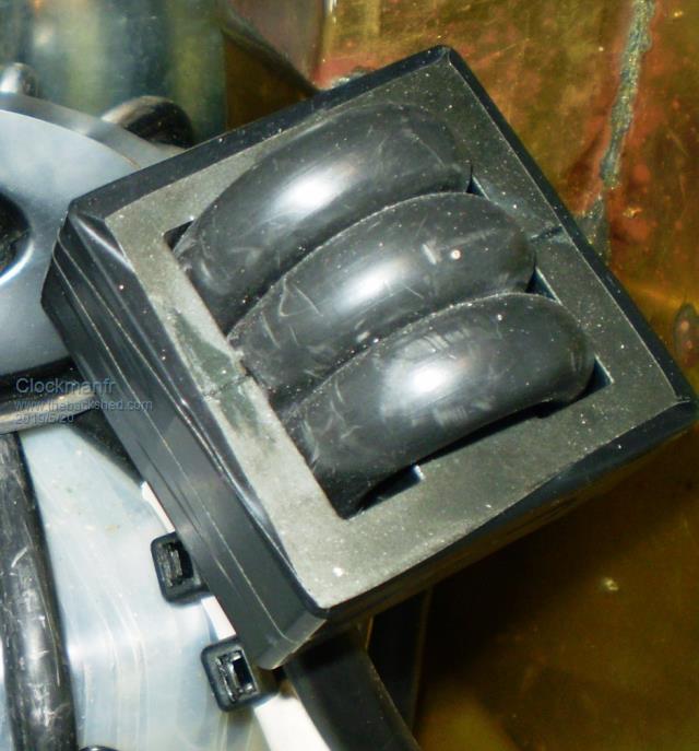 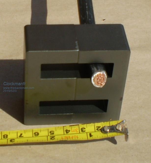 Everything is possible, just give me time. 3 HughP's 3.7m Wind T's (14 years). 5kW PV on 3 Trackers, (10 yrs). 21kW PV AC coupled SH GTI's. OzInverter created Grid. 1300ah 48v. |
||||
| Clockmanfr Guru Joined: 23/10/2015 Location: FrancePosts: 427 |
Here try this udube vid, https://www.youtube.com/watch?v=C3If9sbpdcA My teenager boy filmed this in summer 2016 showing a working OzInverter with the modified PowerJack boards, and then the 8kW BigOzInverter being assembled. However, the 8kW toroid on its own ended up at nearly 50kg and became difficult to move around. And to be honest the 6Kw OzInverter can handle huge surges and is more than adequate for all normal domestic households. So I no longer recommend the 8kW version its just not cost effective. Here is a pick inside a recent 6kW OzInverter that is under test...... 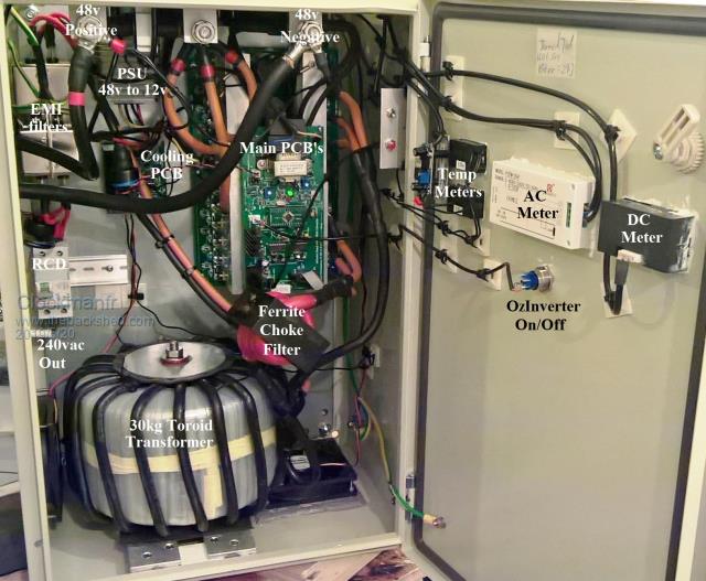 Here are the types of OzInverter.... 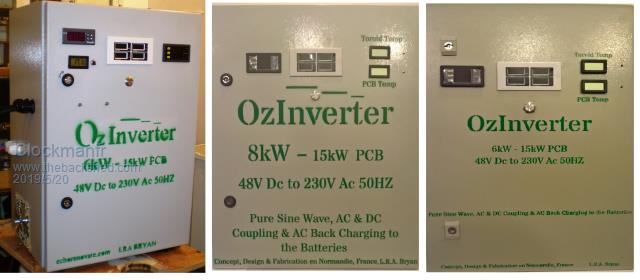 Everything is possible, just give me time. 3 HughP's 3.7m Wind T's (14 years). 5kW PV on 3 Trackers, (10 yrs). 21kW PV AC coupled SH GTI's. OzInverter created Grid. 1300ah 48v. |
||||
| Page 1 of 3 |
|||||
