
|
|
Forum Index : Microcontroller and PC projects : ILI9488 drivers: MM2 and MM+
| Author | Message | ||||
| JohnS Guru Joined: 18/11/2011 Location: United KingdomPosts: 4038 |
If you mean https://geoffg.net/Downloads/Micromite/Micromite_Firmware.zip I just tried it (bypassing browser cache) and also get errors. Here it is when it was OK. Micromite_Firmware-V5.05.05.zip John Edited 2022-01-06 18:02 by JohnS |
||||
| matherp Guru Joined: 11/12/2012 Location: United KingdomPosts: 10273 |
Haven't got one and haven't seen the article so can't help on specifics - sorry. V5.05.04 not the issue the driver was written before 5.05.04 and I've just tested on 5.05.05 OPTION LCDPANEL USER 0, 0 is correct MM.HRes/VRes will give the correct answer Possible signal error on the backpack? Easy to test if you have a scope otherwise remove the driver completely, waggle the pins using SETPIN DOUT/PIN(x)=n and check continuity to the display |
||||
| David_Plumley Newbie Joined: 03/01/2022 Location: New CaledoniaPosts: 8 |
Thank you John for the link. I'll download it tomorrow. Peter, I've got a basic scope. I'll do some checking tomorrow. What is strange is that the examples using the SC driver work OK. I'll get back tomorrow. David. |
||||
| Turbo46 Guru Joined: 24/12/2017 Location: AustraliaPosts: 1641 |
You still don't say which backpack you are using but I think it's the one from SC November 2016. The pins you are using are from that article and I think they are correct. I seem to recall that someone had an issue with a display that wouldn't work until they moved the display away from the backpack board using jumper leads. I'm not sure it was the same display but I think the backpack was different. Maybe you have the same problem. I'll see if I can find the post tomorrow. Bill Edit: DOH! it's this post. Edited 2022-01-06 21:56 by Turbo46 Keep safe. Live long and prosper. |
||||
| phil99 Guru Joined: 11/02/2018 Location: AustraliaPosts: 2626 |
If you think interference is an issue it may be worth wrapping a piece of sheet metal in plastic and sliding it between the display and the MM+. May not work but easy enough to try. Cut up and flatten a tin can if you have nothing else. |
||||
| Turbo46 Guru Joined: 24/12/2017 Location: AustraliaPosts: 1641 |
Great minds... I was thinking of aluminium foil between two pieces of cardboard. Bill Keep safe. Live long and prosper. |
||||
| David_Plumley Newbie Joined: 03/01/2022 Location: New CaledoniaPosts: 8 |
Hi all! A few hours ago, I wrote a longish post to update you all on my lack of progress. I must have done something wrong, because I've re |
||||
| David_Plumley Newbie Joined: 03/01/2022 Location: New CaledoniaPosts: 8 |
(I'll start again...) A few hours ago, I wrote a longish post to update you all on my lack of progress. I must have done something wrong (like just now...), because I've realized that my post has "disappeared"... It's getting a bit late, so I'll try again tomorrow... Sorry about that. David. |
||||
| JohnS Guru Joined: 18/11/2011 Location: United KingdomPosts: 4038 |
Use a text editor - a program like kate or notepad - then paste to here when done. John |
||||
| Turbo46 Guru Joined: 24/12/2017 Location: AustraliaPosts: 1641 |
Hi David, can we please sort out bit more detail of the problem? Firstly some facts and please correct me if I am wrong. 1. You have built the MM+ backpack from SC November 2016. 2. Peter has re checked and verified that the ILI9488 driver is working. 3. The firmware version is not an issue. 4. You have removed the MISO pin. 5. The pins in your mm.startup sub are from the November 2016 article. 6. Touch appears to be working. 7. You are trying to use Peter's MM+ driver. Now some queries: Have you tried the board with the ILI9341 display that the backpack was originally designed for? If so, and it worked, then the backpack most likely OK. You say that with the ILI9488, the SC software worked. Does that mean the driver from the SC August 2109 issue. Does that also mean that you could write to the display and see the result there? If that is so, then the backpack and the ILI9488 work together and there is no need for shields or any other modification. Your question about the GUI commands suggests to me that the display did work after a fashion but the GUI commands did not work. I think that would most likely be due to the fact that the SC driver for the ILI9488 was written for the MM2 (as used in the August 2019 article) and not the MM+. Any reason for the need for a different driver is beyond my pay grade. Maybe, in that case, other graphic commands would not work either? Did you follow the procedure from the ILI9488 driver document included in the firmware download? It wasn't apparent to me from the original post. That document gives the pins to use for the 64 pin MM+ in a table, but later says that you can change them to suit your application. I think what you have done is OK, but... Did you set the display brightness as per the November 2016 article after re-starting the MM+ and before testing Peter's driver? I hope there is something there that may help and I apologise if it sounds like I'm trying to teach my grandmother how to suck eggs but you didn't supply much detail. Bill Keep safe. Live long and prosper. |
||||
| David_Plumley Newbie Joined: 03/01/2022 Location: New CaledoniaPosts: 8 |
JohnS : Good advice, of course. I did exactly that for my first posts, but then got overconfident... Bill : I'll print your post and go through it point by point. I'm also in the process of setting an ILI9488 up on a spare E100 that I happen to have. I'll hopefully get back before the end of the day. And no, I don't mind anybody pointing out the obvious to me. Good point about the brightness, for instance... Catch you all later. David. |
||||
| David_Plumley Newbie Joined: 03/01/2022 Location: New CaledoniaPosts: 8 |
Well, sorry to have put you all to so much trouble... I finished connecting the ILI9488 to my E100, using a 5V socket on one of the mikroBUS connections for the LED pin on the display. Peter's driver worked perfectly... I then plugged the display back in the MM+ BackPack, ran Peter's driver, set the display brightness as Bill suggested and... presto! I'll see if I can't put the PWM command in the startup subroutine, so that I don't get caught out again... As I mentioned (maybe in my post that disappeared), it is sometimes difficult to see the wood for the trees! Once again, thank you for all your suggestions. I'll try and be a bit less silly next time I post... Have a nice day. David. |
||||
| Turbo46 Guru Joined: 24/12/2017 Location: AustraliaPosts: 1641 |
Easy enough done.  As I was going through my list, it seemed to me that you had done everything correctly and it was the only thing I could think of that would stop you seeing a display. Glad it's sorted. Bill Keep safe. Live long and prosper. |
||||
| phil99 Guru Joined: 11/02/2018 Location: AustraliaPosts: 2626 |
You are not the first to be caught by that. Some backlights are reversed to add to the fun. Starting with 50% will get a display on all. Re the panels with crook Data Out (MISO). I managed to damage that pin on one of my ILI9341 displays by plugging it in one hole over (old eyes). Got it going with this:- 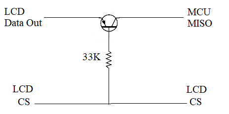 It may be worth a try on them. The transistor is a PN200 PS Not only does it restore normal operation of touch and SD card but IMAGE SAVE and BLIT READ are working also, so the pin is working as an output it just can't switch off. Edited 2022-01-08 21:22 by phil99 |
||||
| lizby Guru Joined: 17/05/2016 Location: United StatesPosts: 3367 |
Sorry but my understanding of the magic that BJT transistors perform is shaky. When you say, "it just can't switch off", what are the consequences of this? Is this a solution to the ILI9488 MISO problem--gating the MISO pin with CS? In other words, would this prevent the over-talkative MISO pin on the ILI9488 from interfering with an SD module? PicoMite, Armmite F4, SensorKits, MMBasic Hardware, Games, etc. on fruitoftheshed |
||||
| phil99 Guru Joined: 11/02/2018 Location: AustraliaPosts: 2626 |
"Is this a solution to the ILI9488 MISO problem--gating the MISO pin with CS? " I am suggesting it could be. I don't have one to test. The ILI9341 that I damaged was displaying the same issues as the ILI9488 so it is well worth someone trying it. The transistor imitates cutting the pin except when LCD-CS is low, so touch and SD work normally. If the problem with the ILI9488 is that the pin is simply short circuit rather than permanently active, as is the case on mine then it won't fix BLIT or SAVE IMAGE. |
||||
| Turbo46 Guru Joined: 24/12/2017 Location: AustraliaPosts: 1641 |
phil99"s solution is another that could well work. The only issue is that it only enables the DATA OUT pin to pull the line high when CS is low, when DATA OUT is low it is not actively pulling the line low. A pull down resistor (to 0v) on the transistor collector would help. Strange that Peter doesn't seem to want to comment on the use of a series resistor when it was he that found it to work? Bill Keep safe. Live long and prosper. |
||||
| phil99 Guru Joined: 11/02/2018 Location: AustraliaPosts: 2626 |
" it only enables the DATA OUT pin to pull the line high when CS is low, when DATA OUT is low it is not actively pulling the line low. A pull down resistor (to 0v) on the transistor collector would help." I think mine works without the pull down resistor because the emitter can act as a collector and vice versa, with much reduced gain. The reverse beta is typically around 1/10 of forward. This only works at low voltages as the B-E reverse breakdown voltage is only 6 to 8V. If you do use a pulldown resistor perhaps it could go to LCD-CS instead of 0V. Tried it on mine and it works as before. |
||||
| matherp Guru Joined: 11/12/2012 Location: United KingdomPosts: 10273 |
Unable to test so not willing to comment |
||||
| matherp Guru Joined: 11/12/2012 Location: United KingdomPosts: 10273 |
UPDATE Can confirm both touch and SDcard working with a 680ohm resistor in the MISO line from the LCD. LCD then also works with BLIT, PIXEL() and transparent text. CAUTION the display I just purchased doesn't have a 3.3V regulator on the VDD input so if I was to put 5V on that pin then the SDcard would also get 5V -BAD!!! 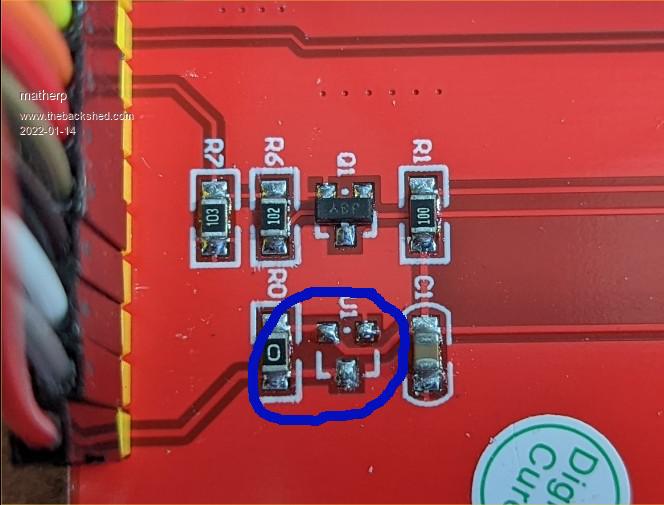 |
||||
| The Back Shed's forum code is written, and hosted, in Australia. | © JAQ Software 2025 |
