
|
|
Forum Index : Electronics : 24v Nano/Madinverter
| Page 1 of 3 |
|||||
| Author | Message | ||||
renewableMark Guru Joined: 09/12/2017 Location: AustraliaPosts: 1678 |
Hey guys, my HF inverter in the van went pop so will build a small Mad power board run by the nano control board. Highest load will be a small microwave, which is 1800w I think. Would prefer not to have a start up procedure, just want to turn it on without the need to charge caps. I have seen Poida's little bench one do that easily time and time again. That unit has small caps on it though. Maybe it will need to have only 2 fitted? Also the torroid will need to be wound differently to normal Ozinverters. So blank canvas, any suggestions on how this should get wound? 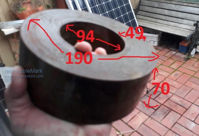 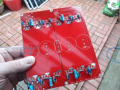 Cheers Caveman Mark Off grid eastern Melb |
||||
mackoffgrid Guru Joined: 13/03/2017 Location: AustraliaPosts: 460 |
What's the battery voltage? |
||||
| renewableMark Guru Joined: 09/12/2017 Location: AustraliaPosts: 1678 |
24v Cheers Caveman Mark Off grid eastern Melb |
||||
| BenandAmber Guru Joined: 16/02/2019 Location: United StatesPosts: 961 |
I like that board be warned i am good parrot but Dumber than a box of rocks |
||||
| mackoffgrid Guru Joined: 13/03/2017 Location: AustraliaPosts: 460 |
So, I seem to remember the Ozinverter likes a nominal 16v primary for a battery voltage of 24v. ?? I would wonder if going for a low Flux density (1T at 16v) would result in a more reliable unit. Again ?? 1T @ 16v So I make that a turns ratio of 15 Np = 21 turns of 50mm2 Ns = 315 turns of 2.5mm2 1.4T @ 16v Np = 15 turns of 50mm2 Ns = 225 turns of 2.5mm2 But I've never built a OzInverter so I'm probably wrong  Nice to see what others come up with. Cheers Andrew |
||||
| Warpspeed Guru Joined: 09/08/2007 Location: AustraliaPosts: 4406 |
Cross sectional area 49 x 70 = 34.3 cm sq Using our trusty flux calculator https://www.daycounter.com/Calculators/Max-Flux-Density-Calculator.phtml 230v .00005 Mhz (four zeros) 300 turns 34.3 cm sq Result 10,068 gauss (1.0068 Teslas in metric) 1800w = 230v x 7.8 amps At 4amps per mm sq, we need 1.96mm sq wire 1.6mm diameter wire = 2.0mm sq, so 300 turns of that for our secondary. Hole diameter 94mm circumference about 295mm In theory 184 turns on first layer and 178 on second layer. Should be possible to fit on 300 turns if you do two full laps of the core. Primary would be 18 or 19 turns of 32mm sq, giving a ratio of about 16:1 which should work down to about 20v dc or so. Cheers, ĀTony. |
||||
| Warpspeed Guru Joined: 09/08/2007 Location: AustraliaPosts: 4406 |
Yup, You beat me to the draw Andrew. Slight differences I designed for 230v you for 240v Primary turns depend on how low you plan to push your battery voltage. Andrew prefers 1.8mm wire which is going to be better, and it should also fit better with two laps around the core. Thicker primary would be better to, if it will fit. Cheers, ĀTony. |
||||
| renewableMark Guru Joined: 09/12/2017 Location: AustraliaPosts: 1678 |
Thanks guys, I do have a lot of 1.8mm that could be used. Cheers Caveman Mark Off grid eastern Melb |
||||
| mackoffgrid Guru Joined: 13/03/2017 Location: AustraliaPosts: 460 |
Thanks Tony, I was hoping you'd check my numbers Good Luck Mark Cheers Andrew |
||||
| renewableMark Guru Joined: 09/12/2017 Location: AustraliaPosts: 1678 |
Well that makes it easy with just one secondary, I'll have to mylar the crap out of it before overlapping. Cheers Caveman Mark Off grid eastern Melb |
||||
| renewableMark Guru Joined: 09/12/2017 Location: AustraliaPosts: 1678 |
Wife was talking about going on a van trip soon, so better hurry up on this project. It ended up using 1.8mm diameter, that's 2.5mm2, so good for 10amps. That will be way more than enough as the van usually runs some CFL's and a small tv, occasional micro. Thankfully it has a gas oven and cooktop and heating is with a diesel unit, so it will get a very easy life. 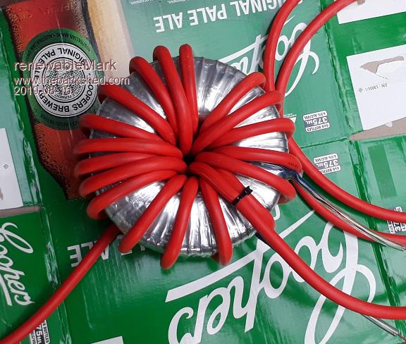 300 secondary windings and 19 primary . Edited 2019-08-10 15:19 by renewableMark Cheers Caveman Mark Off grid eastern Melb |
||||
| renewableMark Guru Joined: 09/12/2017 Location: AustraliaPosts: 1678 |
Gave up on the idea of being able to just turn it on without a procedure. It really only has two simple steps so even a drunken spaz should be able to do it. Anyway I got the heatsinks all cut, re-used the old heatsinks from my first Ozinverter. They were too small for a Madinverter. They almost got tossed in a clean up, glad they got kept now. 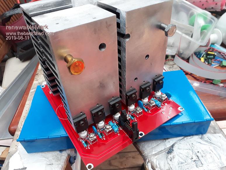 If anyone in Melb want to use my tablesaw just yell out, it has an aluminium blade on it and cut nicely. . Edited 2019-08-11 16:18 by renewableMark Cheers Caveman Mark Off grid eastern Melb |
||||
| renewableMark Guru Joined: 09/12/2017 Location: AustraliaPosts: 1678 |
Trying to work out a layout, this thing is still going to be quite a big size, way bigger than the high frequency unit it's replacing. There is a shelf under the kitchen bench where the other one was and the wiring and two batteries are. Hopefully it can squeeze in there. Considering it will normally be loaded with 100-200 watts and run 1800 watts for microwave (and it doesn't always get used on a trip anyway) I was thinking the flat version of heatsinks like this. Under 99% of loads it will cop max 200w so this should be just fine. Temp sensors and push pull fans would be fitted to the left and right of the case. No natural convection, but with such small loads it shouldn't matter hey? 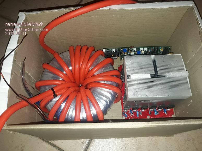 Next layout would be the more normal way to layout the heatsinks, but they will need a hole cut in the shelf to run a fan from underneath. This also increases the overall height of the unit. 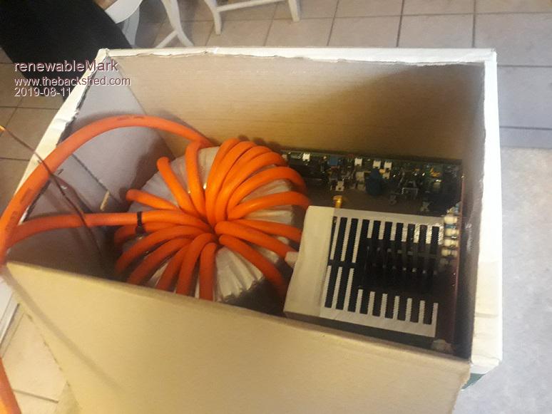 BTW I was just mocking it up in a beer box, it's not going to actually get fitted in one. This was going to get some 10,000uf 100v caps that are already on hand, but since this is 24v it could use 35v caps correct? So then it could run 47,000uf caps that would still fit in nicely and not cost a lot. . Edited 2019-08-11 21:02 by renewableMark Cheers Caveman Mark Off grid eastern Melb |
||||
| mackoffgrid Guru Joined: 13/03/2017 Location: AustraliaPosts: 460 |
Caps sound ok. I wouldn't worry about orientation to much from a cooling perspective. At an average of a couple of hundred watts, and those heatsinks, the fans will only come on when you run your uwave. Cheers Andrew |
||||
| BenandAmber Guru Joined: 16/02/2019 Location: United StatesPosts: 961 |
That looks awesome mark almost a work of art I really like that small board I'm going to try to build a new small board design this winter hopefully if I can get this Nano programming down be warned i am good parrot but Dumber than a box of rocks |
||||
| renewableMark Guru Joined: 09/12/2017 Location: AustraliaPosts: 1678 |
Thanks Ben, it's a really good size actually, and at 4kw constant it's probably more than enough for a lot of homes. This one is 24v though and will only be rated to 2kw constant. Now it's a work of art. 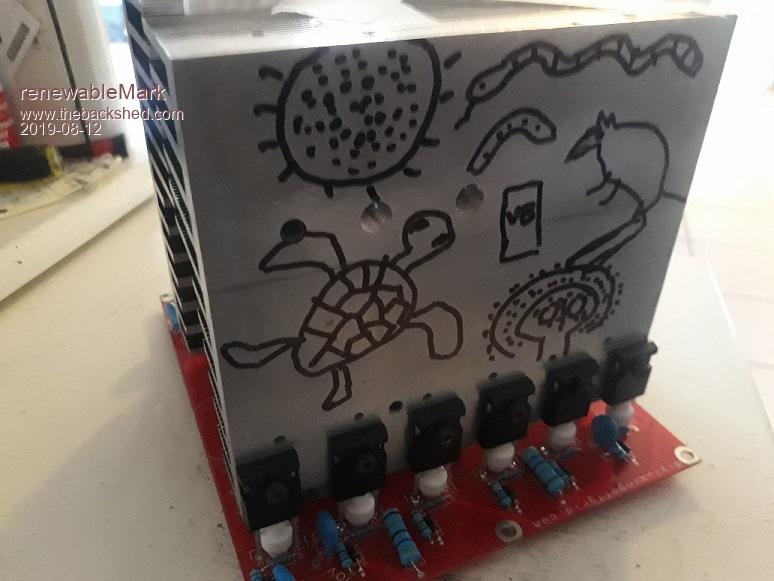 BTW with the arduino have a look at this GUIDE THIS ONE is good too. . Edited 2019-08-12 08:31 by renewableMark Cheers Caveman Mark Off grid eastern Melb |
||||
| BenandAmber Guru Joined: 16/02/2019 Location: United StatesPosts: 961 |
It truly is you even doodle good what can you not do How wide is that board I have a unique heatsink I would like to use Edited 2019-08-12 08:31 by BenandAmber be warned i am good parrot but Dumber than a box of rocks |
||||
| renewableMark Guru Joined: 09/12/2017 Location: AustraliaPosts: 1678 |
6 inches by 7 inches Or 150mm by 177mm The actual heatsinks are 140mm wide for the single big one and the 2 smaller ones are 65mm wide. You can of course hang them over the sides more if you want. This one got done as compact as it could. BTW Ben I was just clowning around with the "art" pictures on the inverter. I wonder if the wanjina or the sacred VB can will protect it from blowing up. . Edited 2019-08-12 17:33 by renewableMark Cheers Caveman Mark Off grid eastern Melb |
||||
| renewableMark Guru Joined: 09/12/2017 Location: AustraliaPosts: 1678 |
Hey Tony, just thinking about tuning this torroid for 75hz, I'll need your help again mate, if you're happy to do it again for me. Just as a starting point to get something running would 2uf be a sensible amount? The first big double stack one needed 6uf and the second one the same size needed 12uf. This core is just a single one and a bit smaller as well, probably 10% smaller than the normal 3kw cores. I can't remember which way it's safer to keep it away from 50hz more or less uf. Cheers Caveman Mark Off grid eastern Melb |
||||
| Warpspeed Guru Joined: 09/08/2007 Location: AustraliaPosts: 4406 |
If you are going to run it without a choke, best not to add any additional capacitance across the toroid. The waveform is going to turn horrible with that microwave running, no matter what else you do. Should work fine with just normal light loads. Cheers, ĀTony. |
||||
| Page 1 of 3 |
|||||
| The Back Shed's forum code is written, and hosted, in Australia. | © JAQ Software 2025 |
