
|
|
Forum Index : Microcontroller and PC projects : UBW32-based MaxiMite - some problems
| Page 1 of 2 |
|||||
| Author | Message | ||||
| Decoy Senior Member Joined: 02/08/2019 Location: DenmarkPosts: 109 |
Hi guys I am new here (!). Since watching the 8-Bit Guy video regarding the MaxiMite, I have been very interested in this 'concept' - in need of a better word :) I have just received my UBW32 in the mail, and flashed it with MMBasic (ColourMM_MMBasic_V4.5C.hex), following the instructions to the best of my abilities. All this went well, according to the bootloader. However, when I then reset the microcontroller, the PC (Windows 10) does not see the unit in any way. Nothing is popping up in device manager or anything. As such, I cannot connect with a terminal, like Tera Term. Any advice what I should do? Thanks, Nicholas |
||||
TassyJim Guru Joined: 07/08/2011 Location: AustraliaPosts: 6538 |
Welcome to the forum. Under Windows 10, it should appear as a "USB serial device" and use a Microsoft driver. Did you use a PicKit to load the firmware? It has been a while, but I think you need to load a version of MMBasic that includes the bootloader and then use it to load the latest version with Geoff's program. Jim VK7JH MMedit |
||||
bigmik Guru Joined: 20/06/2011 Location: AustraliaPosts: 2981 |
Hi Decoy, Yes it has been a long time since I reflashed a UBW32 also. I did design a PCB for the UBW32 (no longer available) but the manual I wrote may be of help to you. UBW-CMM.pdf Kind Regards, Mick Mick's uMite Stuff can be found >>> HERE (Kindly hosted by Dontronics) <<< |
||||
| Geoffg Guru Joined: 06/06/2011 Location: AustraliaPosts: 3362 |
Probably you have not loaded the correct USB serial port driver. MMBasic on the UBW32 uses a different driver to the firmware originally supplied with the UBW32. Download and install the "Silicon Chip USB Serial Driver" from the downloads section of http://geoffg.net/maximite.html#Downloads Geoff Geoff Graham - http://geoffg.net |
||||
| Decoy Senior Member Joined: 02/08/2019 Location: DenmarkPosts: 109 |
Hi guys, thanks for your answers! In relation to Geoff's post on installing the Silicon Chip USB Serial Driver, I did try that - but as the unit does not show up in device manager, I cannot point to the Silicon Chip USB driver. Maybe my Windows 10 skills is not up to par. Is there a way to install that driver without first getting the unit detected? If this turns out not to work (connecting to Windows) it should still work with on the board, I mean when I get to hook up VGA and PS/2 keyboard - as a standalone unit? Thanks again! |
||||
| Geoffg Guru Joined: 06/06/2011 Location: AustraliaPosts: 3362 |
It should show up at least as an "Undefined device". If it does not do that you then have a serious issue. You also should see the VGA output with no USB and keyboard. If none of these works you might have loaded the wrong firmware or otherwise corrupted the program running in the board. Another possibility is a bad power supply. Geoff Graham - http://geoffg.net |
||||
Grogster Admin Group Joined: 31/12/2012 Location: New ZealandPosts: 9975 |
Hello. Welcome to the forums.  The CMM(Colour Maximite) versions should all give you a nice colour startup splash-screen when you power it on with a VGA monitor connected. A barebones test would be along the lines that Geoff just suggested. 1) Connect VGA monitor and power. 2) Switch on. You should immediately see the CMM start-up screen - even with no USB or keyboard connected. If you are not even getting that, then this means either the firmware was not successfully flashed into the PIC32 chip, or that it was, BUT it is not running. In that event(no startup screen), the USB part of the PIC32 chip will also not be active, and so Windoze will not recognise a USB device being connected - neither will Linux or MAC if the firmware is not running, as that has to be running before the USB part of the PIC32 chip is started - so you get nothing.  Can you please confirm that you are at least getting the start-up message on a VGA monitor when you power up the UBW32? Smoke makes things work. When the smoke gets out, it stops! |
||||
| bigmik Guru Joined: 20/06/2011 Location: AustraliaPosts: 2981 |
Decoy, I also found several UBW32 that had problems with the VCap (10uf) I piggybacked a second 10uf over the top of the original.. One of the reasons I have stayed with the low esr 47uf tantalum capacitor for VCap Regards, Mick Mick's uMite Stuff can be found >>> HERE (Kindly hosted by Dontronics) <<< |
||||
| Decoy Senior Member Joined: 02/08/2019 Location: DenmarkPosts: 109 |
In order to do this, I need to use 1N4148s connected to ground from each colour line. I don't have these to hand, can I substitute with other diodes? Thanks! Nicholas |
||||
| Decoy Senior Member Joined: 02/08/2019 Location: DenmarkPosts: 109 |
While I ascertain if the diodes need to be 1N4148s...and wait for them to arrive in the mail, I will show what I did to flash the UBW32: 1. I connect the UBW32 with USB to a Win 10 PC 2. I run the BootLoader 3. I flash the UBW32 with ColourMM_MMBasic_v4.5C.hex 4. Bootloader confirms everything is OK 5. I reboot the UBW32, and then nothing is seen by Win 10 (on three diff. PCs) 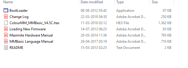 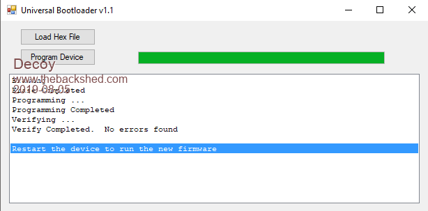 Thanks, Nicholas |
||||
| twofingers Guru Joined: 02/06/2014 Location: GermanyPosts: 1761 |
Hi Nicholas (Decoy), why are you assuming you have to use 1N4148 diodes? AFAIK should almost any "regular" silicon diode do the job (eg 1N4001). Regards Michael causality ≠ correlation ≠ coincidence |
||||
| Decoy Senior Member Joined: 02/08/2019 Location: DenmarkPosts: 109 |
Hey Michael From the manual - see picture below. I assumed that some sort of fast switching was needed? 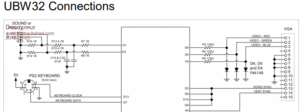 |
||||
| twofingers Guru Joined: 02/06/2014 Location: GermanyPosts: 1761 |
Hi Nicholas (Decoy), IMHO is the 1N4148 diode a universal standard diode, wich can be replaced (and replace) by almost any "regular" silicon diode. Please google "1n4148 diode wiki" and "1n4148 diode replacement". Or just try with some diode of your spare box! Michael causality ≠ correlation ≠ coincidence |
||||
| Decoy Senior Member Joined: 02/08/2019 Location: DenmarkPosts: 109 |
Okay, the UBW32 is working. I got a picture using 1N4001s and 130 ohm resistors (didn't have any 120 ohm). The picture is grainy with washed out colors, but that is probably due to the breadboard and dupont lead upon dupont lead. Or the wrong resistors? Thanks for all the help thus far! 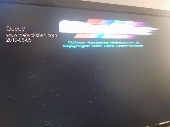 |
||||
| twofingers Guru Joined: 02/06/2014 Location: GermanyPosts: 1761 |
Hello Nicholas (Decoy), congratulations! We are one step ahead. [= D>] Ignore that. Later, if available, you can replace the 1N4001 with the 1N4148. The keyboard works too? Michael causality ≠ correlation ≠ coincidence |
||||
| Turbo46 Guru Joined: 24/12/2017 Location: AustraliaPosts: 1693 |
Hello Decoy, The 1N4148 is a high speed switching diode while the 1N4001 is a rectifier diode. This is probably the cause of the bad video. I suggest that you change them when you can. I don't think the resistor value is important. Good luck and well done so far. Bill Keep safe. Live long and prosper. |
||||
| Grogster Admin Group Joined: 31/12/2012 Location: New ZealandPosts: 9975 |
Yes, I agree with all the other posts, and well done. I also agree with Turbo46 above. 4148 diodes are 'Small signal' diodes, and are a fast diode, whereas 4001-4007 are slow-speed rectifier diodes designed for DC power passing/blocking or AC-to-DC rectification, where the frequency is normally less then 100Hz. The three SPI channels used to generate the three VGA colour signals run very fast, and the poor old rectifier diodes probably just cannot keep up with the pulse-rate from those pins. To put it in simple terms. I too would be very interested to see what happens if you switch the 4001's for the correct 4148's. Smoke makes things work. When the smoke gets out, it stops! |
||||
| Decoy Senior Member Joined: 02/08/2019 Location: DenmarkPosts: 109 |
Well, I ordered some 1N4148s locally, for your convinience - this way you didn't have to wait very long. I just replaced the 1N4001s with the 1N4148s, and the results were great! See video below. However, I still suffer from sparkles...also present in the video. Could this be due to the manual stating that pin 5, 6, 7, 8 on the VGA connector should be tied to ground? I have not done that, I just snipped the end of a VGA cable. https://www.youtube.com/watch?v=EZev2BADxrk&feature=youtu.be Thanks! Edited 2019-08-07 01:14 by Decoy |
||||
| Turbo46 Guru Joined: 24/12/2017 Location: AustraliaPosts: 1693 |
Hi Decoy, If you have a look Here you will see that pin 5 is ground for the horizontal sync and pins 6,7 and 8 are return connections for red, green and blue. These are probably in twisted pairs with the signal wiring so connecting them to ground should reduce interference (cross coupling between signal wires) which could be causing your sparkles. Pin 10 is also the return for the vertical sync and should be connected to ground as well. It's also possible that the sparkles are caused by external noise, like from a switching power supply, but grounding those connections would be a good start. If they are still there after that - try another (linear) power supply. Bill Keep safe. Live long and prosper. |
||||
| Decoy Senior Member Joined: 02/08/2019 Location: DenmarkPosts: 109 |
I fixed the problem with sparkles in the RGB video signal. By connecting the USB cable(for powering the UBW32) to a different charger, the image became a lot better with no sparkles. When connecting the USB cable to the USB connector in the monitor, ghosting became almost non-existing. Probably due to shared ground. I have hight hopes for the image quality when the real VGA connector shows up, and I can ditch the breadboard :) Thanks! |
||||
| Page 1 of 2 |
|||||
| The Back Shed's forum code is written, and hosted, in Australia. | © JAQ Software 2026 |
