
|
|
Forum Index : Microcontroller and PC projects : DUMB DISPLAY
| Author | Message | ||||
| BrianP Senior Member Joined: 30/03/2017 Location: AustraliaPosts: 292 |
+5  |
||||
| robert.rozee Guru Joined: 31/12/2012 Location: New ZealandPosts: 2437 |
old VGA monitors will continue to fail at a steady rate, this is the nature of electronic devices, especially with the introduction of lead-free soldering processes over the last decade. while there are VGA to HDMI converters available today, these will only stay on the market while there is mass demand. now having said this, i would expect to see more low-end SOC devices turn up with HDMI integrated on the chip. the RPi is one example, and eventually the likes of microchip will come up with a pic32 that has an HDMI port onboard - the HDMI connector has 19 pins, and i'm sure there are a few redundant ones. cheers, rob :-) |
||||
| lizby Guru Joined: 17/05/2016 Location: United StatesPosts: 3358 |
Again, if it's mmbasic and hdmi that you want, what's wrong with Pi-Cromite? No new device design required. Here's pi-cromite hdmi output to a 7" monitor from a pi zero W--1024x600 pixels. (Photo doesn't do justice to the clarity of the display.) 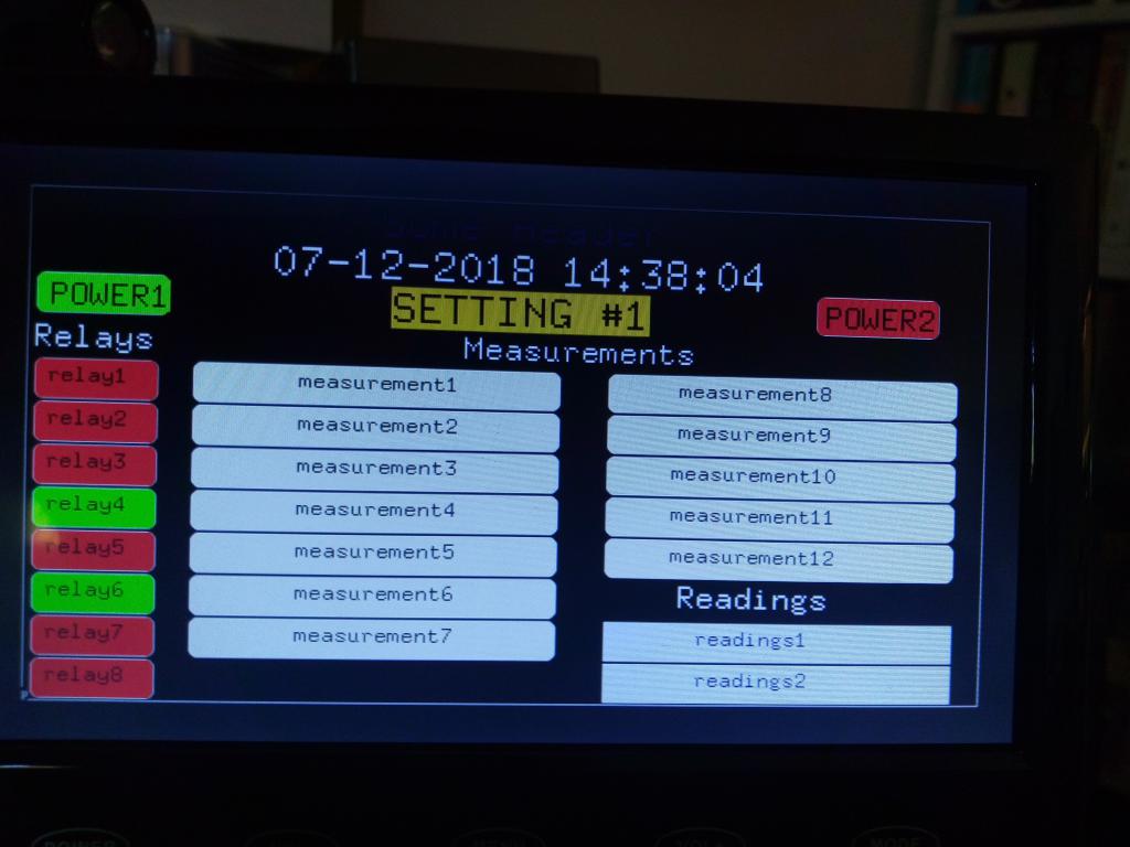 Edited 2019-09-16 22:49 by lizby PicoMite, Armmite F4, SensorKits, MMBasic Hardware, Games, etc. on fruitoftheshed |
||||
| PeterB Guru Joined: 05/02/2015 Location: AustraliaPosts: 655 |
Good afternoon lizby My original request was for composite to suit things like car/truck rear view systems as well as conventional TVs. However, HDMI converters are cheap so good idea apart from the fact that I have no experience with Pi-cromite. This has become one learning curve after another. Wonderful. Peter |
||||
| lizby Guru Joined: 17/05/2016 Location: United StatesPosts: 3358 |
That's been my experience since I took up computer programming in 1970. Glad the little grey cells still function sometimes. PicoMite, Armmite F4, SensorKits, MMBasic Hardware, Games, etc. on fruitoftheshed |
||||
| PeterB Guru Joined: 05/02/2015 Location: AustraliaPosts: 655 |
Are you talking about yours or mine when you say "still function sometimes"? The Pi-cromite seems to be missing analog in. Another possible is the MM eXtreme but I can't find out much about it yet like, how much and where from. Peter |
||||
| lizby Guru Joined: 17/05/2016 Location: United StatesPosts: 3358 |
Mine, mine. True, but ADS1115 4 Channel 16 Bit I2C ADC Module provides a fairly easy solution. Grogster has a pi backpack with LCD plus I2C (and other) connectors. And it's not hard to do i2c with just flying leads (keeping in mind that R-Pi inputs are not 5V tolerant. Edited 2019-09-17 11:09 by lizby PicoMite, Armmite F4, SensorKits, MMBasic Hardware, Games, etc. on fruitoftheshed |
||||
| PeterB Guru Joined: 05/02/2015 Location: AustraliaPosts: 655 |
So, in other words, mine are not functioning correct? I hope your chickens turn into emus and kick your chook-shed down.  I am a bit busy at the moment, SHE is in hospital and I am spending 3-4 hours a day visiting and the rest is housework, sleeping and TBS. However, something will come from this. Peter |
||||
| lizby Guru Joined: 17/05/2016 Location: United StatesPosts: 3358 |
LOL. Any claim I make concerning the functioning status of my own grey cells implies nothing about that of others. PicoMite, Armmite F4, SensorKits, MMBasic Hardware, Games, etc. on fruitoftheshed |
||||
Quazee137 Guru Joined: 07/08/2016 Location: United StatesPosts: 593 |
Im driving a 4" backup camera display with the composite output from a RPi Zero W. �Haven't loaded the MMBasic on the RPi yet playing with "learning" Python.  � There is a lot of code at Adafruit � Adafruit �1115 � code on git �Adafruit more upto date git code � Here is some MMBasic test code for the ADS1115 derived from the code at Adafruit. � 'RTC and ADS1115 modules on I2C pins 18,17, pin 16 DS18B20 temperature sensor 'A0 & A1 PH input, A2 temp from probe, A3 0 to 5 volt raw inputs Option explicit Dim float adc01,adc23,adc0,adc1,adc2,adc3,getvolts,tmp,ofs=-2.67,wait=100 Dim startime$ RTC gettime 'RTC SETREG &h07,&h92 startime$=Time$ Dim fs=2,p=0 I2C open 100,5000 Box 0, 0, MM.HRes-1, MM.VRes-1, 8, , RGB(yellow) PWM 2,1000,50 ' 'SetTick 3600000,settime,1 'update time from RTC hourly SetTick 7*wait,ADC,4 'periodical reading clr Do locate 5,1 Print startime$;" ";Time$;" " Print "Volts A01 is "; Str$(adc01,0,3),Str$((adc01+.414.12)/.05916,0,3);" pH" Print "Volts A23 is "; Str$(adc23,0,3) Print "----------------------" Print "Volts A0 is "; Str$(adc0,0,3) Print "Volts A1 is "; Str$(adc1,0,3) Print "Volts A2 is "; Str$(adc2,0,3) Print "Volts A3 is "; Str$(adc3,0,3) Print "Temp ";Str$((adc2-2.7315)*100,0,3);" C " Print "Temp ";Str$((adc2-2.7315)*100*(9/5)+32,0,3);" F " Print "Temp ";Str$((adc2-2.7315)*100*(9/5)+32+ofs,0,3);" F " Print "--------------------" tmp=TEMPR(16) Print "The temp ";Str$(tmp,0,3);" C ",Str$(tmp*1.8+32,0,3);" F " 'Print "24.8 C is ";Str$(24.8*(9/5)+32,0,3);" F " Text MM.HRes/2,30,Date$+" "+Time$,cm,1,fs,RGB(red),RGB(yellow) Text 10,40,"A01 is "+Str$(adc01,2,3),,1,fs,RGB(blue),RGB(yellow) Text 10,65,"A23 is "+Str$(adc23,2,3),,1,fs,RGB(blue),RGB(yellow) Text 10,90,"A0 is "+Str$(adc0,2,3),,1,fs,RGB(blue),RGB(yellow) Text 10,115,"A1 is "+Str$(adc1,2,3),,1,fs,RGB(blue),RGB(yellow) Text 10,140,"A2 is "+Str$(adc2,2,3),,1,fs,RGB(blue),RGB(yellow) Text 10,165,"A3 is "+Str$(adc3,2,3),,1,fs,RGB(blue),RGB(yellow) Text 10,190,"Tmp is "+Str$(tmp*1.8+32),,1,fs,RGB(blue),RGB(yellow) Loop Sub ADC ' ADC reading Local cfreg,cnv,cfhi,cflo cfreg = &h01: cnv =&h00 ' rate 128 sps no comp operations cfhi = &h83 : cflo= &h81 'reading Dif Ain0 , Ain1,FS= +/- 4.096 , 128 sps I2C write &H48,0,3,cfreg,cfhi,cflo 'adr 48 point to config reg I2C write &h48,0,1,cnv ' adr 48 point to conversion reg getadc adc01 = (getvolts+adc01)/2 ' cfhi = &hB3 : cflo= &h81 ' reading Dif Ain2 , Ain3,FS= +/- 4.096 , 128 sps I2C write &H48,0,3,cfreg,cfhi,cflo 'adr 48 point to config reg I2C write &h48,0,1,cnv ' adr 48 point to conversion reg getadc adc23 = (getvolts+adc23)/2 ' cfhi = &hC3 : cflo= &h81 ' reading single Ain0,FS= +/- 4.096 , 128 sps I2C write &H48,0,3,cfreg,cfhi,cflo 'adr 48 point to config reg I2C write &h48,0,1,cnv ' adr 48 point to conversion reg getadc adc0 = (getvolts+adc0)/2 ' cfhi = &hD3 : cflo= &h81 ' reading single Ain1,FS= +/- 4.096 , 128 sps I2C write &H48,0,3,cfreg,cfhi,cflo 'adr 48 point to config reg I2C write &h48,0,1,cnv ' adr 48 point to conversion reg getadc adc1 = (getvolts+adc1)/2 ' cfhi = &hE3 : cflo= &h81 ' reading single Ain2,FS= +/- 4.096 , 128 sps I2C write &H48,0,3,cfreg,cfhi,cflo 'adr 48 point to config reg I2C write &h48,0,1,cnv ' adr 48 point to conversion reg getadc adc2 = (getvolts+adc2)/2 ' cfhi = &hf3 : cflo= &h81 ' reading single Ain1,FS= +/- 4.096 , 128 sps I2C write &H48,0,3,cfreg,cfhi,cflo 'adr 48 point to config reg I2C write &h48,0,1,cnv ' adr 48 point to conversion reg getadc adc3 = (getvolts+adc3)/2 End Sub Sub getadc Local adcv Local integer adcrd(2) 'to receive 2 bytes Pause wait/2 I2C read &h48,0,2,adcrd() adcv= (adcrd(0)<<8) Or adcrd(1) If adcv > &H7fff Then adcv = adcv - &HFFFF getvolts = adcv *(4.096/32768.0) End Sub Sub settime RTC gettime Pause 50 End Sub Sub I2Cscan Local found, i,h$, temp found=0 Print "I2C-Scanner from Adr. 8-119":Print For i = &h08 To &h77 ' gueltige I2C-Adressen von 8-119 I2C open 100, 1000 ' i2c enable 100kHz, 1000ms timeout I2C read i, 0, 1, temp If MM.I2C = 0 Then Print "Found I2C-Address at "; i; " (&H";Hex$(i);")" found=1 EndIf I2C close ' i2c disable Next i If found = 0 Then Print "NO I2C-Address found!" End Sub Sub clr Print Chr$(27)+"[f" : Print Chr$(27)+"[2J" End Sub Sub locate x,y Print Chr$(27)+"["+Str$(X)+";"+Str$(Y)+"f"; End Sub Edited 2019-09-18 00:59 by Quazee137 |
||||
| PeterB Guru Joined: 05/02/2015 Location: AustraliaPosts: 655 |
G'Day Quazee. Your display is more or less where this started. I am still waiting for my converter so that I can try Nancye's 7 in display. How good / bad is your display? Peter |
||||
| PeterB Guru Joined: 05/02/2015 Location: AustraliaPosts: 655 |
Here I am, back again. After the usual wait my converter arrived except it was AV to VGA. After another wait the thing I ordered arrived. I connected it between my colour maximite and an AWA TV. The display is not good. o and e look about the same. I have been busy with Nancye's health problems of late and have not tried her 7 in truck display and there is probably not much point in doing so. What a bummer  Peter |
||||
| matherp Guru Joined: 11/12/2012 Location: United KingdomPosts: 10240 |
From the Pi-cromite manual |
||||
| PeterB Guru Joined: 05/02/2015 Location: AustraliaPosts: 655 |
Thanks P I am aware that an ADC could be added but that is getting away from my idea of a nice simple solution. If there is enough interest in using a dumb display then someone will design the necessary kit to interface between an E64 and a display. I don't think I am that someone. Peter |
||||
| lizby Guru Joined: 17/05/2016 Location: United StatesPosts: 3358 |
Depends on whether a simple solution is one with modules and procedures and coding already established or one which requires someone else to do some non-trivial coding, not to mention the probable requirement that some new connecting hardware/PCB is also needed. PicoMite, Armmite F4, SensorKits, MMBasic Hardware, Games, etc. on fruitoftheshed |
||||
| PeterB Guru Joined: 05/02/2015 Location: AustraliaPosts: 655 |
Good morning lizby (evening in your case) You do paint a gloomy if accurate picture. I think my original idea was that the SSD1963 is available and would get all the bits from an E64 in a convenient place. Then all that would be required would be to clock them out in the correct order. Well it was a nice idea at the time. Peter |
||||
| Quazee137 Guru Joined: 07/08/2016 Location: United StatesPosts: 593 |
Sorry Peter that I didn't get back sooner. The setup is at another location �and I haven't got back there. �The display has two video inputs and will auto switch to an active source. �Video one source is a backup camera with power controlled by the RPi. �The RPi replaced the DuinoMiteMini I started with. �The MMBasic for it didn't have some of the newer commands/functions and (wifi) �The display is a bit off on the right edge and at times there is a bit of jitter. � �It was to be for my Three wheel E-bike. But that project is a long term thing. �The end goal is to have it show me whats behind me and stats on the bike i.e �speed, battery time, voltage, current. With the RPi Zero W wifi I want it to �send images to my phone when some one get close. And maybe do a two way voice �thing like the video door bell things. For now other projects need my time. � Have a look at mini Maximite I was looking at it for my bike project when the RPi zreo W came out. The RPi zero W with MBasic is where Im headed just need time for my projects. Edited 2019-10-05 17:53 by Quazee137 |
||||
| PeterB Guru Joined: 05/02/2015 Location: AustraliaPosts: 655 |
Good morning Quazee,lizby and others Now you have done it! I have decided to order an RPI ZERO W without analog in. You blokes have much to answer for. However, there are no devices in stock. After years of avoiding any PI that didn't have sauce I have sunk to this level. I will put it down to age, stress, cab sav ????? Another learning curve. Do they ever end? Peter |
||||
| lizby Guru Joined: 17/05/2016 Location: United StatesPosts: 3358 |
Only when one has shuffled off this mortal coil, and if it's to a post-mortal coil, that curve might be a learning one as well. Here's a useful link: headless rpi-zw Edited 2019-10-06 22:15 by lizby PicoMite, Armmite F4, SensorKits, MMBasic Hardware, Games, etc. on fruitoftheshed |
||||
| BrianP Senior Member Joined: 30/03/2017 Location: AustraliaPosts: 292 |
When you re-incarnate, what future period in time will you select to come back to?  B |
||||
| The Back Shed's forum code is written, and hosted, in Australia. | © JAQ Software 2025 |
