
|
|
Forum Index : Microcontroller and PC projects : Anyone interested in a new MM+ backpack design?
| Author | Message | ||||
| nulesus Newbie Joined: 01/10/2019 Location: MexicoPosts: 1 |
Nice job guys. I don't think I would even attempt to route this on less than 4 layers, haha. That said, I have been wanting to make something  for the 144 pin. for the 144 pin. |
||||
| Mixtel90 Guru Joined: 05/10/2019 Location: United KingdomPosts: 5731 |
Well, I've put some boards on order so we'll see whether it works. :) I had to order them. Somehow I had to get myself to stop modifying the thing to squeeze more onto it. lol Things I wish I'd included: a piezo speaker for key click and stereo audio output. Still, they'd have used I/O pins so could only have had optional connections. The routing hasn't been too bad really. I think I read somewhere that 90% of the routing is in the laying out of the components, not finding the routes. I think that's probably true. The autorouter was fun at first, and gave me some valuable clues as to where to position components, but I wasn't happy with the routes it produced. They just weren't "pretty" enough in some way. As I'm retired and doing this strictly as a hobby - and to learn how to use a PCB design package - I've had no time restraints so manual routing was fine. I'm considering a companion board for the other end of the ribbon cable now. Using a 24vDC supply, with monitored output relays, opto-isoated digital inputs, a couple of non-isolated 4-20mA/0-10vDC analogue inputs - all the fun of the fair if you like PLCs. :) Maybe a little PIC chip as an external watchdog too. We'll see.... :) Mick Zilog Inside! nascom.info for Nascom & Gemini Preliminary MMBasic docs & my PCB designs |
||||
| panky Guru Joined: 02/10/2012 Location: AustraliaPosts: 1094 |
Nice board Mixtel90 - couple of comments if I may - The horizontal connector you use could be positioned a bit closer to the edge of the board, even poking out beyond the edge (purists may not like this but space is space  ) - this would free up some board space for other stuff. ) - this would free up some board space for other stuff.I like like your comment re "Topsy" - I used to know it as "The Engineers Curse - creeping elegance!" Finally, I think it is generally regarded as polite, good practice to put a "Micromite & MMBasic Copyright Geoff Graham" somewhere on the board. Cheers, Panky ... almost all of the Maximites, the MicromMites, the MM Extremes, the ArmMites, the PicoMite and loving it! |
||||
| Mixtel90 Guru Joined: 05/10/2019 Location: United KingdomPosts: 5731 |
Well, the PCBs have turned up at last! 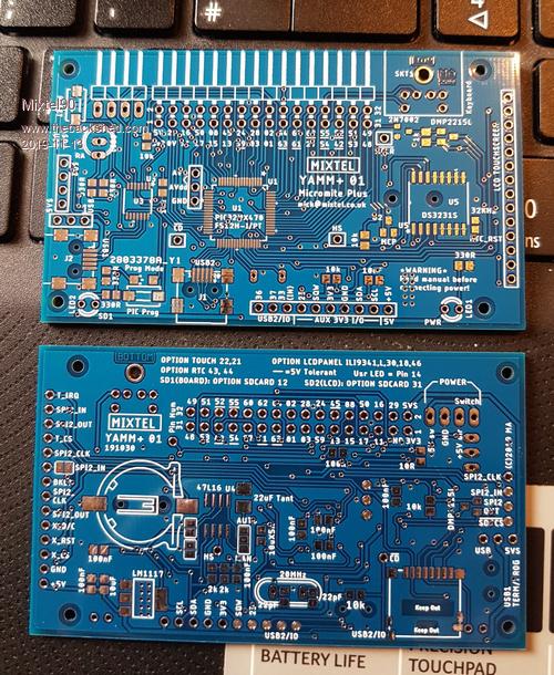 You know when you make a mistake it should always be a big one? This one is a beaut! I've only gone & put the microSD socket on wrong way round... Oh well, the touch display SD socket should still be fine so these boards should be ok with that limitation. We'll see when I manage to get one built up. Edited 2019-11-13 09:59 by Mixtel90 Mick Zilog Inside! nascom.info for Nascom & Gemini Preliminary MMBasic docs & my PCB designs |
||||
| Mixtel90 Guru Joined: 05/10/2019 Location: United KingdomPosts: 5731 |
Things are moving on. Slowly. Still collecting parts to build up the first of the YAMM+ 01 boards. I've not been wasting time though, having built a vacuum pick-up tool and done a little more SMD soldering practice. I mentioned a second PCB at the beginning of the month. Well, I have a sort of design for one now. It's intended as a local IO board for small industrial control. Tentative name is YAMM+ 02, as it's basically part of the same system. A lot of this is still in the "ideas" stage when it comes to software, especially the watchdog function. That would be written in GCBasic as I'm proposing an 8-pin PIC to save on board space. * Powered from 24VDC. Contains regulation down to 5VDC. Gets 3.3VDC from the ribbon. * Connects to YAMM+ 01 via a 30-way ribbon (It appears that 16+16-way plugs are like unicorn poo to get hold of). * 5off 240VAC rated output relays (powered at 24V), 4 SPNO, 1 SPCO. All can be monitored using a nc second contact (used internally - not wired out). * 2off 24VDC opto-isolated, unfiltered PWM outputs. Can also be used as active high DC outputs. * 8off 24VDC opto-isolated digital inputs with LED indication. Split into 2 banks of 4, each bank can be wired active high or active low. By changing input resistors they could be different voltages too - just to confuse people. :) * PIC Watchdog, using a single pulsed-low bi-directional line in the ribbon. Mosfet to disconnect all relay supplies on watchdog fault. * Watchdog chip also monitors 24VDC supply voltage. * Opto-isolated 24VDC "High" output on healthy signal from watchdog. LED indication of "Healthy" status. * SPI is available on 5-pin header with +5V and GND. * RS-485 is available on 6-pin header. A link on the header enables 120R terminator. * ICSP header for playing with the watchdog software. * PCB size fits standard DIN rail modular mounts from OKW. I've also pushed the size almost to the limit for the free version of Eagle at 7920sq mm. :) There may still be problems. I'm not sure what current the YAMM+ 01 will draw yet, so the heatsinks on the regulators may be too small. (Pre-reg down to 15V then reg down to 5V. Not enough space for a switcher. :( ). It will have to feed the 2.8" TFT display as I've used the other IO pins. lol The SPNO contacts are because of electrical clearance problems with the NC contact. I could make all the relays SPCO at 30VDC max. I'd like to have included some analogue inputs but I ran out of space and IO pins. That might be for YAMM+ 03, which would probably plug into the SPI and sit alongside this module. :) The schematic and PCB design is more or less done now. I'll probably tweak a few things yet. Mick Zilog Inside! nascom.info for Nascom & Gemini Preliminary MMBasic docs & my PCB designs |
||||
| Volhout Guru Joined: 05/03/2018 Location: NetherlandsPosts: 3540 |
Hi Mixtel90, Some things to consider: - typical relay drivers have a flyback diode across the coil. The relay turns off faster if you have zener diode in series with the diode. The flyback voltage will be higher, and the coil will loose energy faster. Less chance for contact weld when switching off heavy loads. - monitoring mechanical relays: the standard dual pole relays may not have mechanical coupling between the 2 contacts, unless the datasheet says so. If the mechanical coupling is not listed, one contact can weld together, and the other still switch. Safety relays do have mechanically coupled monitor contacts. - you can design a voltage independent digital optocoupler input. There are so called "depletion FET's" that (starting from 2 volts upward) act as a current limiter. Together with a matching gate source resistor you can tune them to i.e. 2mA for the opto coupler. An example is BSP149 (a 200V part). These are often used in the startup circuit of a switchmode power supply. Better look at LND150N3: this is a 1.7mA current limitter to 500V. (connect source to gate). Depending on the input range you want to cover, a solution with a normal bipolar transistor may also work, or a classical JFET. - for the optical isolated PWM outputs used digital optocouplers (i.e.6N137). Normal optocouplers will be too slow, and even if you get it working, the delays change with temperature. Not good for PWM. - for the mechanical relays you may want to look into relays with a "gold flash" on the contacts. If they are used at low currents, gold contacts will ensure good switching (i.e. to a PLC input). If used at high currents, the gold will vapourize, leaving the underlaying contact material to do the job (silver or tin based). For controlling relays, motors, bulbs etc.. - I would design the power system to use 24V for the mechanical relay coils, and use a simple switcher to get to 5V. (MC34063 or so). Use that to backlight the LCD, RS485, optocouplers, and make 3.3V in a linear regulator for the MM+/LCD/SD card/real time clock. - Mechanical relays have specification for isolation. The coil to contact isolation is important. But in your case, using the second contact for monitoring, the contact to contact isolation must be checked. Also the clearance you can achieve in the layout. - re analog inputs: if you are isolating inputs and outputs, you must also isolate analog inputs. That is not simple. You often need isolated power for the input circuit. - if you want to use this in industrial systems, PLC's have active high inputs that 'ignore' any current into them less than 2mA (for 2 wire sensors). Interesting project... Volhout Edited 2019-11-24 03:25 by Volhout PicomiteVGA PETSCII ROBOTS |
||||
| Tinine Guru Joined: 30/03/2016 Location: United KingdomPosts: 1646 |
My preference: CPC1708.pdf CPC1709.pdf CPC1966.pdf CPC1998.pdf |
||||
| Mixtel90 Guru Joined: 05/10/2019 Location: United KingdomPosts: 5731 |
Standard relay driver chip with built-in diodes. Simply to save on PCB area, of which there isn't all that much. lol Mechanical relays in sockets so that they can be easily swapped on site. Monitoring is a nc contact so that removed relays are detected. The relays I considered are Finder 40.52 series. 5V/5mA minimum load 8A resistive max. I'm aware of guided contact relays, but as it's very rare to find a standard PLC that uses them (are there any?) I decided they weren't worth the extra cost. Safety relays wouldn't normally be used in this position and probably shouldn't be driven as they are here anyway. I hadn't thought about voltage-independent OCs. Hmmm.... For the digital input arrangement I shamelessly copied some of the "intelligent relays". I like being able to have half the inputs pull-up and half pull-down or on 2 different supplies (normally the same voltage though!). :) Opto-isolation for the PWM outputs probably isn't needed really. It would normally be used to drive a spring-return valve so the opto output current is probably too low anyway. I might be better with driver mosfets. Frequency for the PWM in this instance wouldn't usually be very high either - probably well within the limits of any mid-range opto. They are quite often pretty crude - they don't care if the motor buzzes a bit! I'd *love* to have designed the PSU that way but ran out of board space. :) I tried to fit a switcher in, but would have had to sacrifice too much. 72mm x 110mm really is the limit, otherwise I can't use Eagle and this is just another Eagle learning project really. :) Track clearance for the contacts should be fine, especially with a conformal coating. Relays *state* contact-coil for 6kV and 1kV AC across open contacts. The terminal distance from pole to pole is greater than between open contacts, but a voltage isn't stated. This really is a problem and is one of the reasons why I may never build this. At least, not as it is now with relay monitoring. In my previous life as a control panel designer I never liked putting mains and ELV on adjacent relay contacts, even if the data sheet said it's ok. The only time I've been happy is with the outside poles of 3-pole and 4-pole relays, with the inner poles unused. I'm retired now so I'm not really bothered what's going on in that world. I'm only playing now. :) Sorry, Tinine, but I deliberately wanted mechanical relays here. As I pointed out above, I could do this as a 30VDC system with 5 c/o relays. I *could* use a pair of SSRs for each, but no-one expects a "nc" contact to be open on power failure. Not bothering with analogue inputs at this stage. They are a lot of hassle and use up too much board space. That's not to say that a couple of 4-20mA loops wouldn't have been nice... Edited 2019-11-24 05:07 by Mixtel90 Mick Zilog Inside! nascom.info for Nascom & Gemini Preliminary MMBasic docs & my PCB designs |
||||
| Tinine Guru Joined: 30/03/2016 Location: United KingdomPosts: 1646 |
So no zero-volt switching for AC loads. |
||||
| Mixtel90 Guru Joined: 05/10/2019 Location: United KingdomPosts: 5731 |
Nope, sorry, not in this version of the experiment. :) I started off with the idea of using relays and monitoring them. That was the original concept and drove the idea. There are 5 relays simply because I was experimenting to see how many I could squeeze onto the pcb together with the ribbon connector, driver chip, a useful number of inputs and the terminals. Much as I like zero voltage switching, the original design wasn't really intended to be actually useful. lol As my main interest was in control circuit design and that was mostly on 24VDC, I used a lot of relay outputs and I suppose this is a bit of a hangover from that. I rarely switched mains voltage directly from the outputs of PLCs as I usually needed more than the 0.5A or so that you could get from the (very expensive) SSR outputs at the time. Relay output PLCs were so much cheaper and worked on both AC and DC. You might be pleased to hear, though, that I have thought about a system using SSRs, incorporating output monitoring. A couple of ideas for that - the obvious multiple opto-isolators or "floating" a PIC chip at mains voltage, connecting the inputs via high value resistors to the SSR outputs (possibly with more protection diodes, although the on-chip diodes seem to be ok for the tiny currents involved) and using a single opto-coupler to send a status message back to the controller. It wouldn't be any use for 3-phase, but I'm not interested in having 415V on my pcb anyway. :) I wanted to use 12V as the supply for this originally. 12v-5V regulation would have been much easier. :) There's a price penalty for 12VDC relays though - 24V are so much more common in control circuits as they are often powered from things like generator starter batteries. Even 110V DC (another common control circuit voltage from switchgear closing/tripping batteries) are cheaper. Additionally, the range of actually available contactors with 12VDC coils is tiny. They'll make them for you, but no-one will stock them. This is another good reason to use SSR outputs, possibly driving 240V external relays if interface to a control circuit is needed. Mick Zilog Inside! nascom.info for Nascom & Gemini Preliminary MMBasic docs & my PCB designs |
||||
| Volhout Guru Joined: 05/03/2018 Location: NetherlandsPosts: 3540 |
Hi mixtel90, You can still add the flyback zener diode. If you are using a ULN2004 alike driver, the internal diodes connect to a COM pin on the package. Do not connect that pin directly, but through a zener diode to the +12V or +24V you use to power the relays. The ULN series can handle 40 volts (max 50 V) so the zener voltage could be 15V, even at 24V relays. I would not use 12V relays. Simply becuase efficiency if not using a switch mode power supply. The 5 relays easily consume 1 watt at 12V when on. Meaning in the linear regulator you also have to dissipate 24-12V ...a watt extra. Since the 24V relays typically have a guaranteed �turn-on voltage of 15V or so you should not worry if the 24V is not accurate (22V or so). b.t.w if heat is something you worry about in this small package: there is a switch mode 7805 regulator that is inside the same package as the TO220 linear part: recommendations R-785.0-0.5. Not cheap though. The 34063 switcher is far cheaper. Regards, Volhout Edited 2019-11-24 19:56 by Volhout PicomiteVGA PETSCII ROBOTS |
||||
| Paul_L Guru Joined: 03/03/2016 Location: United StatesPosts: 769 |
Hmmmmmm ... solid state switches have come a long way. I need to power a total of 10 120 vac water pumps in my geothermal heat pump system ranging from 1/20 Hp to 1/6 Hp or roughly 40 W to 125 W. (TACO 006 through 013 or similiar.) I was planning on using mechanical relays but the IXYS CPC 1998 opto coupled ac power switch is available from DigiKey for less than $8.00 singly. These pumps exhibit a very low starting inrush current for an induction motor due to the loose coupled centrifugal impeller and volute structure. Do you guys have any thoughts about driving the CPC 1998 from a micro and what type of heat sink would be suitable to cool it? I anticipate that the pumps will cycle ON/OFF perhaps 10 times an hour. Paul in NY |
||||
| Volhout Guru Joined: 05/03/2018 Location: NetherlandsPosts: 3540 |
Hi Paul, The question about using the CPC1998 directly driven from a microcontroller and what heatsink can only be answered if you specify the operating temperature range at location where the CPC1998 is located. The part can operate from -40C to +85C but parameters change with temperature. If you can drive the LED with 5mA or more you should be fine, but for 10 that is 10 x 5mA directly from microcontroller IO pins. Then the heatsink: the specified voltage across the CPC1998 is roughly 1V at current around 1A. The 125W/110Vac pump would therefore cause a dissipation of roughly 1.25 watt in the CPC1998. With sufficient air flow that could work without a heatsink at room temperature. 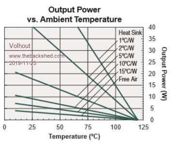 But if your pump should work at 55 degrees C, with 10 of these switches in a little box, each dissipating 1.25watt, the temperature inside the box could be well of 100 degrees C. Total dissipation of the 10 switches, if all on, is around 10 watt. With a small fan that could be done without heatsinking. just place these switched 1/2" appart in a row, and let the fan flow some air between the CPC's. If silence is required, you may have to revert to an ALU block like old audio amplifiers use. Regards, Volhout PicomiteVGA PETSCII ROBOTS |
||||
| Tinine Guru Joined: 30/03/2016 Location: United KingdomPosts: 1646 |
5A continuous with no heat sink and 20A continuous with heat sink. Heat sinking is covered under "Thermal Management" where they also recommend a particular product. They are also zero-volt switching which means that they don't switch until the AC sine wave crosses 0v. Regards, Craig |
||||
| Mixtel90 Guru Joined: 05/10/2019 Location: United KingdomPosts: 5731 |
I doubt if you'd have any problem with those at all. Driving them is identical to driving a LED at 5mA or so - just a suitable resistor from a micro. PIC chips usually handle up to 20-25mA from a single output and will usually source or sink a total of over 100mA so that's probably ok. The LED drops about 1.27V. For something like this I like to put an ordinary red LED in series with the input and use a common resistor. It gives a nice "on" indication when you can't see contacts move and is plenty bright enough at 5mA. :) I think you could probably regard those pumps as almost a resistive load as they are very "lossy". At 120VAC you're probably only drawing a bit over an amp for the 125W rating. The CPC 1998 can handle 5A without a heatsink, so if you fancied putting even a small one on they should be fine. Volt drop is about 1.1V, so even with 1.5A load (even if they had a lousy power factor - it's probably more like 1.2A) it's only dissipating 1.65W in the junction. The thermal resistance is 33C/W to air so that's a temperature rise of 55W above ambient with no heatsink with 1.5A load. Hot to touch, but not dangerous and you shouldn't get that high anyway. Edited 2019-11-25 18:58 by Mixtel90 Mick Zilog Inside! nascom.info for Nascom & Gemini Preliminary MMBasic docs & my PCB designs |
||||
| Tinine Guru Joined: 30/03/2016 Location: United KingdomPosts: 1646 |
 |
||||
| Volhout Guru Joined: 05/03/2018 Location: NetherlandsPosts: 3540 |
@Paul_L, Mixtel90 is right. But please understand that 10 of these CPC's may generate a lot of heat. 16 watt requires a big box with ventilation slots, just to get rid of the heat when ambient temperatures rise to 40C on a summer day. @Mixtel90, You could consider to have the feedback contacts at the mechanical relays checked by the watchdog microcontroller. That offloads the main process (*), and could be done requiring only 1 (i.e. ADC) pin on the watchdog controller. (*) the real time behavior of the main processor should not be bothered or slowed down due turn ON and turn OFF delays of mechanical relays. PicomiteVGA PETSCII ROBOTS |
||||
| Tinine Guru Joined: 30/03/2016 Location: United KingdomPosts: 1646 |
I guess I lost the plot on this one....what is the objective, again? |
||||
| Mixtel90 Guru Joined: 05/10/2019 Location: United KingdomPosts: 5731 |
@Volhout Hmmm... I should have thought of the combined heat output really. I don't know what the ambient is either or how many of what size pumps will run at the same time or how close together the CPCs would be mounted. All these have an effect. Back to my board... The relay feedback contacts are wired back to the YAMM+ 01 so they can be monitored in any way the usr sees fit. However, I just realised that I hadn't included /CS for the SPI port so now the c/o relay isn't monitored now. :) Like I said, I'm only playing. :) The external watchdog PIC is a slave, swapping pulses with the YAMM+ 01. If the input remains high for a preset time the watchdog turns off the supply to the relay coils, dropping them all out. Similarly, if pulses aren't returned by the watchdog the YAMM+ 01 knows that the i/o board is down and can raise an alarm. I briefly considered using this chip to monitor the relays too, but it would need a redesign to get a bigger PIC in. I could still play with PGC, PGD and MCLR though, they are only being used for ICSP... Mick Zilog Inside! nascom.info for Nascom & Gemini Preliminary MMBasic docs & my PCB designs |
||||
| Tinine Guru Joined: 30/03/2016 Location: United KingdomPosts: 1646 |
Gut feeling is that the SSRs won't even get warm to the touch. Regards, Craig |
||||
