
|
|
Forum Index : Electronics : Allans Mad-Inverter Project
| Author | Message | ||||
| Warpspeed Guru Joined: 09/08/2007 Location: AustraliaPosts: 4406 |
Yes, its a bit of a lucky dip. They might have been melting down Fords, or beer cans that particular day. Cheers, �Tony. |
||||
| shallowal Regular Member Joined: 26/07/2018 Location: AustraliaPosts: 58 |
So, after much stuffing around with trying to "tune" the transformer I arrived at a solution of using a 4uf starter cap across the secondary which seems to give a peak amplitude of somewhere in the 65-85Hz range, but it's definitely very flat in that range and drops off significantly outside it. Just to confirm my procedure. Use a sinewave generator (Mines a DSO Quad portable oscilloscope) to create a variable frequency sinewave Use a scope to monitor the amplitude/frequency) of the signal and adjust for maximum amplitude Add/remove capacitors across the terminals to maximise the signal at 75Hz. Connect this lot to the secondary (240Vac) winding with nothing else connected. Phew!!.  Allan Allan |
||||
| shallowal Regular Member Joined: 26/07/2018 Location: AustraliaPosts: 58 |
I had forgotten and only just now noticed that I had wound my choke on a pair of the Aerosharp choke cores, but as I previously mentioned, I only had 16mm wire so doubled it up to achieve a pair of 9 turns. I've got the cores arranged side by side rather than back to back as Mark had shown here: https://www.thebackshed.com/forum/ViewTopic.php?TID=11564&P=2#139534 I just tried measuring it with my el-cheapo ebay component tester and it showed 0.05mH and 0.4 ohms. Allan |
||||
| Warpspeed Guru Joined: 09/08/2007 Location: AustraliaPosts: 4406 |
O/k 16mm sq is good for at least 80 amps and x2 that 160 amps running warm. Nine turns is not a lot so try a slightly smaller air gap say using 1.0mm spacers. That should produce a bit more than 50uH which might be a better overall tradeoff between inductance and final saturation. 50uH is about the acceptable minimum, but a little bit more is a little bit better. The resonant peak will not be at all sharp, and its quite difficult to decide where the peak actually is. But you are probably very close, and it should work well. Cheers, �Tony. |
||||
Revlac Guru Joined: 31/12/2016 Location: AustraliaPosts: 961 |
Allan, I'm not sure where that noise in the circuit is coming from, Trying to figure that out, looking at your photo it looks like that is the first version of control board..I think, Did you do the mods around the on/off switch? I have also put the 10uf and 104 capacitors under the board. The wires from the Nano to the LCD should be kept away from the metal frame or anything that it might pick up interference from. Mark has suggested using shielded wire, that's something I still have to do when the connectors arrive, also found a good quality PS2 Keyboard cable that should do the job. Another thought, Is there a charge controller connected causing noise? The cap charge resistor I had took about 5 seconds to charge up to 54v, it worked a few times then I had it hang a few times, changed the resistance so it charges fully in a bit over 1.5 seconds, so far its going good. Have tripped the over current a few times before getting it setup correctly. Cheers Aaron Off The Grid |
||||
| shallowal Regular Member Joined: 26/07/2018 Location: AustraliaPosts: 58 |
Thanks for your help Aaron. In answer to your questions: Yes I did the mods around the on-off switch. When the switch is disconnected the resistors pull the EG8010 to the disable condition. I havent noticed any problem with the LCD as yet, but I'll keep your suggestion in mind for when I get everything into its permanent position. I dont have any charger connected while I am testing the inverter as I want it all to be floating so that I dont electrocute myself, or blow up my scope etc. My last efforts included installing a current limiting resistor, but I could not get the board to start as the overcurrent cct would engage on powerup. What resistance did you end up using for limiting the precharge current?. I had a blow up a couple of days ago after testing the system for about an hour with a fan heater as the load. Switched between full power (2400W), half, fan only, and off several times over a period of about an hour without any problem. When I went to switch the system off, I had the heater running on fan only, and as I flicked the output AC breaker to off, all the FETS blew out as well as half the TIP41/42, the IR2110's and a few resistors. Most dissapointing. Waiting for a couple of replacement parts to arrive while working on some tidy up issues and thinking about the precharge setup. Really appreciate your help guys, Allan Allan |
||||
| shallowal Regular Member Joined: 26/07/2018 Location: AustraliaPosts: 58 |
Oh!, Forgot to ask Aaron, WRT the capacitors, do you mean that you mounted those on the back side of the control board?. If so, what was the purpose of doing that?. Allan Allan |
||||
| Revlac Guru Joined: 31/12/2016 Location: AustraliaPosts: 961 |
Ok, thats the easy bits, mods are done so no problems there, As this is fault finding I had to ask. Only using your photo as a reference, It looks like there is a jumper on the pins where the NTC should be, and also a jumper on the pins where the CT input is. My preference would be to have those parts in place and doing there job, that would prove that it works as it should. The Precharge current resistor I have at the moment is 3 Ohm 25W, works ok so far using a start button, its just one that I pulled out of something, doesn't mean its the correct one, less than 5 seconds to charge up seems to work. If I have an over current situation or the system hang I would turn off the power to the inverter and leave it for 20 minuets or so then try again later, I'm past that happening now...I hope. Turning off the AC output breaker should be fine, same as turning off an appliance, I haven't encountered a problem like that before and trying to figure that out. Can you get a photo of the control board, the AC end? perhaps we can see something. The capacitors under the board were helpful when long wires were used on the on/off switch, see Here and a bit later Here the EI transformer was making some strange noises until then, couldn't see anything wrong with the waveform and nothing blew up. Others build without the capacitors across the 5v and ground under the switch and are working just fine. Also waiting on parts for the next build, will be testing the control card shortly. Oh. the over current trim pot was set to about halfway, that was good enough to run most things to start with, this might be a little different depending on which CT is used. Cheers Aaron Off The Grid |
||||
| shallowal Regular Member Joined: 26/07/2018 Location: AustraliaPosts: 58 |
Oh yes, I see what you mean about the picture and jumper etc. I have to say that I dont know what that thermistor is meant to be measuring so I have just soldered it onto the control board until I figure out what it's for. While testing, I have the CT and VFB connected and am just using a jumper on the enable/disable pins for the EG8010. I had the current sense pot at about halfway, and intended to look at it's adjustment as one of the final steps of the build. I used a 16 ohm 10W resistor for the precharge and stupidly had it connected across the DC breaker. Of course when things went wrong and I flicked that breaker off, I ended up with a red hot resistor, Ha Ha !!!. I noticed on one of your reference posts that you were discussing the voltage sense resistors. I also had to mess with them to get the voltage in range, but I also changed the transformer to one with only about 7Vac output. I can now adjust the voltage between 190-250+. I think my parts have arrived today so I'll get it back together and take some updated pictures. Allan Allan |
||||
| Revlac Guru Joined: 31/12/2016 Location: AustraliaPosts: 961 |
I just put the thermistor on the one of the heat sink's, It might do something if the other sensors or fan fails. A momentary switch in series with that resistor would be ok, somewhere close to the breaker (mine is a 50A breaker) and you can operate both with one hand, Doing that while filming with a camera was a little tricky though. And I have burnt fingers before checking things for heat.  Everything sounds ok with the rest of it, the only thing I could think of, is to check around the SCR, VFB see if the solder joints are ok, solder joints can fail after a mishap and then cause problems with the new set of components, been there done that. Hopefully this round works for you, fingers crossed. Cheers Aaron Off The Grid |
||||
| shallowal Regular Member Joined: 26/07/2018 Location: AustraliaPosts: 58 |
I think I discovered why I had that last blow-up. 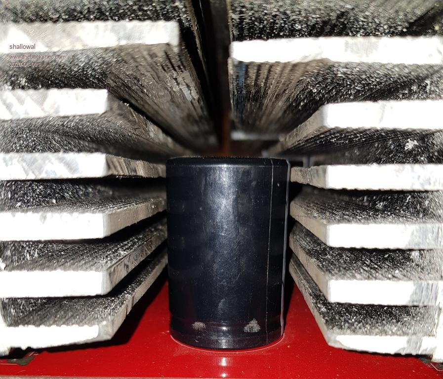 Allan Allan |
||||
| Revlac Guru Joined: 31/12/2016 Location: AustraliaPosts: 961 |
Looks like it needs a bit more clearance between the heat sink and capacitors...would help a little with airflow I'm working on a control board at the moment, checking solder joints, been bitten by bad joints before. Some places (trim pots or any tracks) on the top side of the board where the solder may not have flown through from the bottom, I have just fixed them up just to be sure that there will be no problems there. Might be worth removing the big Capacitors (Carefully) and running the inverter with a current limiting resister, just to be sure everything is working again and to avoid more damage. Don't need to load it with more than 100watts or so to see if its ok. Hope it works for you, looking forward to seeing it going. Edited 2020-06-10 19:21 by Revlac Cheers Aaron Off The Grid |
||||
| shallowal Regular Member Joined: 26/07/2018 Location: AustraliaPosts: 58 |
I did exactly what you suggested Aaron, after discovering this thread: https://www.thebackshed.com/forum/ViewTopic.php?TID=10226&P=5. I'm sorry to say it, but the discussion in that thread gave me great encouragement to persist, and the test regime from Madness was gold. So by using the current limited power supply I discovered that I had a damaged through hole on the Drain of one of the Mosfets, so essentially no connection, and the replacement IR2110 had a faulty output on pin7 thereby preventing the chargepump voltage buildup. Looked good without the powerboard, but was all but zero output when loaded. So now I have got to the point of installing 8 FETs, but no caps and connecting the toroid and examining the waveforms. 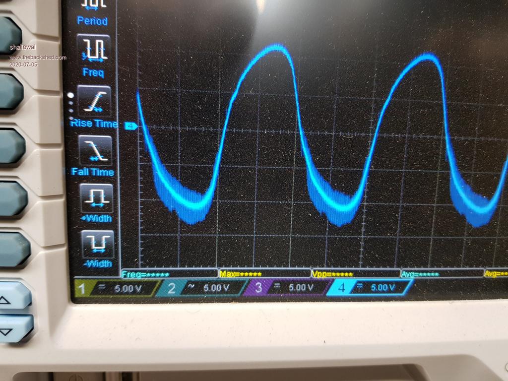 Is that fuzz on the bottom caused by an underrated choke?. 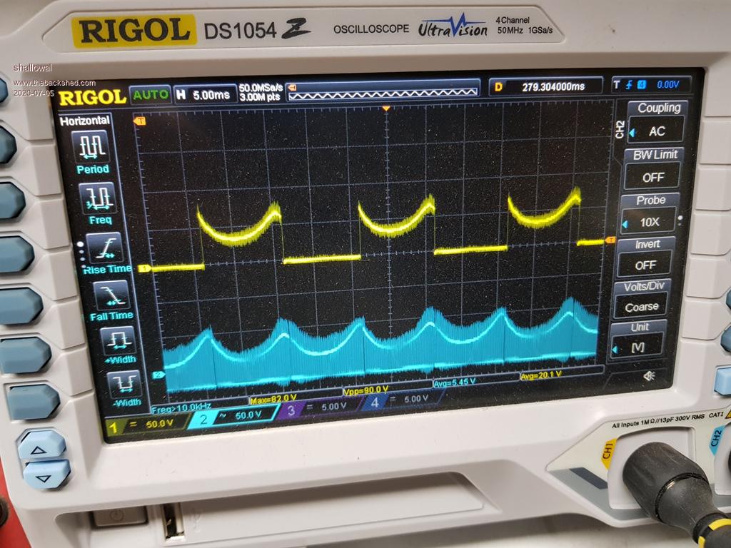 Or is there something else happening somewhere?. Allan |
||||
| Revlac Guru Joined: 31/12/2016 Location: AustraliaPosts: 961 |
Hi Allan, Fault finding after a mishap is often the most difficult part of the project, trying not to burn up all the new components and work done in the process. Can't say I have seen a fuzzy trace like that yet, but I also don't have Good DSO that would have a fast enough sampling rate to see it. I'm not sure if the choke (if underrated) would be doing that, what I did last time at this stage, was to put 1 small capacitor back in (think it was a 120uf all that was handy on the bench) hopefully not big enough to damage the fets if something went wrong, it was just a small effort to help stabilise the DC supply on the power board bridge. Anyone have a different view on this? I will also be doing the same test regime in a week or so... Already made one mistake this week, the 10uf capacitor behind the Tip35c on the power board, I had the bugger the wrong way round.  Now its fixed. Cheers Aaron Off The Grid |
||||
| shallowal Regular Member Joined: 26/07/2018 Location: AustraliaPosts: 58 |
8 FETS installed, unrestrained battery, No Caps, no load. 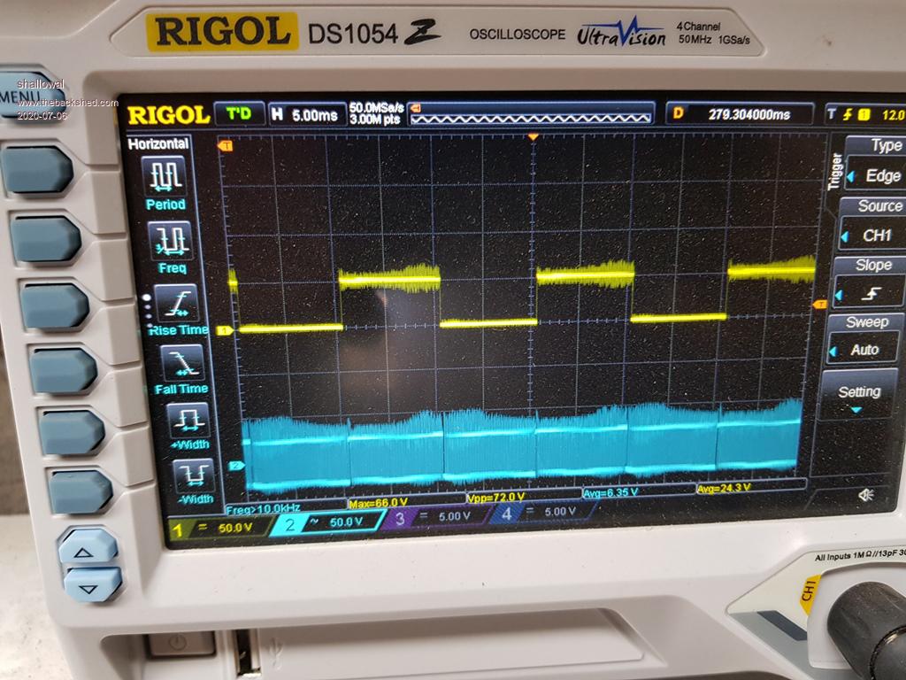 Unrestrained battery, No Caps, approx 1200 Watts load. 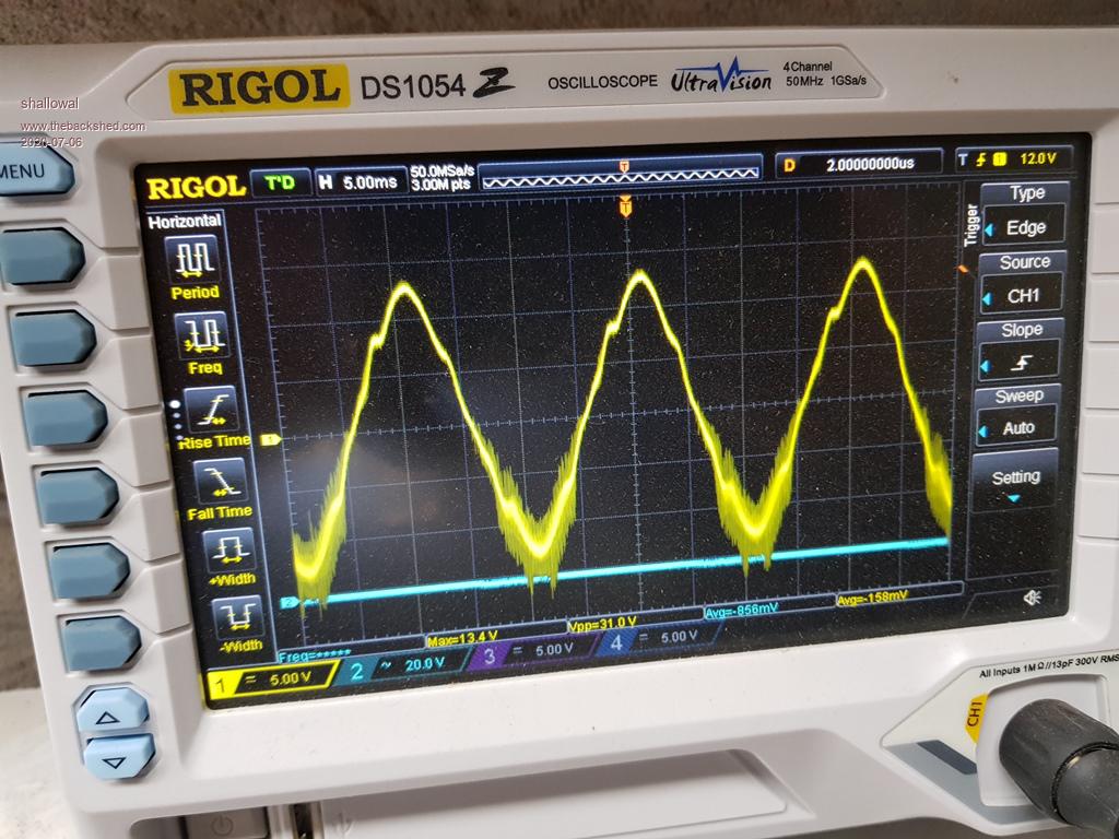 I'm measuring at the output of the voltage feedback transformer. What's with the beard??. Edited 2020-07-06 15:46 by shallowal Allan |
||||
| Revlac Guru Joined: 31/12/2016 Location: AustraliaPosts: 961 |
Trying to interpret what I can see on the SCOPE pictures, the little wobble just below the peak of the wave could be an effect from the load applied and I expect it could be fixed or improved with some adjustment of the choke, air gap or something, not sure what you have there already. I do like the laminated steel cores myself. If you still only have the 475 polyester film capacitor in place, I wouldn't push any more load on it than that 1200w. Now the fuzzy beard bit I'm not sure about, Could it be your scope is picking up noise from something? Also it appears more fuzzy on 1 half cycle than the other, makes me think one leg on the bridge is not working properly, I hope this is not the case. I assume the 2 high speed diodes uf4007 (CR25 27CR) are ok. Don't know why I'm thinking about them. I'm no expert this either. Are the capacitors around the totem pole drivers Ok? I Might have some other idea later. Edited 2020-07-06 19:43 by Revlac Cheers Aaron Off The Grid |
||||
| shallowal Regular Member Joined: 26/07/2018 Location: AustraliaPosts: 58 |
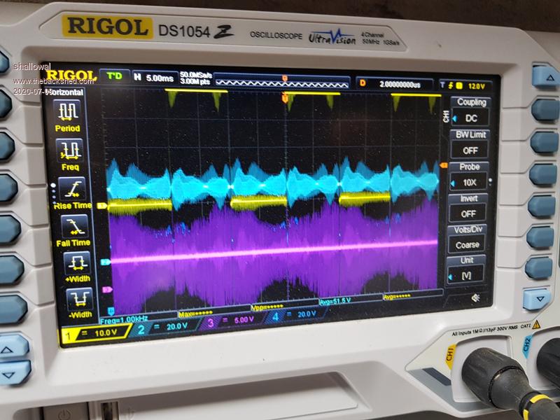 I'm pretty sure the problem is with that 5 volt rail on the EG8010 (purple trace), but now I've blown the EG8010 chip so will have to wait until LCSC ship me the spares I ordered a couple of weeks ago. Allan |
||||
renewableMark Guru Joined: 09/12/2017 Location: AustraliaPosts: 1678 |
Allan, I'm not using 8010 chips now as my unit runs the nanoverter control card. I'll send you my left over chips that are useless to me, pm me your address. You could be waiting months for delivery from china. Cheers Caveman Mark Off grid eastern Melb |
||||
| poida Guru Joined: 02/02/2017 Location: AustraliaPosts: 1389 |
Mark, I still have a few 8010 chips mounted on DIP pcbs that you left me. I tested all and kept those proven to work fine. Maybe you could send those too? Also, I've still got a few nanoverter pcbs available to anyone who wants one. wronger than a phone book full of wrong phone numbers |
||||
| shallowal Regular Member Joined: 26/07/2018 Location: AustraliaPosts: 58 |
That would be very generous of you Mark, thankyou. Allan |
||||
