Notice. New forum software under development. It's going to miss a few functions and look a bit ugly for a while, but I'm working on it full time now as the old forum was too unstable. Couple days, all good. If you notice any issues, please contact me.
Grogster Admin Group Joined: 31/12/2012 Location: New ZealandPosts: 9592
Posted: 05:47am 11 Feb 2020
Copy link to clipboard
Print this post
Hi all.
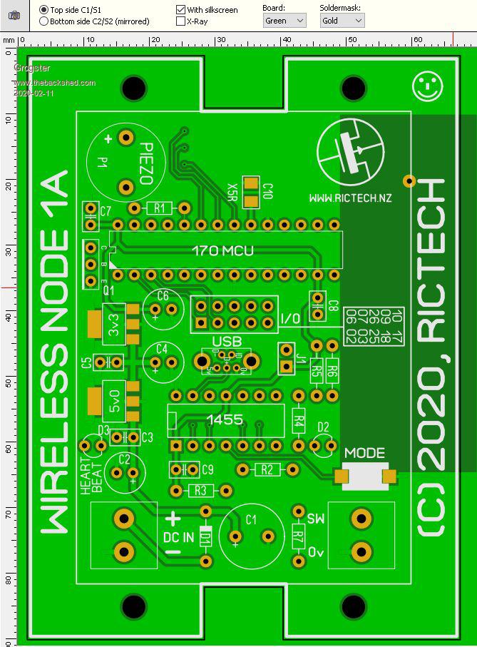
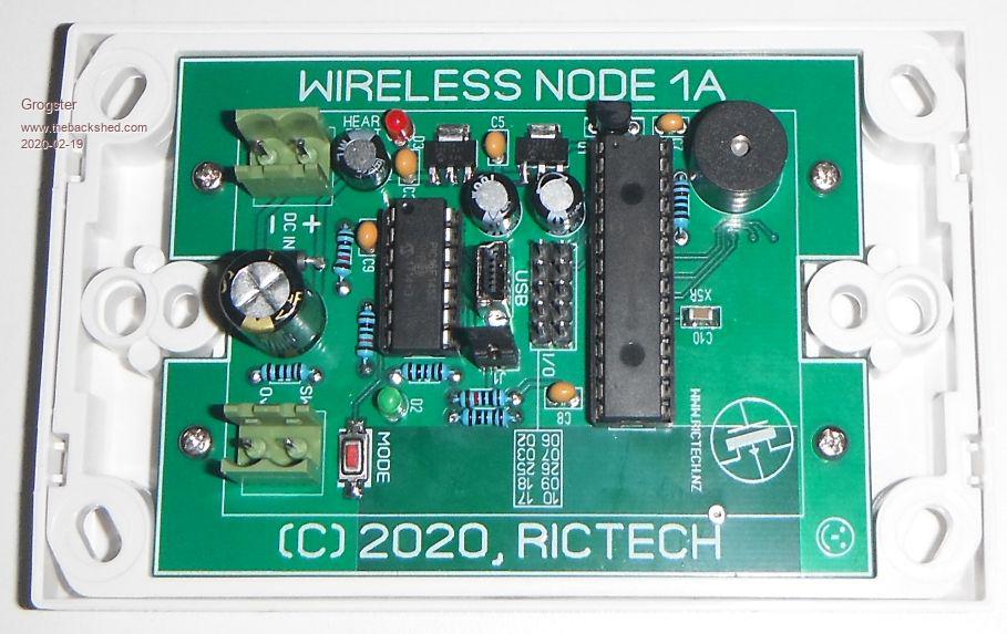
I needed a wireless link that would fit into a standard single wall-plate, so I came up with this:
What I needed, was a simple door-switch that would send a certain code to a base-unit, so I came up with this design, but expanded it so that not only the switch input(SW) is available, but also all of the unused I/O pins for maximum flexibility.
The PCB is designed to fit into a PDL 600-series single wall-plate(a blank one such as 650VH), as in the system I wanted to use it with, all the other call-points etc were on single wall-plates, and powered by a common 12v DC-bus via 4-core security cable.
If anyone is interested in this, I can build a constructors pack and make it available for download from my website along with demo code, BOM etc.
The PCB is still in alpha, so it might have errors, but I will discover these when I build the first few - which have been ordered.Smoke makes things work. When the smoke gets out, it stops!
Chopperp Guru Joined: 03/01/2018 Location: AustraliaPosts: 1094
Posted: 07:55am 11 Feb 2020
Copy link to clipboard
Print this post
Hi Groggs
Good timing. I put in an order for some HC-12's from you yesterday & just sat down to plan out a bit of a MM radio network to get rid of some hard wiring I have around the place.
Your board probably would suit one of my needs.
Could you confirm that the board itself is about 65-66mm wide?
Thanks
BrianChopperP
Bill7300 Senior Member Joined: 05/08/2014 Location: AustraliaPosts: 159
Posted: 09:51pm 11 Feb 2020
Copy link to clipboard
Print this post
Good timing but also good thinking on the housing, Grogs. Let us know once you have the board up and running.
BillBill
Grogster Admin Group Joined: 31/12/2012 Location: New ZealandPosts: 9592
Posted: 11:15pm 11 Feb 2020
Copy link to clipboard
Print this post
@ Chopperp: Yes, 66mm x 89mm. Designed to be a perfect fit in the rear of a PDL 600-series blank wall plate. It will fit either the 650VH or the 650BVH.
Assuming you can get the PDL wall-plate series in Australia? I would expect so - yes? I think that PDL are now called Schneider Electrical, but the codes are still the same so I understand.
@ Bill7300: Will do.Smoke makes things work. When the smoke gets out, it stops!
palcal Guru Joined: 12/10/2011 Location: AustraliaPosts: 1986
Posted: 11:56pm 11 Feb 2020
Copy link to clipboard
Print this post
Clipsal and HPM both have them here in OZ, just a standard wall plate and mounting block if you want."It is better to be ignorant and ask a stupid question than to be plain Stupid and not ask at all"
Chopperp Guru Joined: 03/01/2018 Location: AustraliaPosts: 1094
Posted: 12:15am 12 Feb 2020
Copy link to clipboard
Print this post
Thanks Groggs.ChopperP
Andrew_G Guru Joined: 18/10/2016 Location: AustraliaPosts: 871
Posted: 09:53pm 12 Feb 2020
Copy link to clipboard
Print this post
Groggs, This could be very useful to receive then re-broadcast HC-12 messages around any dead spots in the house. (but I'm not yet sure if SWMBO will allow me to put in more wall plates . . . any chance they could fit behind, say, operative light switch plates - without contravening safety/regs?? - probably not.)
I respect that you have done this for a particular need but two quick comments: - could they (optionally) be powered by 5V (rather than 9 - 12). Is it as simple as jumpering VR1 out? - can the 12V go as far as, say, 12.9V for battery power (if not a separate VR could be used) ?
Cheers,
Andrew
Grogster Admin Group Joined: 31/12/2012 Location: New ZealandPosts: 9592
Posted: 03:37am 13 Feb 2020
Copy link to clipboard
Print this post
Hello.
You COULD hide the PCB in the wall-cavity behind an existing wall-plate, but as you suspect, there are electrical regulation issues there.
Two spring to mind: (1) Separation standards between 230v and low-voltage stuff, and (2) you can't install a plug-pack inside the wall-cavity, and you are also not supposed to drop a low-voltage cable down the same holes in the wall as the 230v stuff - but whatever you do is up to yourself. ;)
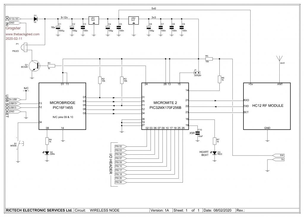
In my case, all the cabling is 0.5mm(well, 0.44mm) 4-core low-voltage security cable that just loops in and out anywhere it is needed, all fed from a master PSU and backup battery. That is is the main reason for the 1000uF cap on the DC input - just to decouple the DC power a bit due to the lengths of the cable runs. With the circuit running from 5v or so, that gives us 7v or so of headroom to play with to allow for voltage-drop on the cable - not that I have ever seen an issue with that at the currents being talked about here.
As to your other question, yes, you can just not install the 5v regulator, and feed the circuit from 5v directly. Voltage-drop on HC12 transmit MIGHT be an issue, cos you then won't have the juicy 1000uF decoupling cap to help decouple the input voltage.
The 5v regulator is my old faithful MCP1703A-50, and it can have up to 16v applied to its input, so that becomes around 16.6v ABSOLUTE MAXIMUM input, taking the 0.6v dropped across D1. It's never a good idea to run things right at the threshold though, so I would not push the voltage up above about 14v maximum. The circuit will be happy at 13.8v - which is a very common single-supply voltage used in many security system installs.Smoke makes things work. When the smoke gets out, it stops!
Andrew_G Guru Joined: 18/10/2016 Location: AustraliaPosts: 871
Posted: 09:42pm 13 Feb 2020
Copy link to clipboard
Print this post
Hi Groggs, Thanks for that. We are about to decide IF we we are to go ahead with building a new house. IF we do I'll be running lots of Cat 5 cable and using HC-12s too. Your wireless nodes might be very useful.
Please keep us posted. Cheers,
Andrew
BrianP Senior Member Joined: 30/03/2017 Location: AustraliaPosts: 292
Posted: 09:52pm 13 Feb 2020
Copy link to clipboard
Print this post
Just thinking (idly)... Would it not be better to run cat6 cabling to future-proof a (little) bit more?
As I said, just thinking...
B
Andrew_G Guru Joined: 18/10/2016 Location: AustraliaPosts: 871
Posted: 10:11pm 13 Feb 2020
Copy link to clipboard
Print this post
Thanks Brian, Good point and I'm always open to ideas. (I had asked here about 18 months ago so I'll do more research before deciding).
I don't want to hijack this thread.
Cheers,
Andrew
Grogster Admin Group Joined: 31/12/2012 Location: New ZealandPosts: 9592
Posted: 02:03am 14 Feb 2020
Copy link to clipboard
Print this post
You're not.
I would also go for CAT6, cos then you can guarantee 1Gb network speed. CAT5 does work at 1Gb if that is all you have, but the speed won't be optimum. 1Gb on CAT5 is still going to be faster then 10/100 on CAT5, but if you end up building a new house, then I would definitely go for the CAT6.Smoke makes things work. When the smoke gets out, it stops!
Andrew_G Guru Joined: 18/10/2016 Location: AustraliaPosts: 871
Posted: 03:06am 14 Feb 2020
Copy link to clipboard
Print this post
Thanks Groggs
Your node is still a great idea. (its also got me thinking of why not a MM with touch screen LCD in there . . .)
Andrew
CaptainBoing Guru Joined: 07/09/2016 Location: United KingdomPosts: 2170
Posted: 10:05am 14 Feb 2020
Copy link to clipboard
Print this post
LOL. CAT6 meh.
I had to throw a link together really quickly and all I had was 4-pair CW1308 telephone cable. I wired it for 1G (not expecting much) thinking if it's no good it'll be alright for an auto-negotiated 100M and even then 10M would be fine (only 30m to the back of the sky box from the backbone). Absolutely no issues whatsoever! 1G sprang up like a good 'un and 2 decades later it is still fine with not so much as a dropped packet.
Guess I am a lucky slob �
word of advice for new-builds/refurbs. Use a colour code. Network cable comes in all colours, choose one and stick with it so you know what is what when opening up an access hatch (and label them to)
jus' sayin Edited 2020-02-14 20:17 by CaptainBoing
Grogster Admin Group Joined: 31/12/2012 Location: New ZealandPosts: 9592
Posted: 06:45am 19 Feb 2020
Copy link to clipboard
Print this post
My PCB's have arrived, so I have built one into a PDL 650VH blank wall-plate:
Demo code:
Install J1 for transmit mode, or leave it off for receive mode. Only the switch input(SW) is supported in this code, but you could easily expand it to do other things, or take advantage of the extra I/O pins.Smoke makes things work. When the smoke gets out, it stops!
RonnS Senior Member Joined: 16/07/2015 Location: GermanyPosts: 121
Posted: 11:18pm 19 Feb 2020
Copy link to clipboard
Print this post
Andrew_G Guru Joined: 18/10/2016 Location: AustraliaPosts: 871
Posted: 12:25am 20 Feb 2020
Copy link to clipboard
Print this post
Hi Groggs,
Very good. Some quick comments/questions: - the Setup and Check subroutines are great - I use Rob's program, but this is a �great option too - where does your switch go? I presume elsewhere? Or, you might be able to use spacers at the four screws with a switch in the outer plate? (in a subsequent version one might find space near the centre to drill a hole for one??) - I'm assuming Jumper 1 is just for your code? One could ignore that and still "suck" and Print to the HC-12? - I'm still struggling to get noise out of a MM - is your piezo loud enough, what ID does it have and from where? {Edit: I just noticed that it is from the 9-12V supply - that would help. I've been restricting myself to 5V }
Cheers,
Andrew Edited 2020-02-20 10:28 by Andrew_G
Grogster Admin Group Joined: 31/12/2012 Location: New ZealandPosts: 9592
Posted: 06:32am 21 Feb 2020
Copy link to clipboard
Print this post
Howdy.
Switch is a reed-switch and magnet on a door. J1 is just so the code knows weather this unit is a transmitter or a receiver. You could just ignore that and do whatever you like.
Most piezo beepers with built-in drivers are designed to run from 12v. They still work at 5v, but they are very quiet. Most of them won't work at all at 3v3.
You need a transistor buffer, which is what I am using in this PCB. The piezo is connected to 12v, and the 3v3 I/O pin on the MM drives the transistor buffer. They are plenty loud enough like that.
Here is updated code, cos I found bugs in the first version I posted above:
This version has a long beep for the door being open, and 2x short beep when the door is closed. Any other message is sucked out of the buffer and disposed of to keep the buffer empty, so you don't get corrupted messages.Smoke makes things work. When the smoke gets out, it stops!
Andrew_G Guru Joined: 18/10/2016 Location: AustraliaPosts: 871
Posted: 11:10pm 21 Feb 2020
Copy link to clipboard
Print this post
G'day, thanks for that Groggs. All good stuff.
Can you let us know if/when you go into "production" (and whether it is a full kit or PCB or what?). I could use a few - but no rush.
Cheers,
Andrew
Chopperp Guru Joined: 03/01/2018 Location: AustraliaPosts: 1094
Posted: 07:10am 22 Feb 2020
Copy link to clipboard
Print this post
Like wise
BrianChopperP
Page 1 of 2
Print this page
The Back Shed's forum code is written, and hosted, in Australia.