
|
|
Forum Index : Microcontroller and PC projects : MM2 Wireless Node 1A....
| Author | Message | ||||
Grogster Admin Group Joined: 31/12/2012 Location: New ZealandPosts: 9066 |
OK, will do.  I have eight PCB's left from the first order, but I will be getting more, as the first two work well with the code above. And you can expand on this concept and perhaps use the extra I/O pins for LED's or other things. Would you prefer just the blank PCB's and a BOM, or a kit? If I offered a kit, would you want the blank wall-plate as part of the kit? Thanks for being interested.  Smoke makes things work. When the smoke gets out, it stops! |
||||
Chopperp Guru Joined: 03/01/2018 Location: AustraliaPosts: 1032 |
Hi Groggs, I would prefer a kit. Not fussy about the wall plate one way or the other. Brian ChopperP |
||||
| Grogster Admin Group Joined: 31/12/2012 Location: New ZealandPosts: 9066 |
Acknowledged. I will prepare something and get back to this thread. Smoke makes things work. When the smoke gets out, it stops! |
||||
| Chopperp Guru Joined: 03/01/2018 Location: AustraliaPosts: 1032 |
Thanks Groggs, ChopperP |
||||
| Grogster Admin Group Joined: 31/12/2012 Location: New ZealandPosts: 9066 |
FULL KIT including PCB, the MM2 170 chip, the 1455 microbridge chip, the HC12 RF module and a blank PDL wallplate to assemble it all into: US$53 including airmail postage. SHORT-FORM KIT with most parts and PCB, but NOT INCLUDING the MM2 170 chip, the 1455 USB chip, the piezo, the HC12 RF module or the blank wall-plate: US$35 including airmail postage. Many people will already have MM2 chips, 1455 microbridge chips and HC12 modules, so the short-form one would suit those people. If you need everything, then the full-kit would cater to that. If those prices are not too scary, I can add them to my website. Let me know your thoughts. Smoke makes things work. When the smoke gets out, it stops! |
||||
| Chopperp Guru Joined: 03/01/2018 Location: AustraliaPosts: 1032 |
Groggs A bit scary :-) I'll take one full kit. If you sell the programmed 1455 chip separately, I'll also have a short form kit. Brian ChopperP |
||||
| Grogster Admin Group Joined: 31/12/2012 Location: New ZealandPosts: 9066 |
I do, but if you want a short-form kit too, I can throw in the programmed 1455 for free. Just for you.  Smoke makes things work. When the smoke gets out, it stops! |
||||
| Chopperp Guru Joined: 03/01/2018 Location: AustraliaPosts: 1032 |
Thanks G. ChopperP |
||||
| Grogster Admin Group Joined: 31/12/2012 Location: New ZealandPosts: 9066 |
Just so you can see where I got those figures from, here is the spreadsheet I used to work it out: 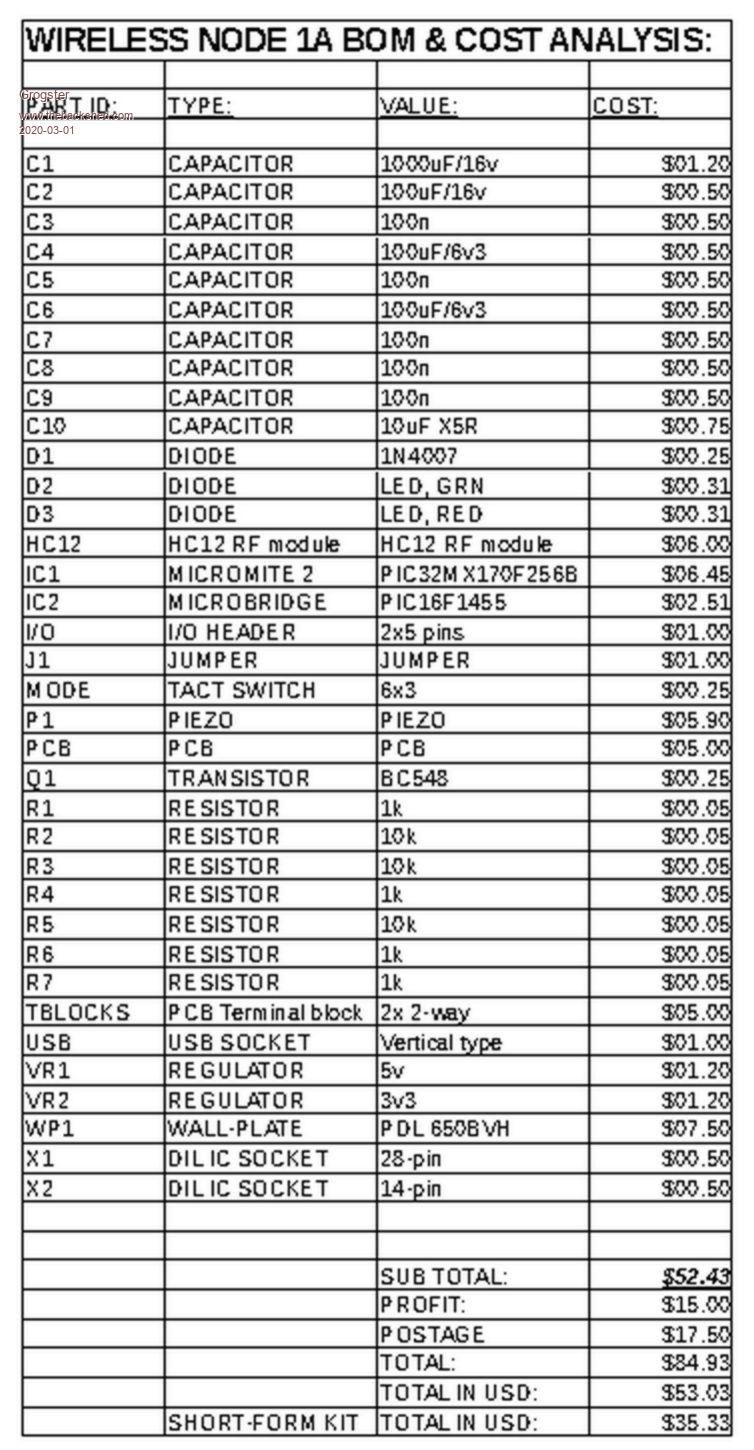 All the line costs for the passives are in NZ dollars, based on Jaycar prices. PIC32 and PIC16 are in NZ dollars, converted from USD on Microchip Direct. This shows how things really DO add up. I am allowing myself a profit of $15 in NZ money for each kit, so I am certainly not milking it. Postage is also in NZ dollars - NZ Post charge quite a bit just for standard airmail now.  Final figures in USD are rounded to the nearest dollar. Current exchange rate to the greenback(USD) is 0.6244 - IE: one NZ dollar is worth 62.44c in American currency. Smoke makes things work. When the smoke gets out, it stops! |
||||
Quazee137 Guru Joined: 07/08/2016 Location: United StatesPosts: 522 |
I am going to do something like this but it is for the condo I'll be getting in the next few weeks. What I will need it to do is for the HC12 on a board like this at the gate and the HC12 on the bike to talk to each other. Gate says "Hi Im the Gate Keeper" Bike says "Mr Q and I are on our way in Please open for us"  A keypad for when Im going for a walk or maybe a picaxe + HC12 in my pocket. Also would like to add a body detector to let me know if any is lurking around. This has the foundation needed to build on. THANKS Quazee137 |
||||
GoodToGo! Senior Member Joined: 23/04/2017 Location: AustraliaPosts: 188 |
Hey Grogs, how much for a pcb including postage to Oz? Cheers! GTG!  ...... Don't worry mate, it'll be GoodToGo! |
||||
| Grogster Admin Group Joined: 31/12/2012 Location: New ZealandPosts: 9066 |
@ Quazee137 - the two versions of this kit will go up on the website soon, if you are interested. What I am interested in, is if the American wall-plate size is the same with the same mounting holes as the Australian/New Zealand ones... I would fully expect that to come back as a "No." Would I be right there? More interesting to know if the PDL blank wall-plate will fit onto the machine-screw mountings for the USA type wall-plate. I expect I would not be that lucky..... @ GTG - $7.50 including air-mail. Cheaper airmail, as I can just put a blank PCB inside an envelope with some cardboard to keep the envelope stiff, and then it can go letter-rate which is only $2.50 vs the airmail bubble-bags @ $17.50 - big difference. I could put up just the blank PCB on my website as a 3rd option too if people wanted just that. Smoke makes things work. When the smoke gets out, it stops! |
||||
| GoodToGo! Senior Member Joined: 23/04/2017 Location: AustraliaPosts: 188 |
Thanks for that Grogs, I'll take a couple of pcbs please! Let me know how to cough up the cash. Cheers, GTG! ...... Don't worry mate, it'll be GoodToGo! |
||||
| Quazee137 Guru Joined: 07/08/2016 Location: United StatesPosts: 522 |
 https://grabcad.com/library/light-switch-plate-1 May have to make an account. I did awhile back look at enclosures for projects. in 3D you have a measure tool. I packed up my measuring tools and don't know which box.  There are so many. There are so many.Later I'll take a pic and drag it in to a few programs with on screen measuring tools. Been a busy time getting Dr appointments and lab test done before the move. All new medical to setup once I'm moved in. |
||||
CircuitGizmos Guru Joined: 08/09/2011 Location: United StatesPosts: 1421 |
This plate covers the box and the edge of the wall around it, so the board itself would have to be smaller than just the plate. That is a toggle switch plate (as opposed to an outlet plate) and the screws pictured attach the plate to the switch NOT the box. Without the switch there, the screws would touch nothing. The better plate to design for would be the blank wall plate. Those screws go into the box. The U.S. setup suffers from the momentum of history. A standard wall box and plate with either a switch or outlet sandwiched between does its job for mains uses, but isn't pretty to design a circuit card for. 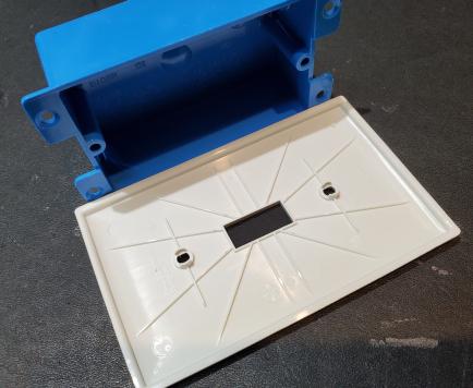 Note the switch plate is larger than the box. The holes on the plate would line up with the switch, not the box. More to note: The blue box is a shallow box. Regular boxes are deeper. 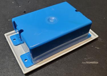 The tabs that you see on this blue box are not standard. There are all sorts of variations. 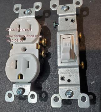 Outlet and switch. The screws that you see captive in each are a standard didstance apart. The plates attach to the outlet and switch in different ways/places. 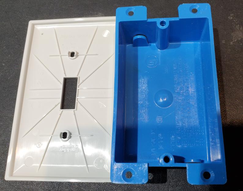 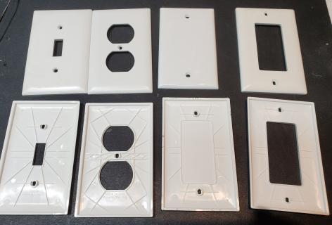 From left to right: Toggle switch plate, outlet, blank, and "Decora". The blank plate is the only one where the holes line up with the box as it is used to cover empty boxes. There are also plates with RJ type phone jacks, coax, etc. Edited 2020-03-03 03:30 by CircuitGizmos Micromites and Maximites! - Beginning Maximite |
||||
| Grogster Admin Group Joined: 31/12/2012 Location: New ZealandPosts: 9066 |
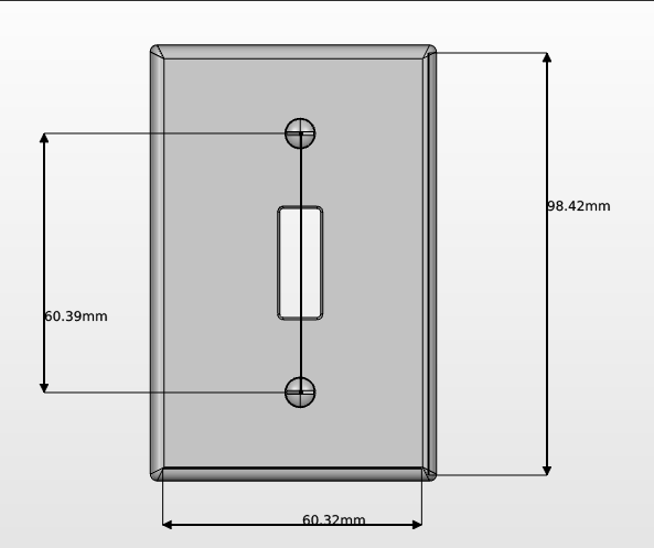
What's the distance between the holes on the American BLANK wall-plate? The PDL blank plate here has its holes 84mm apart for the machine screws, but there are two other holes for screwing the plate directly onto a wall to cover a hole etc, and they are 100mm apart. I don't expect I would be that lucky, that either of those dimensions would agree with the American blank wall-plate would I? Smoke makes things work. When the smoke gets out, it stops! |
||||
| Quazee137 Guru Joined: 07/08/2016 Location: United StatesPosts: 522 |
Here We go 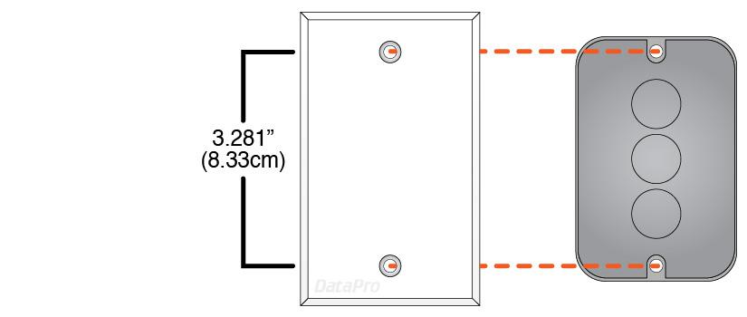 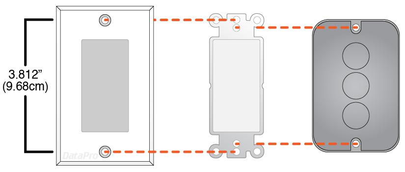 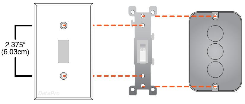 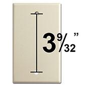 I think that covers it.  |
||||
| Grogster Admin Group Joined: 31/12/2012 Location: New ZealandPosts: 9066 |
Wow! 0.7mm difference between the American and Australian/New Zealand plates' machine screw holes! That would probably mean that the PDL plate would mount on the American flush-box and vise-versa! Perhaps not a PERFECT fit, but it would fit with perhaps a little coaxing.  Smoke makes things work. When the smoke gets out, it stops! |
||||
| Chopperp Guru Joined: 03/01/2018 Location: AustraliaPosts: 1032 |
Hi Grogs How are the kits going? Can't see anything on your website yet.... Brian ChopperP |
||||
| Chopperp Guru Joined: 03/01/2018 Location: AustraliaPosts: 1032 |
FYI Grogs managed to get my order away the other week. Took over 2 weeks to get here though. Just over the ditch I went looking for some blanking plates today but couldn't find the specified ones. All to narrow. Still got to check out Bunnings who one electrical place said should have them. I did manage to spot a reasonable looking case with a clear top & bought one. It had some interesting looking 8mm deep x 2mm wide slots in the bottom for mounting so I assumed so I made up a 3D printed board thingy to fit it. That worked after a couple of much smaller test runs. Fitted nice & snugly. I then thought about how to actually mount the module. My standoffs were buried somewhere then I thought that maybe I could use 3mm rivnuts (nutserts) fitted up the other way. I tried that idea & it worked. I did split the plastic on the first hole I did. Too much pressure. Rest OK. Some piccies below. BTW, the module itself is nice piece of kit. Maybe just needs dab of hot glue on the end of the antenna. Yet to use it in anger. Brian 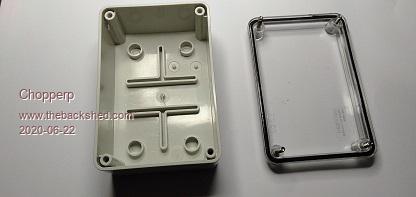 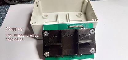 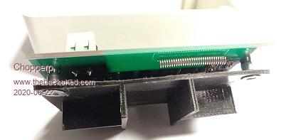 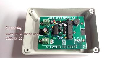 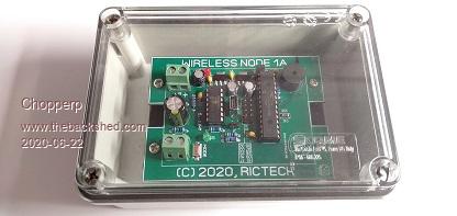 ChopperP |
||||
