
|
|
Forum Index : Electronics : 150V 45A MPPT - roll your own
| Author | Message | ||||
| wiseguy Guru Joined: 21/06/2018 Location: AustraliaPosts: 1018 |
Just revisiting the schematic and I notice the value of R1 looked a bit high. The TLP250 should have a 470R not a 620R, and the pin for pin equivalent opto driver with much improved specs all round is the FOD3182. If the FOD3182 is chosen it should have a 270R for R1. Despite the fact that the units have been running without issue I tend to design for all the worst case figures such as VF - forward voltage drop Max of 1.8V and if given a range of suggested operating conditions ie 10 - 16mA usually choose the middle of the range ie 13mA. For Q4 & Q5, Poida tested and I believe installs & uses the body diode of the FETs acting as a flywheel Diodes for the converter. The board layout could also use suitably rated T0247 Fast or Schottky diodes (usually T0247's are dual diodes) in lieu of the Q4 & Q5 FETs. If TO247 diodes are chosen their reverse voltage must always be greater than the solar panel's open circuit voltage. If at first you dont succeed, I suggest you avoid sky diving.... Cheers Mike |
||||
Bryan1 Guru Joined: 22/02/2006 Location: AustraliaPosts: 1215 |
Well those M4 board connectors turned up today and on opening the package all in one plastic packet and not in packs of 20. Bribed my daughter to do a count and sure enough got 120 of them. Now I did download that MTTP sketch and on reading thru the first part of where the serial stuff is all written is that for the 20x4 serial LCD ? That LCD is one I still have to get so a link to one would be very nice as to ensure I do get the correct on. Cheers Bryan |
||||
| poida Guru Joined: 02/02/2017 Location: AustraliaPosts: 1392 |
The mppt does need a 20x4 LCD and another nano to drive the LCD. The mppt is a bit noisy from the point of view of EMI. I first tried I2C but that is quite sensitive so I have moved to what I call "serial LCD" It's easy to make them, just a bit of wires, a nano and the LCD. You end up with the LCD powered by the mppt, using one of the digital pins for serial data. I love them. No farting about wondering what address the I2C device is supposed to be. (and no random lockups of my inverter, no garbled data on the mppt LCD, etc.) In both the picoverter and the mppt code, the serial LCD data is sent in spare time within the main 20kHz interrupt code. Actually it runs at 19,200 Hz which is 2x 9600 Hz and exactly what the serial LCD wants. wronger than a phone book full of wrong phone numbers |
||||
| poida Guru Joined: 02/02/2017 Location: AustraliaPosts: 1392 |
Thanks for this, Mike. I agree that R1 is best chosen carefully and in accordance with your recommendation. I tested 200V diodes and they work fine. You need to ensure they will handle the current. With a max current of 45 Amps, the TO247 diode (with it's 2 diodes inside) will see 45 Amps. It's not a good idea to assume the load will be shared equally. I chose 150V or 200V diodes that can handle 60 or more Amps for testing. That is the package can handle 2 x 30 Amps. There are two TO247 footprints for two diodes we are over engineering it a bit. But I use HY5110 100V FETs since I had them lying around unused. This brings me to think about voltage ratings for the FETs and DIODES: The mppt will be operating with input voltages less than the array's open circuit voltage. Probably only 80% and it will be at this voltage for a lot of the time. With a solar panel, power (and current) drops off very fast after max power as the voltage rises. At open circuit voltage, there is near zero current. My home system has open circuit of 110V. I use diodes (the HY5110 FETs as diodes) even though they are rated at 100V. I tested them and found they are good to about 110V or a little more. It's no problem and if/when they blow I fix it again. wronger than a phone book full of wrong phone numbers |
||||
| poida Guru Joined: 02/02/2017 Location: AustraliaPosts: 1392 |
I have worked on the mppt code, to add a new function. This new thing will record daily energy totals for 7 days, rolling over the totals each day. You switch LCD view from mppt to daily kW.hr totals by pulling D2 to ground. I found little interest in the D2 override function so I removed that. This frees up a control pin! There is a new function in the menu that must be used to zero the daily totals, this leaves them all = -1.00 As each day comes and goes, D1 becomes = to D0, D2 = D1 etc.. when the rollover happens. I programmed the detection of nighttime as 1 hour of "NITE" mode Once this is detected, the rollover is done. There is also now a need to detect when it's daytime. I look for 1 hour of ABSORB or MPPT or FLOAT mode (i.e. anything not NITE) It seems to work well in testing. It is simple to change the 1 hour time limits if needed. I modified mpptv5_BV_tempco since that is the once I use and expect we all will use it anyway. When you ground D2, you see this: 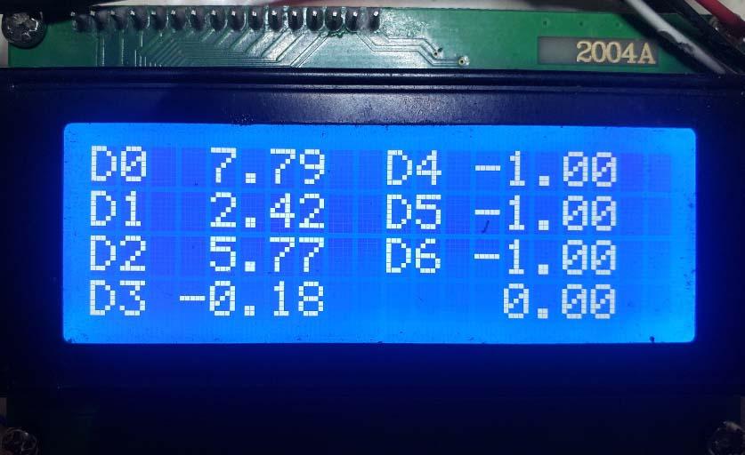 The bottom right number, presently zero will probably will show something like the total energy the mppt has sent to the battery but it's not showing that now. when you let D2 float to 5V, you see the usual display: 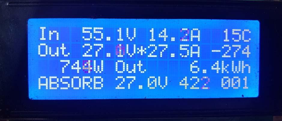 This version of course will retain all your calibration values. mpptv5_BV_tempco_day_totals.zip wronger than a phone book full of wrong phone numbers |
||||
soudirector Newbie Joined: 14/05/2023 Location: NigeriaPosts: 26 |
Hello Great minds!, I am new here. First, I thank everyone of you that contributed to the success of this project is really impressive efforts. I would love to know or have the most updated schematic and the code. This will enable me to study and contribute too. Thanks all how times flies  |
||||
| noneyabussiness Guru Joined: 31/07/2017 Location: AustraliaPosts: 506 |
welcome... updated stuff I think it works !! |
||||
| rogerdw Guru Joined: 22/10/2019 Location: AustraliaPosts: 816 |
Welcome. I don't know if noneyas's link shows it but Poida posted the cct on page 43. Cheers, Roger |
||||
| soudirector Newbie Joined: 14/05/2023 Location: NigeriaPosts: 26 |
Thank you so much. I will go through it how times flies |
||||
| soudirector Newbie Joined: 14/05/2023 Location: NigeriaPosts: 26 |
I find out that there is no Menu buttons for parameter settings maybe it was not design to have one. Is also very important when designing solar charger controller you need to have this in mind Thunder Surge Protection OR Surge Protection against HIGH voltage!!. Using few of TVS capacitors or it diode in parallel will be nice at the solar input. Lastly, SMPS should be use instead of buck converter, all these Chinese buck converter module usually fail at times. Poida, I couldn't get the MCU board from the link you sent. how times flies |
||||
| Ziki_the Newbie Joined: 13/04/2023 Location: YugoslaviaPosts: 28 |
@saudirector No buttons only serial comm. settings. And the most important thing is that this is not a chinese buck. Pozdrav iz Srbije |
||||
| soudirector Newbie Joined: 14/05/2023 Location: NigeriaPosts: 26 |
Added questions , 1, DC/DC from 12v to V? what voltage power the TLP250? 2, Why do we have to 2 5v VR since only one can power both the Brainbox and the Current sensors, NTC? any specific reasons? how times flies |
||||
| pd-- Senior Member Joined: 11/12/2020 Location: AustraliaPosts: 122 |
1 12v > 12v Gate isolation 2 Les noise getting to the cpu , runs cooler , brainbox can be used for other things |
||||
| mab1 Senior Member Joined: 10/02/2015 Location: United KingdomPosts: 175 |
If i can also ask a question related to Sourdirectors Q2: There's a 5v regulator on the nano itself - is there any reason this cannot be be used for the nano & lcd 5v power? Just run a flylead from the 12v to vin on the nano. |
||||
| phil99 Guru Joined: 11/02/2018 Location: AustraliaPosts: 1815 |
It depends on the the installed regulator. For some clones the maximum input voltage is 10V. |
||||
| mab1 Senior Member Joined: 10/02/2015 Location: United KingdomPosts: 175 |
Hmm, very good point Phil - i was forgetting i have clones. The arduino nano datasheet says 6-20v, but the clones? The ones i have say 1117 05 which i guess is lm1117 low drop out 5v and (branded) are rated up to 15v, but these? |
||||
| poida Guru Joined: 02/02/2017 Location: AustraliaPosts: 1392 |
I have found some Nano's 5V regulator are not happy powering the LCD with backlight enabled. Some LCDs are useless inside poorly lit rooms unless their backlight is on. Also, the 7805 gives a decent (i.e. stable) 5V reference for the Nano's ADC conversion. We depend on good voltage and current measurements in this application. In past testing and development I found the onboard regulator can get too hot to touch and I wonder what voltage it is supplying then. wronger than a phone book full of wrong phone numbers |
||||
| flyingfishfinger Senior Member Joined: 12/09/2020 Location: United StatesPosts: 103 |
Well, here's a fun one. I blew up some diodes! My mistake actually, I feel silly. The MPPT has been running great for a year on 2 panels (OC something like 90V) but I really want 3 panels in series (-> 130V). I had upsized the switching transistors to FDH055N15A as planned (150V).... but I forgot to swap out the "diode" transistors and stuck with HY5110 (100V) Attached 3 panels, at the 60 second mark the thing quite spectacularly exploded. Sadly I think there is more damage than just this transistor, there is some charring around the FOD3182's output pins as well, but the 12V output of the isolated regulator is still present. Will have to debug further when I have some time. Question for the group: What transistor would you recommend as a diode that will handle 150V properly? Should I just use two FDH055N15A? EDIT: Looked through the thread and saw suggestions for Vishay VS-60EPU02-N3 or ST STTH6002C. 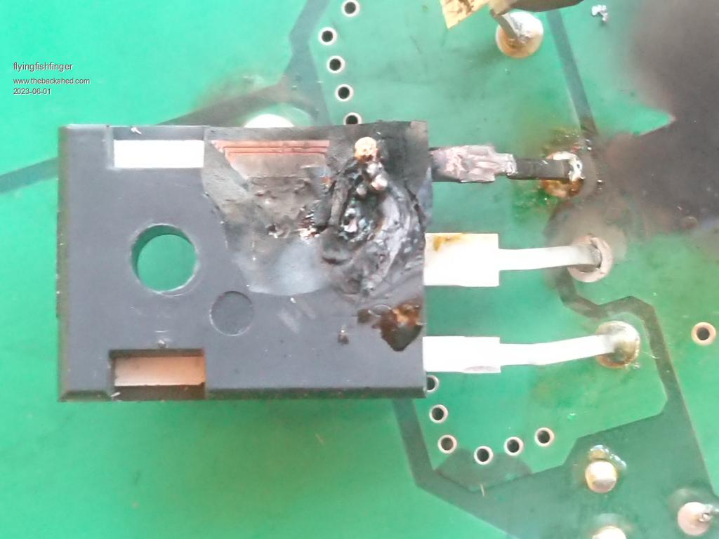 Cheers, R Edited 2023-06-01 07:19 by flyingfishfinger |
||||
| poida Guru Joined: 02/02/2017 Location: AustraliaPosts: 1392 |
FF I would use 200V diodes now. something like STTH6002CW (200V 60A) The only reason I used FETs as diodes is I did not have any suitable diodes on the bench but I had 20 of those HY5110 so I thought "why not?" wronger than a phone book full of wrong phone numbers |
||||
| Solar Mike Guru Joined: 08/02/2015 Location: New ZealandPosts: 1129 |
I would use a Schottky rectifier, as the lower forward voltage drop means less heat. STPS60SM200CW |
||||
