
|
|
Forum Index : Microcontroller and PC projects : MM+ Fast Loading of RLE Images from Flash to SSD1963
| Author | Message | ||||
disco4now Guru Joined: 18/12/2014 Location: AustraliaPosts: 1128 |
In this post Peter Mather developed Cfunctions for data logging to Serial Flash memory chips. These can be conveniently mounted on an existing footprint on the SSD1963 LCD. Routines to write and read data were also included. There is further discussion here about compatability if touch is used. The Cfunctions are compatible with sharing SPI with touch. Some numbers. An 800*480 image at 3 Bytes per pixel for RGB888 colour is 3*800*480=1152000 Bytes. This is 4500 pages when stored on the flash chip. (256 Bytes per page). The 4500 page Image takes about 1050ms to restore to the SSD1963. Most of this time is reading from the Flash chip via SPI. Storing the image on flash as RGB565 requires 2 Bytes per pixel and reduces the size to 3000 pages Without a noticeable change in quality of the image. This reduces the restore time to about 700ms. This posts discusses a few ideas about how to reduce the size of images so they can be quickly loaded to the LCD. Run-Length Encoding is a lossless method of compressing files with repeated Bytes. See wikipedia entry The CFunction SaveImageRLE and CSUB RestoreImageRLE below implement a method of saving images to the flash using RLE to compress the image and restoring to the SSD1963. The method is to use MMBasic LOAD IMAGE command to get the required image on the SSD1963 LCD. SaveImageRLE then saves to the flash. RestoreImageRLE then displays he saved image on the LCD. The image is stored using the following method. The 3 bytes used to define each RGB888 pixel are reduced to 2 bytes encoded as RGB565 ie. RRRRRGGG GGGBBBBB This is then stored using Run Length Encoding (RLE). Each pixel is stored as its two byte RGB565 code, unless a run of two or more identical pixel are detected. In this case only the first two of these identical pixel are written, a count is then made of the number of identical pixel beyond the first two. This count is then recorded using 1,2 or 3 bytes a detailed below. If count <128 then a single Byte is used ie.0XXX XXXX B7=0 and B(6)-B(0) contain the value. If count < 16384 then two bytes are used. Byte 0 has B7=1 in to indicate an addition Byte is required. i.e. Byte 0 is 1XXX XXXX and Byte 1 has B7=0 is 0XXX XXXX .This leaves 14 bits to store the counter. For a counter of > 16383 then three bytes are used. B7=1 for Byte 1 indicating another byte is required. ie. 1XXX XXXX 1XXX XXXX XXXX XXXX All eight bits of Byte 2 are used to store the value, giving a total of 22 bits. This method of encoding is very effective when there are runs of the same pixel. e.g. A full screen of the same colour is stored in 7 bytes. This image from one of the above posts is the candidate used. 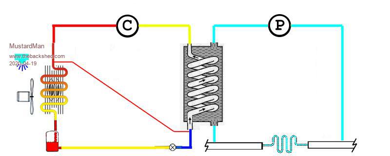 The attached zip file contains the above pump256.BMP It is the schematic from above saved as 256 colours to increase the possibility of runs of pixels the same colour. This 800*320 image is around 311 pages when saved to flash. It restores to the LCD in about 110ms. This refresh looks instantaneous when changing screens. PumpPictures.zip I used XnView as a simple Photo assistant tool. This was used to manipulate the image to 256 colours. When you add it's shell extension, XnShell, it has a lot of common tasks in it's right-click context menu. Google XnView The W25Q64FVSSIG (8MB chip) return this when initialised with Peter's Cfunctions. JEDEC ID = EF4017 F_CS = 58 Memory size is 64 Mbits Memory size is 8 MBytes Valid Page Nos. 0 - 32767 each 256 Bytes So if we allow 400 pages for each image, this means we could have 32000/400 ie 80 different copies of the image save on the flash chip, each displayable in just over 1/10 of a second. This demo program takes Geoff's Pump Controller demo and adds a schematic to the front of it. The Pump controls are accessed by touching the schematic. Once the controls are exited the appropriate image based on the power level is loaded. The code is set for and E100 board. The file pump256.bmp needs to be on the SDCard. The variable eraseandload at line 43 should be initialial set to 1 to load the flash. After the images are stored eraseandload should be set to 0. eraseandload=1 '0 don't erase, 1 erase and load images The demo only saves and restores full screens, however small areas can be selected if desired. So use a bit like BLIT, but with data stored to flash and not memory. F4 H7FotSF4xGT |
||||
| disco4now Guru Joined: 18/12/2014 Location: AustraliaPosts: 1128 |
The source for the CFunction and CSUB is below. /******************************************************************************* * * MMBasic CFunction to save an image displayed on an SSD1963 onto flash chip * which has been fitted to the unpopulated footprint of the SSD1963 * screen. * acknowledgement to Peter Mather for various CFunctions for SSD1963 * and flash chips which have be used to provide many of the routines used. * When Generating the CFunction, use MERGE CFunction mode, and name the CFunction * SaveImageRLE * * Entry point is function * long long main(long long *x, long long *y, long long *width, long long *height, * long long *address,long long *cspin ) * * x,y,width and height defined the area of interest. 0,0,800,480 for the full screen * address is the page number to start writing to the flash chip. * cspin is the chip select pin allocated for the flash chip. (F_CS) 58 on an E100 * * The value returned is the next available page on the flash chip after the image * is saved. You need to manage the layout of the chip manually if you are storing * multiple images. * * The image is stored using the following method. * The 3 bytes used to define each RGB888 pixel are reduced to 2 bytes encoded * as RGB565 ie. RRRRRGGG GGGBBBBB * This is then stored using Run Length Encoding (RLE). Each pixel is stored as * its two byte RGB565 code, unless a run of two or more identical pixel are detected. * In this case only the first two of these identical pixel are written, * a count is then made of the number of identical pixel beyond the first two. * This count is then recorded using 1,2 or 3 bytes a detailed below. * * If count <128 then a single Byte is used ie.0XXX XXXX B7=0 and B(6)-B(0) * contain the value. * If count < 16384 then two bytes are used. Byte 0 has B7=1 in to indicate * an addition Byte is required. i.e. * Byte 0 is 1XXX XXXX and Byte 1 has B7=0 is 0XXX XXXX .This leaves 14 bits * to store the counter. * For a counter of > 16383 then three bytes are used. B7=1 for Byte 1 indicating * another byte is required. ie. 1XXX XXXX 1XXX XXXX XXXX XXXX * All eight bits of Byte 2 are used to store the value, giving a total of 22 bits. * * This method of encoding is very effective when there are runs of the same pixel. * e.g. A full screen of the same colour is stored in 7 bytes. * * V1.0 2020-06-11 Gerry Allardice * ******************************************************************************/ //#define debugging // comment out on final version #define Version 100 //Version 1.0 #include <stdarg.h> #include <xc.h> // Required for SFR defs #include <sys/attribs.h> // Required to use __longramfunc__ #include "../CFunctions.h" //#define PINS64 //E64 driver Comment out for compilation for 100-pin part #define PINS100 //E100 driver Comment out for compilation for 64-pin part #define BITS8 //#define BITS16 #define bclrport *(volatile unsigned int *)(0xbf886134) //latch registers #define bsetport *(volatile unsigned int *)(0xbf886138) //latch registers #define cport *(volatile unsigned int *)(0xbf886230) //latch registers #define cread *(volatile unsigned int *)(0xbf886220) //latch registers #define ctrisinv *(volatile unsigned int *)(0xbf88621C) //latch registers #define cclrport *(volatile unsigned int *)(0xbf886234) //latch registers #define csetport *(volatile unsigned int *)(0xbf886238) //latch registers #define eport *(volatile unsigned int *)(0xbf886430) //latch registers #define eread *(volatile unsigned int *)(0xbf886420) //latch registers #define etrisinv *(volatile unsigned int *)(0xbf88641C) //latch registers #define eclrport *(volatile unsigned int *)(0xbf886434) //latch registers #define esetport *(volatile unsigned int *)(0xbf886438) //latch registers #define DEVID (*(volatile unsigned int *)0xBF80F220) #define writeenable 0x06 #define pageprogram 0x02 #define writestatus1 0x01 #define readstatus1 0x05 #define readdata 0x03 #define fastread 0x0B #define sectorerase 0x20 // 4K 16 pages #define blockerase 0x52 // 32K 128 pages #define block2erase 0xD8 //64K 256 pages #define eraseall 0xC7 #define JEDEC 0x9F #define SPIsend(a) {int j;SPIBUF=a; while((SPISTAT & 0x80)==0); j=SPIBUF;} #define SPIread(a) {SPIBUF=a; while((SPISTAT & 0x80)==0); a=SPIBUF;} //#define SPISTAT *(volatile unsigned int *)(0xbf805810) //SPI status register //#define SPIBUF *(volatile unsigned int *)(0xbf805820) //SPI output buffer #define SPICON *(volatile unsigned int *)(0xbf805A00) //SPI2 control register #1 #define SPICON2 *(volatile unsigned int *)(0xbf805A40) //SPI2 control register #2 #define SPISTAT *(volatile unsigned int *)(0xbf805A10) //SPI2 status register #define SPISTATCLR *(volatile unsigned int *)(0xbf805A14) //SPI1 status clear register #define SPIBRG *(volatile unsigned int *)(0xbf805A30) //SPI2 speed register #define SPIBUF *(volatile unsigned int *)(0xbf805A20) //SPI2 output buffer //Offsets into the persistent RAM of variables #ifdef PINS64 #define RS_Pin_No 27 #define WR_Pin_No 24 #define RS_Pin 0x1000 //bit 13 mask #define WR_Pin 0x0800 //bit 11 mask #define clrport bclrport #define setport bsetport #define port eport #define read eread #define trisinv etrisinv #define RSLo {clrport=RS_Pin;} #define RSHi {setport=RS_Pin;} #define WRLo {clrport=WR_Pin;} #define WRHi {setport=WR_Pin;} #define RDLo (*(volatile unsigned int *)RDclrport)=RDpin #define RDHi (*(volatile unsigned int *)RDsetport)=RDpin #endif #ifdef PINS100 //E100 Board #define F_CS 58 // flashchip CS #define RS_Pin_No 18 //RE8 #define WR_Pin_No 19 //RE9 #define RD_Pin_No 6 // Pin 6/RC1 E100//if not used tie to 3.3v //RB15 pIN 30 #define RS_Pin 0x0100 //b8 portE #define WR_Pin 0x0200 //b9 portE #define RD_Pin 0x0002 //b1 portc #define clrport bclrport #define setport bsetport #define port eport #define read eread #define trisinv etrisinv #define RSLo eclrport=RS_Pin #define RSHi esetport=RS_Pin #define WRLo eclrport=WR_Pin #define WRHi esetport=WR_Pin #define RDLo cclrport=RD_Pin #define RDHi csetport=RD_Pin // #define RDTog RDLo;n=DEVID;n=DEVID;n=DEVID;n=DEVID;n=DEVID;n=DEVID;RDHi; #define RDTog RDLo;n=DEVID;n=DEVID;RDHi; #define WRTog WRLo;WRHi; #define WRTog3 WRLo;WRHi;WRLo;WRHi;WRLo;WRHi; // #define CLKLo bclrport=RD_Pin; // #define CLKHi bsetport=RD_Pin; // #define WRTog WRLo; n=DEVID; WRHi; // #define WRTog WRLo; n=DEVID;n=DEVID;WRHi; #endif #define Both WR_Pin | RS_Pin #define LANDSCAPE 1 #define PORTRAIT 2 #define RLANDSCAPE 3 #define RPORTRAIT 4 #ifdef debugging //Function that gets our address offset so we dont need to pass it in. __attribute__((noinline)) void getFPC(void *a, void *b, volatile unsigned int *c) { *c = (unsigned int) (__builtin_return_address (0) - (b -a)) ; } void pstring(const char *s){ volatile unsigned int libAddr ; getFPC(NULL,&&getFPCLab,&libAddr) ; // warning can be ignored, stupid editor getFPCLab: { } unsigned char * testData = (unsigned char *)((void *)s + libAddr ); MMPrintString(testData); } void p_int(int a,int base){ char b[64]; IntToStr(b,a,base); MMPrintString(b); } void p_float(float a,int m, int n, char c){ // m is the nbr of chars before the decimal point // n is the nbr chars after the point // ch is the leading pad char char b[14]; FloatToStr(b,a, m, n ,c); MMPrintString(b); } #endif /******************************************************************************* * * Write Data to a register on the Chip * ******************************************************************************/ void write_command_data(unsigned int command, int data, ...){ int i; RSLo; va_list ap; va_start(ap, data); port=(command & 0x00FF) | WR_Pin; WRLo; WRHi; // RS low RSHi; for(i = 0; i < data; i++) { port= (char)va_arg(ap, int) | Both; WRLo; WRHi; //RS high } va_end(ap); } /******************************************************************************* * * defines start/end coordinates for memory access from host to SSD1963 * also maps the start and end points to suit the orientation * *******************************************************************************/ void defineregion(long x, long y, long width,long height){ //SSD1963 long x1=x,x2=x+width-1,y1=y,y2=y+height-1; unsigned long xstart,xend,ystart,yend,Vertical,Horizontal; RSLo; if(HRes>VRes){ Vertical=VRes; Horizontal=HRes; } else { Vertical=HRes; Horizontal=VRes; } if(Option->DISPLAY_ORIENTATION!=LANDSCAPE)goto isP; xstart = x1; xend = x2; ystart = y1; yend = y2; if(Option->LCD_CD>6){ //reverse for 7" displays xstart = (Horizontal - 1) - x2; xend = (Horizontal - 1) - x1; } goto setreg; isP: if(Option->DISPLAY_ORIENTATION!=PORTRAIT)goto isRL; xstart = y1; xend = y2; ystart = (Vertical - 1) - x2; yend = (Vertical - 1) - x1; goto setreg; isRL: if(Option->DISPLAY_ORIENTATION!=RLANDSCAPE)goto isRP; xstart = (Horizontal - 1) - x2; xend = (Horizontal - 1) - x1; ystart = (Vertical - 1) - y2; yend = (Vertical - 1) - y1; if(Option->LCD_CD>6){//reverse for 7" displays xstart = x1; xend = x2; } goto setreg; isRP: xstart = (Horizontal - 1) - y2; xend = (Horizontal - 1) - y1; ystart = x1; yend = x2; setreg: port=0x22A ;WRLo; WRHi; // RS low RSHi; port=(xstart>>8 ) | Both; WRLo; WRHi; // RS HIGH port=(xstart) | Both; WRLo; WRHi; // RS HIGH port=(xend>>8 ) | Both; WRLo; WRHi; // RS HIGH port=(xend) | Both; WRLo; WRHi; // RS HIGH RSLo; port=0x22B ; WRLo; WRHi; // RS low RSHi; port=(ystart>>8 ) | Both; WRLo; WRHi; // RS HIGH port=(ystart) | Both; WRLo; WRHi; // RS HIGH port=(yend>>8 ) | Both; WRLo; WRHi; // RS HIGH port=(yend) | Both; WRLo; WRHi; // RS HIGH RSHi; } /******************************************************************************* * * Read full colour RGB888 image displayed on SSD1963 and store it as RGB565 with RLE (Run Length Encoding) * on flash chip. ******************************************************************************/ long long main(long long *x, long long *y, long long *w, long long *h,long long *address,long long *cspin ){ int x1=*x,y1=*y,width=*w,height=*h; int k=0,add,m,pin=*cspin; long pageno=*address; long i,j=0,z=0; unsigned long pixel1,pixel2,firstpixel=0,pcounter=0,rle=0; long n; //Used in RTog macro -don't reuse for anything else or it will take a while to find what you did!!!!!!! unsigned long fhb,fmb, flb, f565h,f565l; //32 bits unsigned char *p; char q; //Keep with screen boundaries if(x1 < 0) x1 = 0; if(x1 >= HRes) x1 = HRes - 1; if(width < 0) width = 0; if(width > (HRes-x1)) width = HRes - x1; if(y1 < 0) y1 = 0; if(y1 >= VRes) y1 = VRes - 1; if(height < 0) height = 0; if(height > (VRes-y1)) height = VRes - y1; i=width*height*3; //Number of bytes. 3 per pixel p=GetMemory(262); //allocate some temporary memory defineregion(x1,y1,width,height); RSLo; port=0x22E ; WRLo; WRHi; // RS low RSHi; trisinv=0xFF; //set pins to read //do { //read in the screen area to be save to flash while (i--) { z++; if (z==1){ RDTog fhb=(read & 0xF8); } if (z==2){ RDTog fmb=(read & 0xFC); f565h=(fhb & 0b11111000) | ((fmb>>5)& 0b00000111); } if (z==3){ RDTog flb=(read & 0xF8); f565l=((fmb<<3)& 0b11100000) | ((flb>>3)& 0b00011111); if (firstpixel==0){ //special case for first pixel // x++; firstpixel=1; pixel1=(f565h<<8)|f565l; p[j++]=f565h; p[j++]=f565l; }else{ //subsequent pixels - pixel1 is populated pixel2=(f565h<<8)|f565l; if ((pixel1==pixel2) && (i!=0)) { //in run length counting if (rle==1){ pcounter++; } if (rle==0){ rle=1; //write the second pixel p[j++]=f565h; p[j++]=f565l; } //pixel1=pixel2; //w++; }else{ // y++; //out of run length count if (rle==1){ rle=0; if ((pixel1==pixel2) && (i==0)){pcounter++; } //add one to count if at end // write the count if (pcounter<128) { // 1byte p[j++]=pcounter; }else if(pcounter<16384){ //2 bytes p[j++]=((pcounter>>7)& 0b01111111)| 0b10000000; p[j++]=(pcounter & 0b01111111) ; }else{ //three bytes p[j++]=((pcounter>>15)& 0b01111111)| 0b10000000; p[j++]=((pcounter>>8)& 0b01111111)| 0b10000000; p[j++]=(pcounter & 0b11111111) ; } pcounter=0; //write the new pixel if not counter as RLE if (pixel1!=pixel2){ p[j++]=f565h; p[j++]=f565l; } pixel1=pixel2; }else{ //just a non matching pixel, no RLE in play // or can be end and possible matching pixel p[j++]=f565h; p[j++]=f565l; // special case of matching pixel as last pixel // need to write counter if ((pixel1==pixel2) && (i==0)){ p[j++]=pcounter; } pixel1=pixel2; } } } // end firstpixel else } //end z=3 //Write the page to flash if we have 256 bytes if (j>255){ k=0; add=(pageno<<8); //convert page number to byte number PinSetBit(pin,LATCLR); SPIsend(writeenable); PinSetBit(pin,LATSET); PinSetBit(pin,LATCLR); SPIsend(pageprogram); SPIsend((add>>16) & 0xFF); SPIsend((add>>8) & 0xFF); SPIsend(add & 0xFF); for(m=0;m<256;m++) { SPIsend(p[k]); k++; } PinSetBit(pin,LATSET); // uSec(1000); do { uSec(100); PinSetBit(pin,LATCLR); SPIsend(readstatus1) SPIread(q); PinSetBit(pin,LATSET); } while(q & 1); pageno++; if (j==256){ j=0; } if (j==257){ j=0; p[j++]=p[256]; } if (j==258){ j=0; p[j++]=p[256]; p[j++]=p[257]; } if (j==259){ j=0; p[j++]=p[256]; p[j++]=p[257]; p[j++]=p[258]; } if (j==260){ j=0; p[j++]=p[256]; p[j++]=p[257]; p[j++]=p[258]; p[j++]=p[259]; } if (j==261){ j=0; p[j++]=p[256]; p[j++]=p[257]; p[j++]=p[258]; p[j++]=p[259]; p[j++]=p[260]; } if (j==262){ j=0; p[j++]=p[256]; p[j++]=p[257]; p[j++]=p[258]; p[j++]=p[259]; p[j++]=p[260]; p[j++]=p[261]; } for(m=j;m<262;m++) { p[m]=255; } } if (z==3) { z=0 ; } } //end while //Write last part filled page to flash if required if (j>0){ k=0; add=(pageno<<8); //convert page number to byte number PinSetBit(pin,LATCLR); SPIsend(writeenable); PinSetBit(pin,LATSET); PinSetBit(pin,LATCLR); SPIsend(pageprogram); SPIsend((add>>16) & 0xFF); SPIsend((add>>8) & 0xFF); SPIsend(add & 0xFF); for(m=0;m<256;m++) { SPIsend(p[k]); k++; } PinSetBit(pin,LATSET); // uSec(1000); do { uSec(100); PinSetBit(pin,LATCLR); SPIsend(readstatus1) SPIread(q); PinSetBit(pin,LATSET); } while(q & 1); pageno++; j=0; } trisinv=0xFF; //set pins to write FreeMemory(p); return pageno; } /******************************************************************************* * * MMBasic CSUB RestoreImageRLE - Restores Run Length Encoded (RLE) file from * Flash and displays on SSD1963 LCD * acknowledgement to Peter Mather for various CFunctions for SSD1963 * and flash chips which have be used to provide many of the routines used. * When Generating the CSUB, use MERGE CSUB mode, and name the CSUB * RestoreImageRLE * * Entry point is function * void main(long long *x, long long *y, long long *width, long long *height, * long long *address,long long *cspin ) * * x,y,width and height defined the area of interest. 0,0,800,480 for the full screen * the width and height MUST match those used when storing the image, however x and y * can be different so its restored in a different position.The area must be with the * screen boundaries. * address is the page number to start reading from the flash chip. * cspin is the chip select pin allocated for the flash chip. (F_CS) 58 on an E100 * * * V1.0 2020-06-11 Gerry Allardice ******************************************************************************/ //#define debugging // comment out on final version #define Version 100 //Version 1.0 #include <stdarg.h> #include <xc.h> // Required for SFR defs #include <sys/attribs.h> // Required to use __longramfunc__ #include "../CFunctions.h" //#define PINS64 //E64 driver Comment out for compilation for 100-pin part #define PINS100 //E100 driver Comment out for compilation for 64-pin part #define BITS8 //#define BITS16 #define bclrport *(volatile unsigned int *)(0xbf886134) //latch registers #define bsetport *(volatile unsigned int *)(0xbf886138) //latch registers #define cport *(volatile unsigned int *)(0xbf886230) //latch registers #define cread *(volatile unsigned int *)(0xbf886220) //latch registers #define ctrisinv *(volatile unsigned int *)(0xbf88621C) //latch registers #define cclrport *(volatile unsigned int *)(0xbf886234) //latch registers #define csetport *(volatile unsigned int *)(0xbf886238) //latch registers #define eport *(volatile unsigned int *)(0xbf886430) //latch registers #define eread *(volatile unsigned int *)(0xbf886420) //latch registers #define etrisinv *(volatile unsigned int *)(0xbf88641C) //latch registers #define eclrport *(volatile unsigned int *)(0xbf886434) //latch registers #define esetport *(volatile unsigned int *)(0xbf886438) //latch registers #define DEVID (*(volatile unsigned int *)0xBF80F220) #define writeenable 0x06 #define pageprogram 0x02 #define writestatus1 0x01 #define readstatus1 0x05 #define readdata 0x03 #define fastread 0x0B #define sectorerase 0x20 // 4K 16 pages #define blockerase 0x52 // 32K 128 pages #define block2erase 0xD8 //64K 256 pages #define eraseall 0xC7 #define JEDEC 0x9F #define SPIsend(a) {int j;SPIBUF=a; while((SPISTAT & 0x80)==0); j=SPIBUF;} #define SPIread(a) {SPIBUF=a; while((SPISTAT & 0x80)==0); a=SPIBUF;} //#define SPISTAT *(volatile unsigned int *)(0xbf805810) //SPI status register //#define SPIBUF *(volatile unsigned int *)(0xbf805820) //SPI output buffer #define SPICON *(volatile unsigned int *)(0xbf805A00) //SPI2 control register #1 #define SPICON2 *(volatile unsigned int *)(0xbf805A40) //SPI2 control register #2 #define SPISTAT *(volatile unsigned int *)(0xbf805A10) //SPI2 status register #define SPISTATCLR *(volatile unsigned int *)(0xbf805A14) //SPI1 status clear register #define SPIBRG *(volatile unsigned int *)(0xbf805A30) //SPI2 speed register #define SPIBUF *(volatile unsigned int *)(0xbf805A20) //SPI2 output buffer //#define SPISTAT *(volatile unsigned int *)(0xbf805A10) //SPI2 status register //#define SPIBUF *(volatile unsigned int *)(0xbf805A20) //SPI2 output buffer //Offsets into the persistent RAM of variables #ifdef PINS64 #define RS_Pin_No 27 #define WR_Pin_No 24 #define RS_Pin 0x1000 //bit 13 mask #define WR_Pin 0x0800 //bit 11 mask #define clrport bclrport #define setport bsetport #define port eport #define read eread #define trisinv etrisinv #define RSLo {clrport=RS_Pin;} #define RSHi {setport=RS_Pin;} #define WRLo {clrport=WR_Pin;} #define WRHi {setport=WR_Pin;} #define RDLo (*(volatile unsigned int *)RDclrport)=RDpin #define RDHi (*(volatile unsigned int *)RDsetport)=RDpin #endif #ifdef PINS100 //E100 Board #define F_CS 58 // flashchip CS #define RS_Pin_No 18 //RE8 #define WR_Pin_No 19 //RE9 #define RD_Pin_No 6 // Pin 6/RC1 E100//if not used tie to 3.3v //RB15 pIN 30 #define RS_Pin 0x0100 //b8 portE #define WR_Pin 0x0200 //b9 portE #define RD_Pin 0x0002 //b1 portc #define clrport bclrport #define setport bsetport #define port eport #define read eread #define trisinv etrisinv #define RSLo eclrport=RS_Pin #define RSHi esetport=RS_Pin #define WRLo eclrport=WR_Pin #define WRHi esetport=WR_Pin #define RDLo cclrport=RD_Pin #define RDHi csetport=RD_Pin // #define RDTog RDLo;n=DEVID;n=DEVID;n=DEVID;n=DEVID;n=DEVID;n=DEVID;RDHi; #define RDTog RDLo;n=DEVID;n=DEVID;RDHi; #define WRTog WRLo;WRHi; #define WRTog3 WRLo;WRHi;WRLo;WRHi;WRLo;WRHi; // #define CLKLo bclrport=RD_Pin; // #define CLKHi bsetport=RD_Pin; // #define WRTog WRLo; n=DEVID; WRHi; // #define WRTog WRLo; n=DEVID;n=DEVID;WRHi; #endif #define Both WR_Pin | RS_Pin #define LANDSCAPE 1 #define PORTRAIT 2 #define RLANDSCAPE 3 #define RPORTRAIT 4 #ifdef debugging //Function that gets our address offset so we dont need to pass it in. __attribute__((noinline)) void getFPC(void *a, void *b, volatile unsigned int *c) { *c = (unsigned int) (__builtin_return_address (0) - (b -a)) ; } void pstring(const char *s){ volatile unsigned int libAddr ; getFPC(NULL,&&getFPCLab,&libAddr) ; // warning can be ignored, stupid editor getFPCLab: { } unsigned char * testData = (unsigned char *)((void *)s + libAddr ); MMPrintString(testData); } void p_int(int a,int base){ char b[64]; IntToStr(b,a,base); MMPrintString(b); } void p_float(float a,int m, int n, char c){ // m is the nbr of chars before the decimal point // n is the nbr chars after the point // ch is the leading pad char char b[14]; FloatToStr(b,a, m, n ,c); MMPrintString(b); } #endif /******************************************************************************* * * Write Data to a register on the Chip * ******************************************************************************/ void write_command_data(unsigned int command, int data, ...){ int i; RSLo; va_list ap; va_start(ap, data); port=(command & 0x00FF) | WR_Pin; WRLo; WRHi; // RS low RSHi; for(i = 0; i < data; i++) { port= (char)va_arg(ap, int) | Both; WRLo; WRHi; //RS high } va_end(ap); } /******************************************************************************* * * defines start/end coordinates for memory access from host to SSD1963 * also maps the start and end points to suit the orientation * *******************************************************************************/ void defineregion(long x, long y, long width,long height){ //SSD1963 long x1=x,x2=x+width-1,y1=y,y2=y+height-1; unsigned long xstart,xend,ystart,yend,Vertical,Horizontal; RSLo; if(HRes>VRes){ Vertical=VRes; Horizontal=HRes; } else { Vertical=HRes; Horizontal=VRes; } if(Option->DISPLAY_ORIENTATION!=LANDSCAPE)goto isP; xstart = x1; xend = x2; ystart = y1; yend = y2; if(Option->LCD_CD>6){ //reverse for 7" displays xstart = (Horizontal - 1) - x2; xend = (Horizontal - 1) - x1; } goto setreg; isP: if(Option->DISPLAY_ORIENTATION!=PORTRAIT)goto isRL; xstart = y1; xend = y2; ystart = (Vertical - 1) - x2; yend = (Vertical - 1) - x1; goto setreg; isRL: if(Option->DISPLAY_ORIENTATION!=RLANDSCAPE)goto isRP; xstart = (Horizontal - 1) - x2; xend = (Horizontal - 1) - x1; ystart = (Vertical - 1) - y2; yend = (Vertical - 1) - y1; if(Option->LCD_CD>6){//reverse for 7" displays xstart = x1; xend = x2; } goto setreg; isRP: xstart = (Horizontal - 1) - y2; xend = (Horizontal - 1) - y1; ystart = x1; yend = x2; setreg: port=0x22A ;WRLo; WRHi; // RS low RSHi; port=(xstart>>8 ) | Both; WRLo; WRHi; // RS HIGH port=(xstart) | Both; WRLo; WRHi; // RS HIGH port=(xend>>8 ) | Both; WRLo; WRHi; // RS HIGH port=(xend) | Both; WRLo; WRHi; // RS HIGH RSLo; port=0x22B ; WRLo; WRHi; // RS low RSHi; port=(ystart>>8 ) | Both; WRLo; WRHi; // RS HIGH port=(ystart) | Both; WRLo; WRHi; // RS HIGH port=(yend>>8 ) | Both; WRLo; WRHi; // RS HIGH port=(yend) | Both; WRLo; WRHi; // RS HIGH RSHi; } /******************************************************************************* *CSUB RestoreImageRLE Restore RLE RGB565 file from flash and display on SSD1963 * * *****************************************************************************/ void main(long long *x, long long *y, long long *w, long long *h,long long *address,long long *cspin){ int t,m; int add,pin=*cspin; add=*address<<8; //convert page number to byte number int x1=*x,y1=*y,width=*w,height=*h; unsigned int brgsave=0; unsigned long i,ch,cm,cl; unsigned long pixel1,pixel2,firstpixel=0,rle=0; unsigned long pcounter=0,pcounter1=0,pcounter2=0,pcounter3=0; unsigned char a; long j,z; if(x1 < 0) x1 = 0; if(x1 >= HRes) x1 = HRes - 1; if(width < 0) width = 0; if(width > (HRes-x1)) width = HRes - x1; if(y1 < 0) y1 = 0; if(y1 >= VRes) y1 = VRes - 1; if(height < 0) height = 0; if(height > (VRes-y1)) height = VRes - y1; i=width*height; defineregion(x1,y1,width,height); RSLo; port=0x22C ; WRLo; WRHi; // RS low RSHi; PinSetBit(pin,LATCLR); //speed is cpuspeed/2*(BRG+1) ???? brgsave=SPIBRG; SPIBRG=1; SPIsend(readdata); SPIsend((add>>16) & 0xFF); SPIsend((add>>8) & 0xFF); SPIsend(add & 0xFF); while (i>0) { if (firstpixel==0){ //special case for first pixel //x++; firstpixel=1; SPIread(ch); ch = ch & 0xFF ; SPIread(cl); cl = cl & 0xFF ; pixel1=(ch<<8)|cl; cm = ((ch << 5 ) & 0b11100000) | ((cl >> 3) & 0b00011100); ch= (ch & 0b11111000) ; cl= ((cl << 3) & 0b11111000); //write to screen i--; port=ch | Both; WRLo; WRHi; port=cm | Both; WRLo; WRHi; port=cl | Both; WRLo; WRHi; }else{ //subsequent pixels SPIread(ch); ch = ch & 0xFF ; SPIread(cl); cl = cl & 0xFF ; pixel2=(ch<<8)|cl; cm = ((ch << 5 ) & 0b11100000) | ((cl >> 3) & 0b00011100); ch= (ch & 0b11111000) ; cl= ((cl << 3) & 0b11111000); if (pixel1==pixel2) { //read the RLE count and write the second pixel //write repeated pixel to screen i--; port=ch | Both; WRLo; WRHi; port=cm | Both; WRLo; WRHi; port=cl | Both; WRLo; WRHi; // now read the RLE counter SPIread(pcounter1); if (pcounter1<128){ pcounter=pcounter1; }else{ pcounter1=(pcounter1 & 0b01111111); SPIread(pcounter2); if (pcounter2<128){ pcounter=(pcounter1<<7) | pcounter2; }else{ pcounter2=(pcounter2 & 0b01111111); SPIread(pcounter3); pcounter=(pcounter1<<15) | (pcounter2 <<8) | pcounter3; } } while ( pcounter--) { //write repeated pixel to screen i--; port=ch | Both; WRLo; WRHi; port=cm | Both; WRLo; WRHi; port=cl | Both; WRLo; WRHi; } //start new pixel firstpixel=0; }else{ //just a non matching pixel, no RLE in play //write to screen i--; port=ch | Both; WRLo; WRHi; port=cm | Both; WRLo; WRHi; port=cl | Both; WRLo; WRHi; pixel1=pixel2; } } } PinSetBit(pin,LATSET); SPIBRG=brgsave; } F4 H7FotSF4xGT |
||||
| disco4now Guru Joined: 18/12/2014 Location: AustraliaPosts: 1128 |
The CSUB PrintFlashPage is a useful utility to use when debugging. It prints a page from the flash in Hex. Usage: PrintFlashPage pageno,cspin where cspin is the CS for the flash chip. ' File PrintFlashPage.bas written 12-Jun-2020 14:42:03 ' CSub PrintFlashPage 00000043 'getFPC 27BDFFF8 AFBF0004 00852023 03E42021 ACC40000 8FBF0004 03E00008 27BD0008 'pstring 27BDFFE0 AFBF001C AFB00018 00808021 00002021 3C059D00 24A50048 27A60010 0411FFEF 00000000 8FA40010 3C029D00 8C42002C 0040F809 02042021 8FBF001C 8FB00018 03E00008 27BD0020 'p_int 27BDFFA0 AFBF005C AFB00058 00803821 3C109D00 AFA50010 8E020030 27A40018 00E03021 0040F809 00073FC3 8E02002C 0040F809 27A40018 8FBF005C 8FB00058 03E00008 27BD0060 'p_float 27BDFFD0 AFBF002C AFB00028 00801821 00A04821 00C04021 7C073C20 3C109D00 AFA70010 8E020034 27A40018 00602821 01203021 0040F809 01003821 8E02002C 0040F809 27A40018 8FBF002C 8FB00028 03E00008 27BD0030 'main 27BDFFC8 AFBF0034 AFB70030 AFB6002C AFB50028 AFB40024 AFB30020 AFB2001C AFB10018 AFB00014 8CB60000 8C920000 3C119D00 262403C4 0411FFB6 00000000 3C049D00 248403C8 0411FFB2 00000000 02402021 2405000A 0411FFC1 00000000 262403C4 0411FFAB 00000000 00129200 3C029D00 8C42001C 02C02021 0040F809 24050005 3C02BF80 8C575A30 24030001 AC435A30 24030003 AC435A20 3C03BF80 8C625A10 30420080 1040FFFD 3C02BF80 8C435A20 7E433C00 AC435A20 3C03BF80 8C625A10 30420080 1040FFFD 3C02BF80 8C435A20 7E523A00 AC525A20 3C03BF80 8C625A10 30420080 1040FFFD 3C02BF80 8C435A20 AC405A20 3C03BF80 8C625A10 30420080 1040FFFD 3C02BF80 8C425A20 24140010 3C11BF80 3C129D00 265203DC 3C159D00 1000004A 26B503C4 AE305A20 8E225A10 30420080 1040FFFD 00000000 8E305A20 321000FF 02002021 24050010 0411FF83 00000000 02402021 0411FF6D 00000000 AE305A20 8E225A10 30420080 1040FFFD 00000000 8E305A20 321000FF 02002021 24050010 0411FF75 00000000 02402021 0411FF5F 00000000 02402021 0411FF5C 00000000 AE305A20 8E225A10 30420080 1040FFFD 00000000 8E305A20 321000FF 02002021 24050010 0411FF64 00000000 02402021 0411FF4E 00000000 AE305A20 8E225A10 30420080 1040FFFD 00000000 8E305A20 321000FF 02002021 24050010 0411FF56 00000000 02402021 0411FF40 00000000 02402021 0411FF3D 00000000 02402021 0411FF3A 00000000 2673FFFF 1660FFBD 02A02021 0411FF35 00000000 2694FFFF 52800003 3C109D00 1000FFB6 24130004 260403C4 0411FF2D 00000000 260403C4 0411FF2A 00000000 3C029D00 8C42001C 02C02021 0040F809 24050006 3C02BF80 AC575A30 8FBF0034 8FB70030 8FB6002C 8FB50028 8FB40024 8FB30020 8FB2001C 8FB10018 8FB00014 03E00008 27BD0038 '.rodata 'nl 00000A0D 'header 2E200A0D 2E2E2E2E 50202E2E 20656761 00000000 'sp 00000020 End CSub e.g. > printflashpage 0,58 ....... Page 0 FF FF FF FF 80 D0 4F EF 5D EF 5D 0 FF FF FF FF 12 EF 5D FF FF FF FF 86 16 EF 5D FF FF FF FF 86 12 EF 5D FF FF FF FF 83 67 EF 5D FF FF FF FF 4 EF 5D EF 5D 0 FF FF FF FF 86 F EF 5D EF 5D 1 FF FF FF FF 82 34 EF 5D EF 5D 0 FF FF FF FF 1 D7 5C 9C D3 7B CE 4A 49 10 A3 0 20 0 20 1 10 A3 31 E9 5B 2C 9C D3 CE 59 EF 5D FF FF FF FF 83 57 EF 5D EF 5D 0 8C 51 6B 4D 31 E9 10 A3 0 20 0 20 2 29 45 52 AA 9C D3 DE DB FF FF FF FF 1 EF 5D FF FF FF FF 82 1F EF 5D FF FF FF FF 0 DE DB 6B 4D 10 A3 0 20 0 20 B 29 45 6B 4D BE 38 FF FF EF 5D FF FF FF FF 83 50 EF 5D BE 38 7B CE 29 45 0 20 0 20 B 29 45 6B 4D CE 59 FF FF FF FF 82 1F EF 5D FF FF CE 59 4A 49 0 20 0 20 0 10 A3 0 20 0 20 D 10 A3 31 A6 DE DB EF 5D FF FF FF FF 83 4E B5 B6 31 E9 0 20 0 20 10 10 A3 Edited 2020-06-12 14:44 by disco4now F4 H7FotSF4xGT |
||||
| The Back Shed's forum code is written, and hosted, in Australia. | © JAQ Software 2026 |
