Notice. New forum software under development. It's going to miss a few functions and look a bit ugly for a while, but I'm working on it full time now as the old forum was too unstable. Couple days, all good. If you notice any issues, please contact me.
rogerdw Guru Joined: 22/10/2019 Location: AustraliaPosts: 801
Posted: 11:45pm 23 Mar 2021
Copy link to clipboard
Print this post
Woah ... that's a lotta toroids Phil.
I think you might have some issues there mate ...
... though come to think of it I might too.
All kidding aside, what are the little ones, I don't recognise them at all.
To answer your question, I don't really know but I understand that with toroids the magnetic field is contained within the windings, so theoretically you should be able to stack them.
I'm not sure what to use or just how to go about it, but I reckon I would fit a spacer of some kind to get a gap of say 25mm or so between each one.
While it would be nice to get some airflow through their centres, the big ones still have their original mounts ... so no air through there.
Then it's a matter of avoiding too much pressure on the windings from one to the next. I wonder if you could use 3 or 4 rubber blocks sandwiched between them which will provide some space and still allow some airflow.
I do recall in the early days of the Ozinverter that some sandwiched a couple of big toroids together but I have no idea if that was a long term thing or just for experimenting.
By the way, are the big ones in the photo 2kW or 3kW Tx's.Cheers, Roger
Haxby Guru Joined: 07/07/2008 Location: AustraliaPosts: 419
Posted: 12:07am 24 Mar 2021
Copy link to clipboard
Print this post
Yes I do have an Aerosharp hoarding problem!
For each phase I'm going to use: Inverter 1=1x3kw aerosharp Inverter 2=1x1.5kw aerosharp Inverter 3=2x12v 150w Talena brand toroid with a couple of extra turns. Inverter 4=1x12v 150w Talena brand toroid with a couple of back-turns.
So 5 toroids per phase = 15 toroids all up.
In theory I also think stacking them should be ok but just checking on the forum before I go too far down that path, buy an enclosure and realise there are problems. It certainly looks wrong.
Warpspeed Guru Joined: 09/08/2007 Location: AustraliaPosts: 4406
Posted: 12:07am 24 Mar 2021
Copy link to clipboard
Print this post
There should not be any external fields worth worrying about, and stacking them pyramid fashion makes perfect sense. Some kind of soft spacer may be a good idea to prevent bruising of any high spots on the windings. These usually come with a "mounting kit" that includes some flat rubber washers, round steel end flanges, and a bloody great bolt.
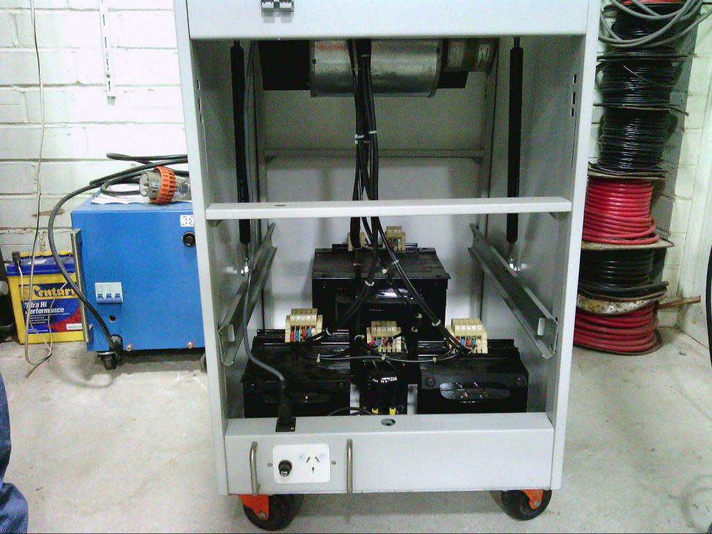
My own preferred method would be to mount the toroids pyramid fashion onto a heavy (6mm?) steel plate secured with some all thread right up through the middle, and fit four castors. It can then all be moved around fairly easily.
That is basically what I did, my outer cover being a resurrected two drawer filing cabinet turned around backwards, so its fully open at the rear.
Another successful method to house very heavy transformers would be to buy an old antique buzz box stick welder, and throw away the guts. That leaves a very robust one foot cube metal box, with ventilation louvers, two wheels and a handle. See the blue box in the picture. That is now a 5Kw three phase dc rectifier with three stacked toroids inside.
Cheers, ĀTony.
Haxby Guru Joined: 07/07/2008 Location: AustraliaPosts: 419
Posted: 12:23am 24 Mar 2021
Copy link to clipboard
Print this post
Thanks Warp, it's good to get reassurance.
Roger, out of the 8 aerosharp inverters I have taken apart, only 2 are the better quality Hefei Ecu-Tamura brand. Doing some digging, I found that they are a Japanese led company.
From the date codes, it looks like aerosharp moved to the better transformer around mid 2010.
rogerdw Guru Joined: 22/10/2019 Location: AustraliaPosts: 801
Posted: 12:14am 26 Mar 2021
Copy link to clipboard
Print this post
Looks like similar numbers for me too Phil, only two of the Hefei Ecu-Tamura ones out of eight inverters.
I was keen for more of the 3kW Eaglerise ones because even though they are wound more roughly, they have far more metal in the core ... and I was unwinding them fully to rewind from scratch.
The Eaglerise ones I have are dated in 2010 but the Hefei Ecu-Tamura have "Date Code: 1022" so not sure how to interpret that. Twenty second week of 2010???
My enquiries locally scored me a bare 3kW core last week. Not sure what the guy was planning to do with it ... maybe he just sold the copper ... but I was very happy to see him turn up with it. And didn't want anything for it either, other than perhaps a good chinwag. Cheers, Roger
Haxby Guru Joined: 07/07/2008 Location: AustraliaPosts: 419
Posted: 11:05am 03 Apr 2021
Copy link to clipboard
Print this post
Righto, I've tested my inverter with light to medium loads, and all looks good.
Time to test with some more demanding loads, namely a 1675W miter saw and a 2200w air compressor.
The startup current will be significant.
I'm using 75A IGBTs, so at 200v input, the theoretical maximum is 15000w.
What's a good way to accurately measure the surge current of the air compressor? If it's more than 7x the 2200w rating, I might have to look into soft starters or different IGBTs.
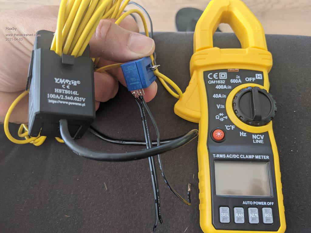
I bought a clamp meter but unfortunately it doesn't have a max-hold feature. Not sure if I would trust it to be responsive enough anyway. I also bought a HSTS016L hall effect clamp rated at 100A, but the analog output seems very noisy as displayed on my oscilloscope. It has a +-600mv output referenced to its 2.5v reference pin. I connected that ref voltage and the analog output to my oscilloscope and then used the math function to subtract the ref voltage from the analog out voltage. The noise is pretty bad. Unworkable really. I've been powering it from the oscilloscope USB output. Maybe it needs a smoother power supply. I'll keep experimenting tomorrow.
Finally I tried the 15A rated LEM sensors that I de-soldered from the DC side of an Aerosharp board, but I can't get that going at all.
Revlac Guru Joined: 31/12/2016 Location: AustraliaPosts: 961
Posted: 11:55am 03 Apr 2021
Copy link to clipboard
Print this post
Motor surge current varies significantly, depending on many factors, build quality, attached load etc. Even an old 4Kw 48v HF inverter can start and run (Brush motors) 1800w power saws and 2400w grinders, it has 75A 650V IGBT's, bus voltage 400v or a bit more. You should not have any problem running these loads with your inverter.
Induction motors can be a different story, Some surges have been quite large, 1600w motor starting under load was 137amp at 50v, 6850w surge 550w running on the Mad Inverter. Other induction motors are not much more than twice the rated start surge.
I have used a (hold peak) clamp meter, it seems to capture the surge in AC or DC, if set up correctly. There are likely a simple way to get some rough measurement.Cheers Aaron Off The Grid
tinyt Guru Joined: 12/11/2017 Location: United StatesPosts: 431
Posted: 01:06pm 03 Apr 2021
Copy link to clipboard
Print this post
Maybe just use a current sense (shunt) resistor and an oscilloscope. Choose resistance value so the loss is minimal and yet high enough to match oscilloscope sensitivity. This way you can see the surge spike waveform. Just make sure the oscilloscope probe gnd is isolated from any other power supply. Edited 2021-04-03 23:08 by tinyt
Haxby Guru Joined: 07/07/2008 Location: AustraliaPosts: 419
Posted: 08:25pm 03 Apr 2021
Copy link to clipboard
Print this post
I haven't had much luck isolating the inverter and/or oscilloscope from ground. I was doing this to measure the high side gate drive. There was lots of capacitively coupled noise from the isolation transformer and from the caps in all the power supply filters. I didn't want to start disconnecting the ground links! Ultimately I bought an isolated probe which is fantastic and keeps things nice and safe. Alas the minimum setting is 50x so of little use for a current shunt.
I might dig out that little $30 battery powered LCD based scope I have and see if that's any better.
Revlac: ok 6850w surge on a 1600w motor, so around 4x the motor rating. I guess things can be much better or worse depending on what is connected to the drive shaft. My air compressor does have an unload valve (or whatever it's called) as most compressors do. Hmmmm definitely worth measuring it. Might just bite the bullet and get a proper fluke clamp meter.
Warpspeed Guru Joined: 09/08/2007 Location: AustraliaPosts: 4406
Posted: 09:21pm 03 Apr 2021
Copy link to clipboard
Print this post
I just used a 100 amp current transformer and a digital oscilloscope set for a very slow single sweep. With the trigger threshold set high enough, I was able to easily capture every single infrequent start up, and seeing up to 19 amp half cycle peak surges when my refrigerator starts up. The rating plate on the fridge says 127 watts running, 350 watts defrost, which indeed it is. But startup is a tad higher than that !
My IGBTs are rated 200 amps continuous, but have a fault current rating of 1,000 amps for one full complete half mains cycle. Yours may be rated at 75 amps continuous, but should easily handle multiples of that for a brief instant. Mosfets just go bang above their max current rating, any peak pulse ratings are for microseconds not for tens of milliseconds.
IGBTs are pretty tough and should serve you well.Cheers, ĀTony.
poida Guru Joined: 02/02/2017 Location: AustraliaPosts: 1389
Posted: 09:13am 04 Apr 2021
Copy link to clipboard
Print this post
These LEM current sensors have 4 wires. Ground, 5V, output, and reference. Give it 5V on 5V pin, with the supply going to ground pin. Now measure the output relative to the reference pin.
The reference pin is internally pulled to 2.5V. And the output is driven relative to that. So put the DSO ground clip on "reference" pin and the DSO signal on the output.
From the photo above the pinout is from left to right 5V, ground, output, reference.
The output will not make much sense if you measure it with respect to ground. It will always be something like 2.5V This is by design.
These devices are nice, they allow isolated current measurement with 5V supply. I can't quite tell from the photo but it might be a CSR 15 which means it gives an output of 2.5V with a bipolar output adding or subtracting from the "reference" 2.5V with a gain of 41.7mV/Amp It does not go rail to rail, i.e. output goes down to ground or up to 5V. There is a limit. If it's the CSR 15, then it can measure +/- 51 Amps or +/- 2.127V relative to the "reference" pin, which is 2.5V
So the output would go from 0.37V up to 4.63V for the -51 Amps to +51 Amps
If the part is a CSR 6, then the measure range is smaller but with better resolution. It has 104.2mV / Amp gain but same deal for output.
It's all relative to the "reference" pin. Edited 2021-04-04 19:15 by poidawronger than a phone book full of wrong phone numbers
Haxby Guru Joined: 07/07/2008 Location: AustraliaPosts: 419
Posted: 10:21am 04 Apr 2021
Copy link to clipboard
Print this post
Poida have you used the LEM sensors on DC or AC successfully? Or both?
It's a CASR 15-NP part number. It was in the DC section of the inverter (from memory) but I popped open the casing and I saw a coil so i was puzzled on how it could measure DC current.
It's possible I may have blown it up. I have many more on hand and will give them another go.
poida Guru Joined: 02/02/2017 Location: AustraliaPosts: 1389
Posted: 10:32am 04 Apr 2021
Copy link to clipboard
Print this post
I've used them with DC and AC. The frequency response is from DC to about max. 300kHz so it's good for the sort of things we are doing here (with 20kHz switching)
These parts cost about $20 AU from RS components I think they are worth the time to remove from the boards.
How they work:
a ferrite core concentrates the magnetic field of the current conductor through a small space where a hall effect sensor is located. An opamp is then used to create a magnetic field to oppose this and the opamp output is used as the sensor output.
It's not as fast as a simple current transformer but it does DC. They are lower noise than the Allegro parts. But just as easy to use.wronger than a phone book full of wrong phone numbers
Haxby Guru Joined: 07/07/2008 Location: AustraliaPosts: 419
Posted: 11:45pm 04 Apr 2021
Copy link to clipboard
Print this post
Thanks Poida, I had written them off after seeing the internal coils. Now I can see that they are quite an ingenious part.
Haxby Guru Joined: 07/07/2008 Location: AustraliaPosts: 419
Posted: 04:31am 15 Apr 2021
Copy link to clipboard
Print this post
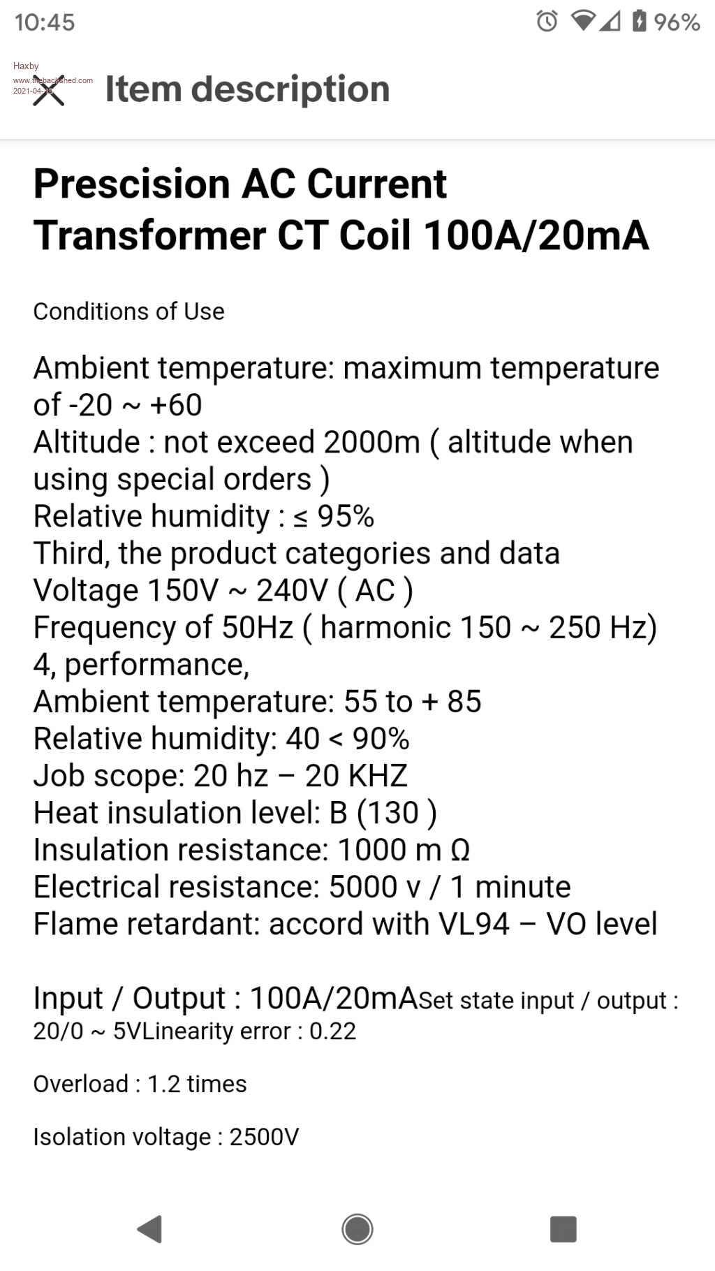
Ok a 100A to 20ma current transformer was delivered to me today.
I set it up on a cut extension cord with a 10 ohm resistor across DSO probe, parallel with the CT output. Just a single loop of active wire went through the centre of the CT.
So v=IR 200mv=10ohm x 20mA So 100A full scale should be 200mV on the oscilloscope. Right?
Well that's not at all what I get.
First a 2000W cheap heater:
My clamp meter shows 8.6A which is close enough to 2000w so I trust it's accurate.
The DSO shows around 120mv peak, so around 80mV RMS.
Why the huge discrepancy?
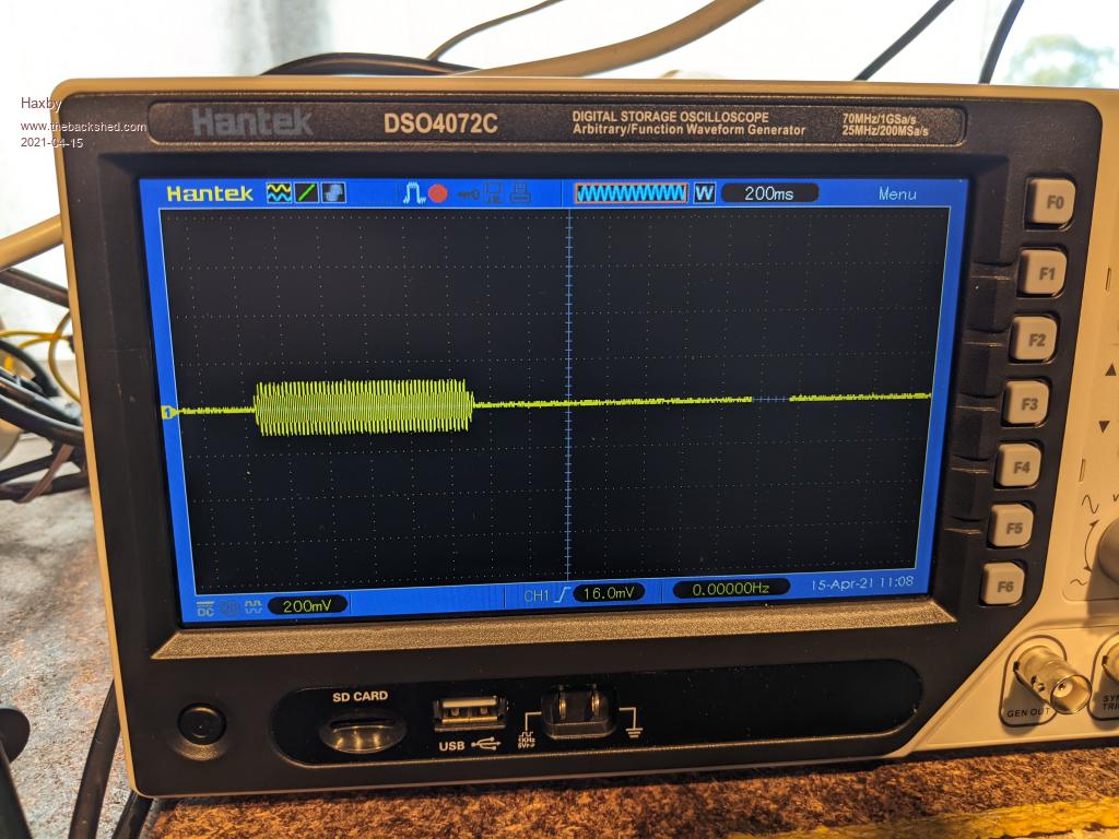
Anyway here are some more screenshots for those interested. Based on the 2000w heater baseline measurement, I'm reading the scope as 20A per division. I have kept all scope settings the same for all 3 appliances.
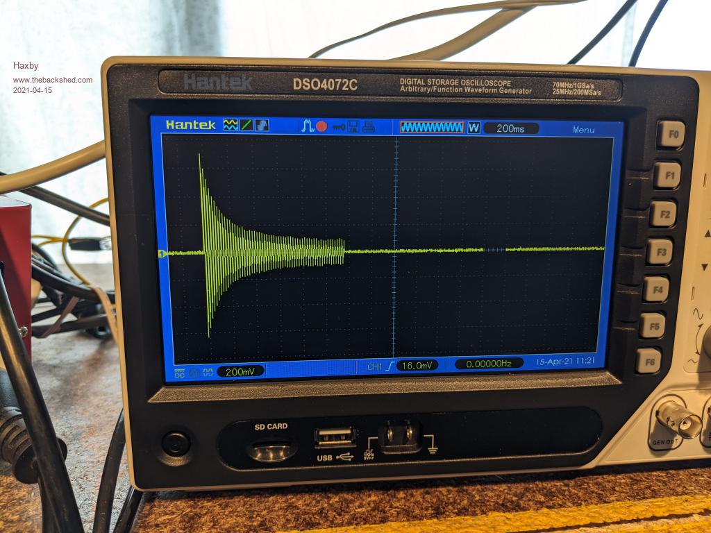
Here is the 2000w AEG brand belt drive 50L air compressor starting up. Looks like around 50A peak:
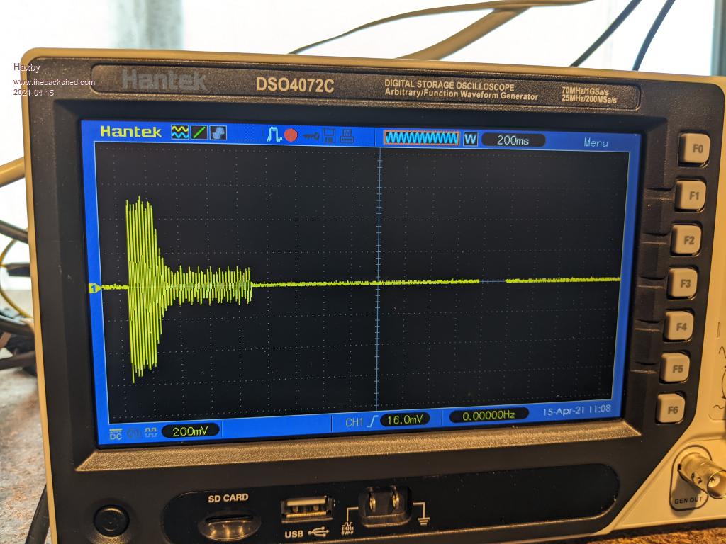
And here is a miter saw spinning up from standstill. Woah, 70A!
Edited 2021-04-15 15:00 by Haxby
Haxby Guru Joined: 07/07/2008 Location: AustraliaPosts: 419
Posted: 05:06am 15 Apr 2021
Copy link to clipboard
Print this post
Here is the spec sheet of the CT.
Warpspeed Guru Joined: 09/08/2007 Location: AustraliaPosts: 4406
Posted: 06:23am 15 Apr 2021
Copy link to clipboard
Print this post
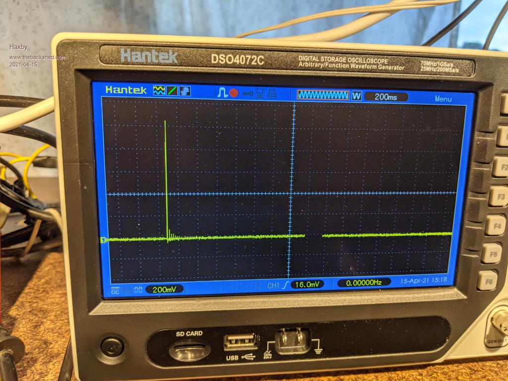
That second picture looks like my refrigerator starting up. I am seeing 19 amp peak inrush for a 127 watt compressor which does run at half an amp rms after about one second running.Cheers, ĀTony.
Haxby Guru Joined: 07/07/2008 Location: AustraliaPosts: 419
Posted: 07:07am 15 Apr 2021
Copy link to clipboard
Print this post
Here is my pesky isolation transformer. It's the one that trips my RCBO sometimes. It needs a soft starter. It draws just over 100A for a very short time.
Murphy's friend Guru Joined: 04/10/2019 Location: AustraliaPosts: 584
Posted: 07:37am 15 Apr 2021
Copy link to clipboard
Print this post
I just used a relay with suitable N/O contacts that were bridged by a 33R/10W resistor. This was in series with the mains input. The transformer had a low voltage secondary, rectified & with a capacitor on DC side that powered the relay coil. The transformer would start via the resistor until the relay pulled in and shorted it out. That works automatically and has so for many years on my big power supply transformer.
Warpspeed Guru Joined: 09/08/2007 Location: AustraliaPosts: 4406