
|
|
Forum Index : Microcontroller and PC projects : How to connect multiple Nunchuks to CMM2
| Page 1 of 2 |
|||||
| Author | Message | ||||
| William Leue Guru Joined: 03/07/2020 Location: United StatesPosts: 411 |
I want to connect 2 Nunchuks to the CMM2. However, the Nunchuk connector appears to have only room for a single Nunchuk. I have some clone Nunchuks, not original Nintendo. Maybe the original ones had a provision for chaining two or more at the plug? Any hints will be much appreciated. -Bill Leue |
||||
| mkopack73 Senior Member Joined: 03/07/2020 Location: United StatesPosts: 261 |
the nunchucks (and Wii Classic controllers) talk over a protocol called I2C. The CMM2 exposes 1 of the I2C lines (port 3) to the front connector... To hook up additional you have to interface with the GPIO pins on the back to get at the other I2C ports pins. Hopefully somebody will come up with a simply little interface board to plug in and provide the 2 additional supported ports. |
||||
Quazee137 Guru Joined: 07/08/2016 Location: United StatesPosts: 603 |
Well with it being I2C why not try two of these Ā 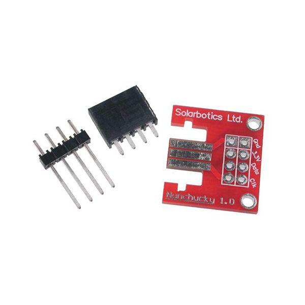 have them stacked and if you have extension cable or a dead controller cut and wire to the two then plug into CCM2. Edited 2020-07-22 07:39 by Quazee137 |
||||
| William Leue Guru Joined: 03/07/2020 Location: United StatesPosts: 411 |
Thanks for the reply on the I2C lines. I notice, however, that the Nunchuk plugs have what appears to be 5 traces: 3 on the top, 2 on the bottom. So that leaves 4 once we account for the I2C data line. I wonder what the other 4 are and whether those are also available on the back connector? -Bill Leue |
||||
mclout999 Guru Joined: 05/07/2020 Location: United StatesPosts: 509 |
I think we need a clear pin out to cable pins to GPIO set up. I also want to make sure to add any resistors that need to be added in line if they are needed. I have puchased some WII extition cables and plan to cut off the female and attacht them to a 40 pin IDE cable so you can only plug it in one way and you do not damage the NUMCHUCKS or Clasic controlers or the CMM2. I just really need a pin for pin diagram to make the cable and can anyone tell me if you need any other components in line. They call me Shai-Hulud (The maker) |
||||
| William Leue Guru Joined: 03/07/2020 Location: United StatesPosts: 411 |
Great plan! Please remember to post your solution when you find it! -Bill Leue |
||||
| Quazee137 Guru Joined: 07/08/2016 Location: United StatesPosts: 603 |
I did have a look here two nunchuk adapter Even four and eight port adapters can be made with the same chip familey. I think the best part is the base nunchuk code should work for the other nunchuks just need to point to the one being read. |
||||
| berighteous Senior Member Joined: 18/07/2020 Location: United StatesPosts: 110 |
So the questions remaining are: 1) who's going to build the adapter? and 2( where do we throw our money to get it? Edited 2020-07-26 11:19 by berighteous |
||||
| mkopack73 Senior Member Joined: 03/07/2020 Location: United StatesPosts: 261 |
OOh, interesting.. But I think we also want it to support the Wii Classic Controllers and it sounds like that one only handles the Nunchucks (based on the number of buttons and axis they're talking about). It's the same connector but likely some additional circuitry... That said, if somebody were to make such a thing I'd likely buy one! Edited 2020-07-26 11:20 by mkopack73 |
||||
TassyJim Guru Joined: 07/08/2011 Location: AustraliaPosts: 6538 |
Out of the box, the CMM2 can talk to 3 nunchuk/classic devices. There is no provision for having more than one on each I2C line so I think the multi-port adapters will take some effort to use. Each nunchuk requires 4 lines GND, 3.3V CLK and DATA. If you are using the I2C 1 or 2 ports on the rear connector, you will need 10k resistors form CLK and DATA to 3.3V. I am in the process of assembling an Arduino based adapter to make joysticks appear as Wii Classic to the CMM2. Due to the huge range of joysticks out there, I am only going to make it suit the ones I have but it is easy to alter the code to suit. Having everything appear as a Wii Classic to the CMM2 makes using them in software easy to do. I am hoping to do the same for PS2 mice but there is a shortage of available timeslots to do the bitbashing. Arduino Nanos are cheap, reliable, readily available, easy to program, cheap. Jim VK7JH MMedit |
||||
| mclout999 Guru Joined: 05/07/2020 Location: United StatesPosts: 509 |
Maybe if I restate it again clearly. I just want a pin to pin diagram to wire up the two other fmale WII ports directly available on the GPIO connector on the back. All we need for 3 numb chucks or Classic controllers is the three female ports to plug them into(the one on the front and the two on the GPIO pins. OR AM I WRONG? The manual says there is provision to use three but I can not find a simple wireing diagram to connect a 40 pin cable to 2 ADITIONAL female port or tells if you need resistors on any of those link-ups? We don't need any additional programable chips if we use Numbchucks and clasic controllers(or in the case of my custom fighting stick,the guts and cable of a 3rd party crap contorler) and we also get an already provide standard way to use controller input in our games. Once again or am I worng. Can anyone please clarify this for me or point me to a helpful resource? the manual just says you can use 3. Maybe the manual should have a very simple diagram showing how to connect those 2 WII ports to the GPIO connector. I do not want to fry my new CMM2(when it gits here) or my controllers. I Think the manual says that if you plug in a Numchuck upside down in the front port it might damage the controller or the CMM2(if yours comes in a full case you will neve see the legeons and warning on the PCB). I plan to glue a restrictor tab in that port hole in the cutout made by the manufacture if mine did not have the foresight to key the hole to prevent upside down insertions. I advise that you check yours and do the same. It only takes a moment's inattention to fry you equipment. Nintendo is great at idiot-proofing their equipment and we should take advantage of their inbuilt protections. The WII connectors are keyed for the protection of the devices but if your ports do not have the restrictor tab you can easly insert it upside down. My choice to use extentions cable female connectors will provide the keying as well for the two on the back. I intend to use a full 40pin IDE cable so it's locking pin will extend the idiot-proofing to that connection as well. These simple things are there to protect us from simple mistakes that can cause a lot of damage. Thanks for any help you can give me on the wiring diagram. They call me Shai-Hulud (The maker) |
||||
| TassyJim Guru Joined: 07/08/2011 Location: AustraliaPosts: 6538 |
Page 10 of the CMM2 manual has the pinout for the 40 way connector. To use a nunchuk on I2C 1 you : connect pin 3 (I2C SDA) to the DATA pin on the nunchuk connect pin 5 (I2C CLK) to the CLOCK pin on the nunchuk connect pin 1 (or any other 3.3V) to the VCC on the nunchuk connect pin 9 (or any other GND) to the GND on the nunchuk Also connect a 10k ohm resistor from pin 3 to 3.3V and connect a 10k ohm resistor from pin 5 to 3.3V To use a nunchuk on I2C 2 you: connect pin 27 (I2C2 SDA) to the DATA pin on the nunchuk connect pin 28 (I2C2 CLK) to the CLOCK pin on the nunchuk connect pin 1 (or any other 3.3V) to the VCC on the nunchuk connect pin 9 (or any other GND) to the GND on the nunchuk Also connect a 10k ohm resistor from pin 27 to 3.3V and connect a 10k ohm resistor from pin 28 to 3.3V VK7JH MMedit |
||||
| matherp Guru Joined: 11/12/2012 Location: United KingdomPosts: 11512 |
Minor correction to Jim's post. The 10K pullups are already built into the motherboard or mainboard designs so no extra resistors needed |
||||
| Quazee137 Guru Joined: 07/08/2016 Location: United StatesPosts: 603 |
here ya go 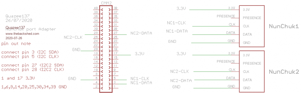 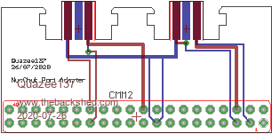 |
||||
| robert.rozee Guru Joined: 31/12/2012 Location: New ZealandPosts: 2528 |
these may be of interest: https://www.ebay.com/itm/283658623641 and https://www.aliexpress.com/item/32732747817.html (nunchuk sockets) cheers, rob :-) |
||||
| lizby Guru Joined: 17/05/2016 Location: United StatesPosts: 3784 |
How do those work with only 3 pins, or does the body and its legs provide 0V? PicoMite, Armmite F4, SensorKits, MMBasic Hardware, Games, etc. on FOTS |
||||
CircuitGizmos Guru Joined: 08/09/2011 Location: United StatesPosts: 1427 |
They have 6 pins. Micromites and Maximites! - Beginning Maximite |
||||
| capsikin Guru Joined: 30/06/2020 Location: AustraliaPosts: 342 |
Yeah, I thought that sort of thing must exist but had never seen them for sale. It's very hard to search for. I wonder why they are called "For WII Right Controller Socket Link W/ Left Controller Interface". What's this left and right stuff about? I think I see the 2 sets of three pins, but the back three are harder to see - reflecting the black plastic maybe |
||||
| lizby Guru Joined: 17/05/2016 Location: United StatesPosts: 3784 |
Ah, now I can see. The angles of the photos don't distinguish the separate rows very well. 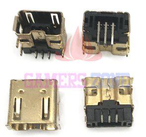 PicoMite, Armmite F4, SensorKits, MMBasic Hardware, Games, etc. on FOTS |
||||
| mclout999 Guru Joined: 05/07/2020 Location: United StatesPosts: 509 |
Thank you very much I will get to making an addaptor when I get the WII extention cales I ordered. They call me Shai-Hulud (The maker) |
||||
| Page 1 of 2 |
|||||
| The Back Shed's forum code is written, and hosted, in Australia. | © JAQ Software 2026 |
