
|
|
Forum Index : Microcontroller and PC projects : CCM2 Port Explorer
| Author | Message | ||||
Quazee137 Guru Joined: 07/08/2016 Location: United StatesPosts: 603 |
Got the boards in and here is a look. 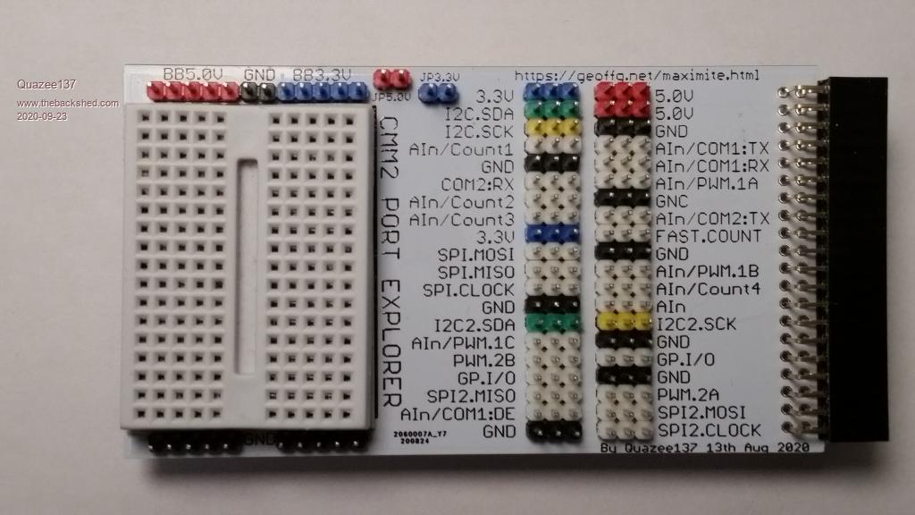 and a work sheet 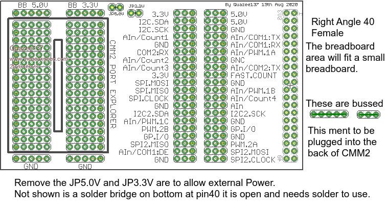 Let me know if there is any interest in this. I have ten boards, colour pin set and RA 40 pin. This is a spinoff of the MM170 Port Explorer I did for a group of kids. It will need something to hold it up to match the level of the CCM2 40 pin. Could try one of those pink erasers under the breadboard area.  I didn't find more than six colours of the pins or I would have done the SPI's too.  Have in FUN Quazee137 |
||||
| Womble Senior Member Joined: 09/07/2020 Location: United KingdomPosts: 267 |
Nice work there.  But which pis are "bussed"? not clear from your diagram. I assume its the two central banks of 3pins per i/o connection? I'll bet Nimue will be interested, except for the little problem of the Atlantic getting in the way. |
||||
mclout999 Guru Joined: 05/07/2020 Location: United StatesPosts: 509 |
Why did you go with a direct connect to the 40pin on CMM2 instead of a male 40 on the explorer like the RPI GPIO breakout boards? This looks like a great device. They call me Shai-Hulud (The maker) |
||||
| Quazee137 Guru Joined: 07/08/2016 Location: United StatesPosts: 603 |
Womble The groups of three pads from the 40 pin interface and groups five pads in the breadboard area. mclout999 I did the CCM2 Port Explorer like the MM170 version where it can be checked by a teacher/peers to make sure the wiring is good before plugging it in and powering up the CCM2. The 40 pin on the CCM2 is male and this is to be plugged into it. Ease of use for kids learning to do software/hardware relationships. At last minute before ordering the boards. I added the two GND pins between the 5Volt and 3.3volt buss above the breadboard to make it easier using an external supply for the breadboard. To use the CMM2 power plug in the shorting blocks on the JP5.0V and JP3.3V jumpers but only if not connecting to external power. Edited 2020-09-23 11:09 by Quazee137 |
||||
| William Leue Guru Joined: 03/07/2020 Location: United StatesPosts: 411 |
Any idea what you would charge for a board completely assembled or as a kit with the various components? I would love to have one! -Bill |
||||
| Quazee137 Guru Joined: 07/08/2016 Location: United StatesPosts: 603 |
William Not yet been going through ton of test on my immune system before they start a new treatment. The boards and parts are cheaper than the shipping cost. 10 pcb's and shipping $24. The 40pin RA female connector I got from Adafruit and the coloured pins and small breadboard from amazon "it was faster" at the time.  PM me with your info so I can check shipping cost. Could be cheap and put PCB in a letter and probably get away with something like $5 to $7 for it. A kit of all the parts may be around $12 to $15 plus shipping have to find my invoices to know for sure not looking to make money just cover cost. |
||||
| lizby Guru Joined: 17/05/2016 Location: United StatesPosts: 3782 |
Nice looking. I'd like to have one or more (sent a PM). Good idea with the colored pins. I just ordered these: https://www.ebay.com/itm/174003075264 "You should get it by Dec 29"--so who knows when I'll see them. I'd like to get orange and green too, but couldn't find orange and cost with green pins seemed high (for what I found). (Found green on Aliexpress.) ~ Edited 2020-09-25 00:06 by lizby PicoMite, Armmite F4, SensorKits, MMBasic Hardware, Games, etc. on FOTS |
||||
| robert.rozee Guru Joined: 31/12/2012 Location: New ZealandPosts: 2528 |
nice bit of design what would be really cool would be if the board had silkscreening on BOTH sides, so that it could be assembled with all components on the opposite side to normal, and then sat on TOP of the CMM case with a short ribbon cable curling round to the 40-pin CMM2 I/O connector, and with the breadboard section at the front. and i could see many users in the above configuration wanting to replace the solderless breadboard you've specified with one of these ones: https://www.ebay.com/itm/261917558371 cheers, rob :-) |
||||
| Quazee137 Guru Joined: 07/08/2016 Location: United StatesPosts: 603 |
robert.rozee Rob these where made for classrooms that share the CCM2's. Having the students wire up their work and then have a Teacher or peer review before plugging into the CCM2 and powering it up. I have other designs in the works using these. 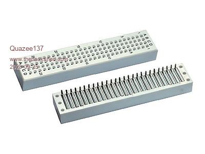 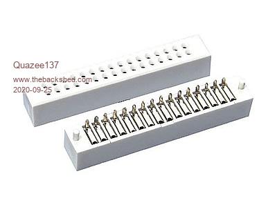 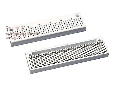 I can not get these in small amounts other than samples. They want me to order them in the 100's. The smaller breadboard was used as it fits the space and I think for most student projects it should do. I to like the bigger ones with power rails just too big for this version. Rob have a look at this. Scroll down near bottom. 40 pin IO I am mid project. When I get a few moments will make a flipped layout for those that want it. Edited 2020-09-25 22:34 by Quazee137 |
||||
CircuitGizmos Guru Joined: 08/09/2011 Location: United StatesPosts: 1427 |
Didn't know they made these. Where is your source? Micromites and Maximites! - Beginning Maximite |
||||
bigmik Guru Joined: 20/06/2011 Location: AustraliaPosts: 2981 |
Hi Quazee, All What he said.. I have never seen them before.. I bet they arent cheap though. Kind Regards Mick Mick's uMite Stuff can be found >>> HERE (Kindly hosted by Dontronics) <<< |
||||
| The Back Shed's forum code is written, and hosted, in Australia. | © JAQ Software 2026 |
