
|
|
Forum Index : Microcontroller and PC projects : CMM2:V5.05.06exp - Gui support with cursor callback to Basic
| Author | Message | ||||
| siwypiotr Senior Member Joined: 18/08/2020 Location: PolandPosts: 127 |
Of course, this was only sketch |
||||
| matherp Guru Joined: 11/12/2012 Location: United KingdomPosts: 10251 |
I think providing a location for a PDIP is a great approach  |
||||
| siwypiotr Senior Member Joined: 18/08/2020 Location: PolandPosts: 127 |
 Looks like Im done |
||||
| matherp Guru Joined: 11/12/2012 Location: United KingdomPosts: 10251 |
Suggest you connect to I2C2 (pins 27 and 28 on the 40-pin header) - I'll make this the default in the S/W |
||||
| siwypiotr Senior Member Joined: 18/08/2020 Location: PolandPosts: 127 |
This is how connected |
||||
| siwypiotr Senior Member Joined: 18/08/2020 Location: PolandPosts: 127 |
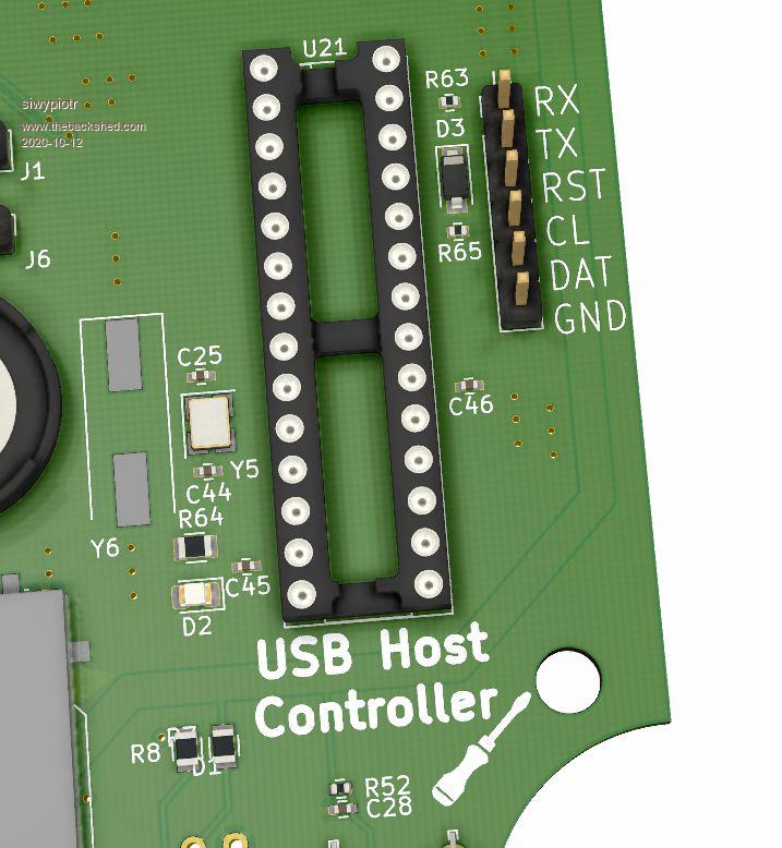
Revision B of my Maximite Delux is done: 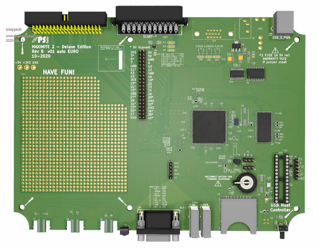 Here is schematic for the mouse controller from hobby electronic (just drop IC to the socket): 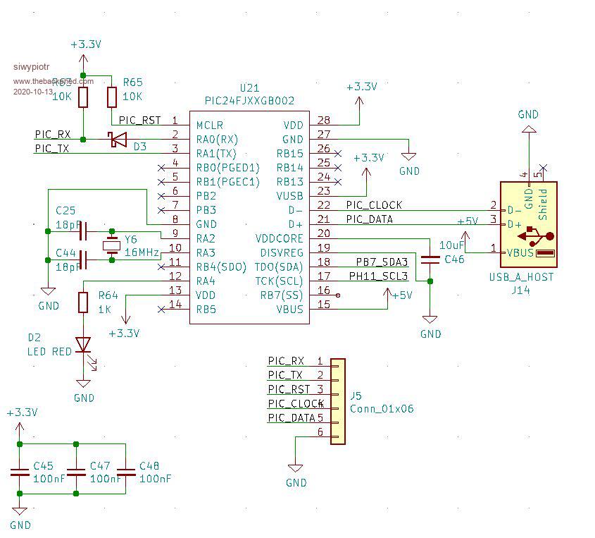 I will order PCBs + assembly tomorrow, please have a look if I did not missed anything. |
||||
| vegipete Guru Joined: 29/01/2013 Location: CanadaPosts: 1129 |
Could you add optional pull-up resistors on the PIC_CLOCK and PIC_DATA lines between U21 and J14? Pins 21 and 22 are 5V tolerant, so the pull-up can be to 5 volts. This would allow a suitably programmed U21 to talk to PS/2 mice also. (Pulling these 2 lines high puts a dual mode mouse into PS/2 mode.) Visit Vegipete's *Mite Library for cool programs. |
||||
| elk1984 Senior Member Joined: 11/07/2020 Location: United KingdomPosts: 228 |
Looks good. �I've seen some variations with a SCART socket, some with VGA. �Is that an option? �Which are you intending to ship as standard? I think I see an extra USB port on the front for the mouse. �Is the Joystick port a standard Atari D9 connection and pinout? Edited 2020-10-13 04:15 by elk1984 |
||||
| siwypiotr Senior Member Joined: 18/08/2020 Location: PolandPosts: 127 |
Yes there will be mouse support. DB9 pinout is standard for Atari joystick or SEGA gamepad. Pinout vs GPIO is as follows: DB9 FUNC -> GPIO 1 UP -> 35 2 DOWN ->36 3 LEFT -> 38 4 RIGHT -> 40 5 - 6 BUT A ->32 7 +5v 8 GND 9 BUT B ->33 Currently there is VGA. SCART is something I work on, everything is populated and requires only adding SCART plug. back panel is prepared to be easily cut to have the place for SCART: 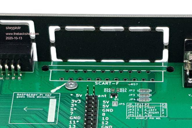 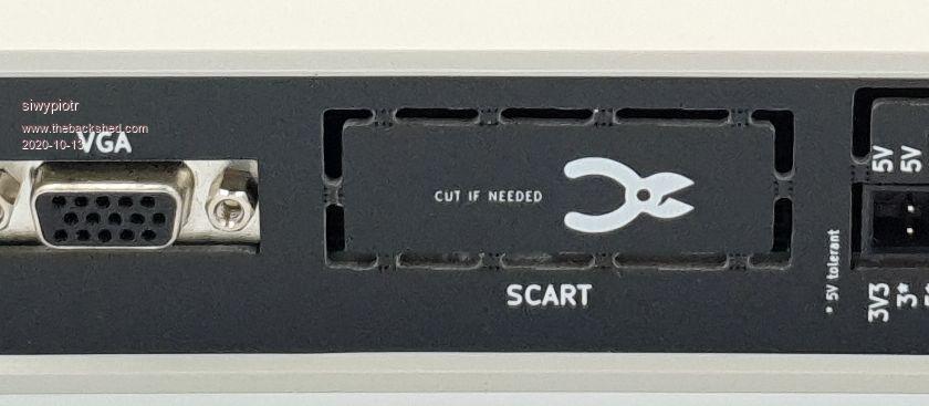 Unfortunately it does not work, there is image but no synchronization, maybe I failed somewhere on my schematic: 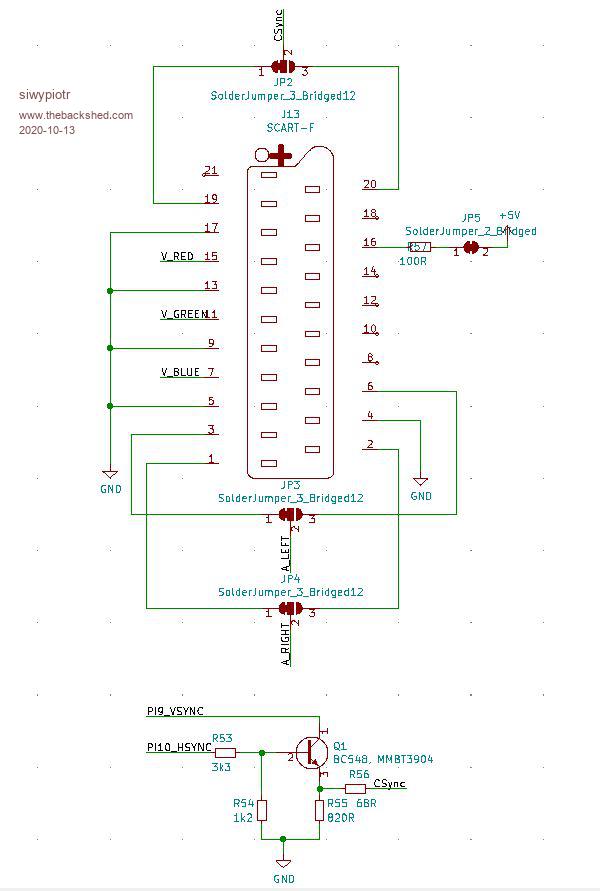 I need to work on it. The final goal is to have both VGA and SCART |
||||
| siwypiotr Senior Member Joined: 18/08/2020 Location: PolandPosts: 127 |
Sure no problem I can add pullup + solder jumper. How much 1K or 10K ? |
||||
| vegipete Guru Joined: 29/01/2013 Location: CanadaPosts: 1129 |
2.2K seems to work well. Holes for 4 header pins, similar to RUN/PROG, if possible, so that jumpers can be added or removed as required. (No need to populate the header pins though.) Visit Vegipete's *Mite Library for cool programs. |
||||
| siwypiotr Senior Member Joined: 18/08/2020 Location: PolandPosts: 127 |
Ok added: 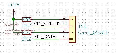  |
||||
| MauroXavier Guru Joined: 06/03/2016 Location: BrazilPosts: 303 |
Why in your board has described "DISCONNECT BATTERY FOR FIRMWARE FLASHING"? My board is a V1.4 with waveshare, and I use only the UPDATE FIRMWARE command and a USB-USB adapter, and I don't remove the battery. Does your circuit have some difference that needs this? |
||||
| siwypiotr Senior Member Joined: 18/08/2020 Location: PolandPosts: 127 |
You can flash it with battery, my board also flashes correctly with battery. But reality is that You should remove the battery to make sure that parameters are cleared. So far I never removed battery for flashing but at some point this can be issue when uploading new software. |
||||
| mclout999 Guru Joined: 05/07/2020 Location: United StatesPosts: 489 |
You can use "OPTION RESET" to reset all defaults. |
||||
| siwypiotr Senior Member Joined: 18/08/2020 Location: PolandPosts: 127 |
What if the new firmware expects something from memory area where old parameters are still stored and expects something different what is there? Can it crash? Can You still issue commands? What is easier: 1. Put a label about battery 2. Answer angry customers when new firmware crashes on boot somewhere in the future ? |
||||
| mclout999 Guru Joined: 05/07/2020 Location: United StatesPosts: 489 |
If it crashes after a upgrade THEN you pull the battery! OR Better you just bridge the pins 40 and 39 that also just resets everything to factory defaults(Manual Page 8). that way you still have no need to open the case. These guys have thought about almost everything. |
||||
TassyJim Guru Joined: 07/08/2011 Location: AustraliaPosts: 6270 |
OPTION RESET Reset all saved options to their default values. Easier than removing the battery and only needed when there has been a change to the layout of the saved options. When this occurs, the firmware instructions will advise to use OPTION RESET Battery removal is only required if for some reason, the "ground pin 40 on boot" reset procedure fails. Jim VK7JH MMedit |
||||
| siwypiotr Senior Member Joined: 18/08/2020 Location: PolandPosts: 127 |
Dear Maximite users New version of Maximite 2 have arrived. USB mouse host controller dip socket is added as well as additional USB port for connecting mouse. Chip can be bought separately from: https://www.hobbytronics.co.uk/usb-host-dip Functionality however is not tested (my hobby chip have not arrived) however I do not see any problem for it to work. 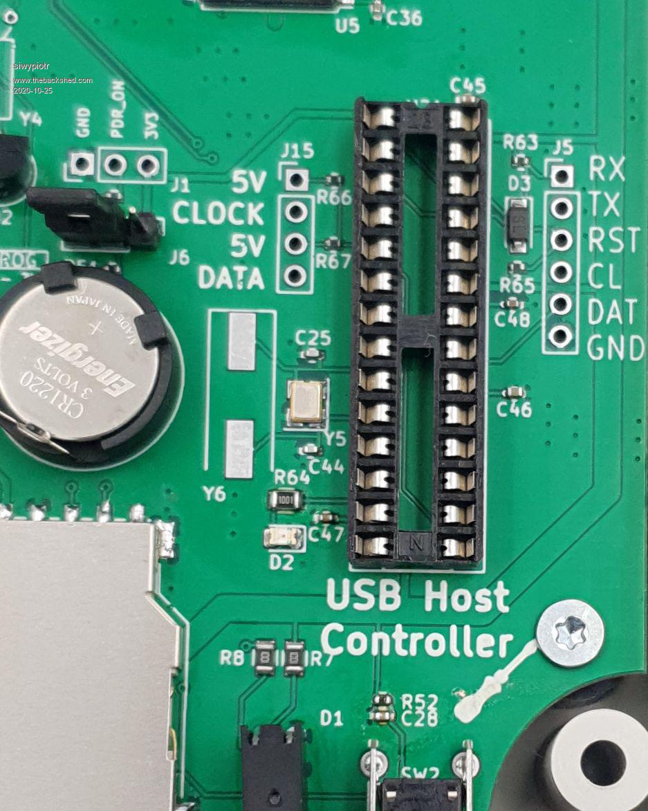 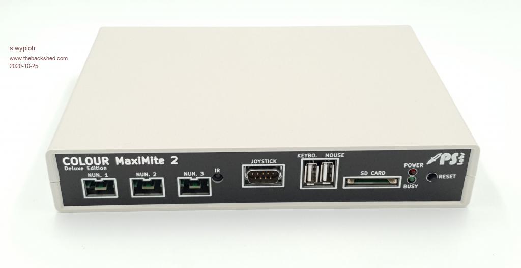 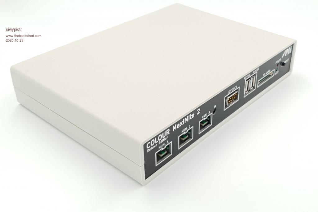 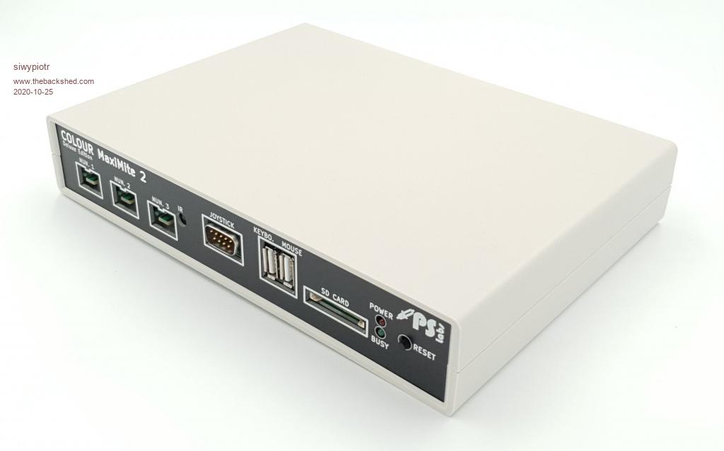 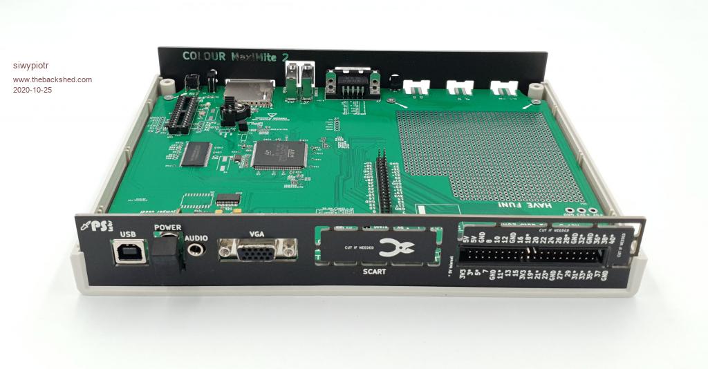 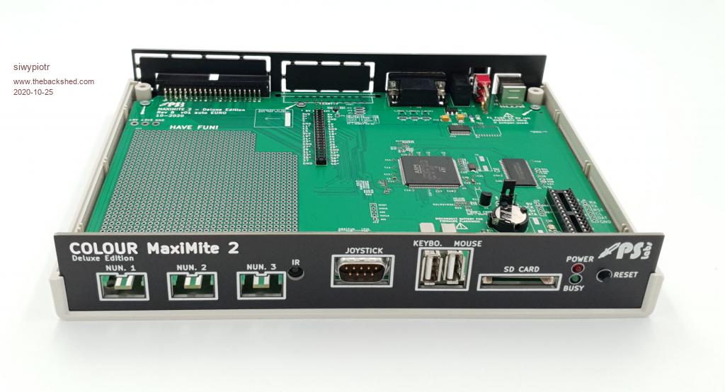 There are still couple units left if You are interested in purchase. |
||||
| siwypiotr Senior Member Joined: 18/08/2020 Location: PolandPosts: 127 |
USB version of Maximite is working! Latest version USB controller installation: https://youtu.be/lRGXsFi5QTs Latest version USB mouse functionality presentation: https://youtu.be/Tf0sAGK0CPM More information available on this thread: https://www.thebackshed.com/forum/ViewTopic.php?FID=16&TID=13005 |
||||
| The Back Shed's forum code is written, and hosted, in Australia. | © JAQ Software 2025 |
