
|
|
Forum Index : Electronics : 3 phase inverter for AC induction and servo motors
| Author | Message | ||||
| Warpspeed Guru Joined: 09/08/2007 Location: AustraliaPosts: 4406 |
That sounds like the most practical solution, and it offers excellent redundancy if a problem should arise. Cheers, �Tony. |
||||
Revlac Guru Joined: 31/12/2016 Location: AustraliaPosts: 1153 |
I would agree, nothing wrong with having more than one inverter, have been running 2 for some time, one runs the house the other runs some of the power points on one side of the house and any other large loads thrown at it with out affecting or worry about the load on the house inverter, some power can be switched from one to the other via a change over switch, one way only. There are a few inverters available that can be paralleled up to 9 units or so. With three phase there can be a few options depending on what you need, 3 singles or whatever, even some 3phase generators can be rewired to single phase without much trouble......wonder if that could be done with a 3phase inverter. Cheers Aaron Off The Grid |
||||
| Warpspeed Guru Joined: 09/08/2007 Location: AustraliaPosts: 4406 |
I suppose just a single phase inverter would be all that is needed, but with the facility to phase lock 120 degrees out of phase with an external reference input, or free run all by itself. Cheers, �Tony. |
||||
Haxby Guru Joined: 07/07/2008 Location: AustraliaPosts: 423 |
Poida, What are your thoughts on adding software programmable dead time into your mega code, and having 6 separate pin outputs go to the 6 individual Mosfet/IGBT drivers? The obvious problem is that it could be easy for a software error to turn on both high and low side drivers, which would really let out the smoke. But what is the genuine risk of something like that actually happening? If the mosfet driver logic is not inverted, all mosfets are off on startup, so I can't see any immediate problem. |
||||
| poida Guru Joined: 02/02/2017 Location: AustraliaPosts: 1432 |
the Mega can't do deadtime. It can make the 3 simple PWM outputs that is then sent into IR2184 type ICs to create the two outputs with deadtime for each half bridge. The Arduino Due can do deadtime and produce 3 PWM with complimentary outputs but it's a bit of an obsolete thing now. I still like them tho. The other choice seems to me to be STM32 Lately I have been wasting time playing with STM32F407 micros such as this but I paid only $10 years ago and I have 3 phase output with complimentary PWM and deadtime working now. I spent a day trying to get a Blue pill board (using the STM32F103) to do the same but even though the code is the same and STM manuals say they have the same TIMER1 hardware, it does not do deadtime, just the complimentary outputs for each of the 3 channels I need. These are also rather too old and now the smart kids are on to STM32F411 Black pill boards.these and they are cheap as chips. I will get a couple of them and see what they can do. wronger than a phone book full of wrong phone numbers |
||||
| poida Guru Joined: 02/02/2017 Location: AustraliaPosts: 1432 |
anyway, the previous post was dribbling on about micros that do the proper 6 outputs. I have confidence that I could program something like a STM32F4xx micro to produce 3 phase complimentary outputs with deadtime features of this would include: variable deadtime no outputs until the firmware boots and completes initialisation complete control over output amplitude and frequency (a VFD drive is easy to do!) no uncontrolled outputs at any time, including low level start up or brown outs I am close to starting making a power board for 3 phase 240V AC experiments. It will use optocouplers for gate drive and isolated dc-dc converters for the 3 high side gate drives. No gate drive ICs needed since the signalling will be the 6 signals of the 3 phase/comp output + DT from the STm32F4 firmware will have either single AC voltage feedback or individual AC phase feedback. one or the other to be enabled via jumper or user config. What I like about using the IR2184 chips is that the gate drive outputs can be disabled by default via a pull down resistor. This pin is driven high by firmware to enable output. The Arduino Nano and Mega can have digital output pins configured so that their outputs are ALWAYS LOW from no power/during boot/running code stages. This means a pin will be LOW until and only until the code is active, booted and intialised and then drive it high. This pin would be taken to the IR2184 shutdown pin. This is how I do it with the nanoverter and the picoverter. cross conduction is prevented thanks to the IR2184 logic and tight control of it's shutdown pin levels The more I think about it, the cost of 3 IR2184 plus 3x 10uF caps and 3x diodes for the 3 charh pumps is way cheaper and easier than having 6 optos + 3 dc-dc converters and needing the 6 pwm outputs with pwm and guaranteed deadtime and no uncordinated outputs during boot/brownouts wronger than a phone book full of wrong phone numbers |
||||
| Haxby Guru Joined: 07/07/2008 Location: AustraliaPosts: 423 |
Good stuff Poida. I've designed a 3 phase 200v IGBT board at my end. I have sent the design away and I'm just waiting for it to be manufactured. I can send you one if it will help you out? It uses UCC5350M gate drivers and is supposed to work with the EG8030 carrier board. It uses my favourite Hi-Link 3w power supplies for gate drive power supply. |
||||
| Haxby Guru Joined: 07/07/2008 Location: AustraliaPosts: 423 |
My boards came in. Yay. But I'm waiting for the EG8030 on the egs031 carrier board before I can test it. Might still be a month away. Boo. My board uses 6x ucc5350m drivers. Very fast (not opto based) 6amp isolated drivers with Miller clamp built in. I have high hopes for them not to cause trouble at 200 to 300v DC. IGBTs chosen were ikw75n60. 75A at 100c. Hoping will be good for 3 or more killer-wasps at 200v per phase. So 10-12kw or more inverter with only 6 IGBTs. We'll see. The EGS031 carrier board uses eg3012 MOSFET drivers, which are only good for 100v max. So I'll remove the driver chips and wire the logic straight through to the original pinout. This logic signal then goes directly to one of 6 IGBT drivers. You can see each of the 6 identical drivers in the pic below. Each driver section has a good old Hi-Link 15v independent power supply, Mounted on the back of the board. A further single 5v Hi-Link power supply powers the egs board and the LV side of the isolated drivers. I'm thinking of drawing up a carrier board that houses a mega mini 2560 running Poidas 3 phase code, with dead time chips onboard so that the pinout is interchangeable with the EGS031. There was a good discussion under the topic of "dead time insertion" on this awesome forum. This would break away from the unknown vagueness of the EG8030 (non existent English) manual. Anyway if anyone wants to tinker with 3 phase inverters or speed controllers, PM me and I'll send you a board at cost, or could send you the board file. 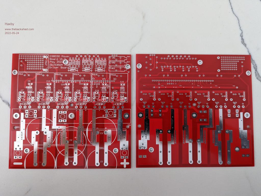 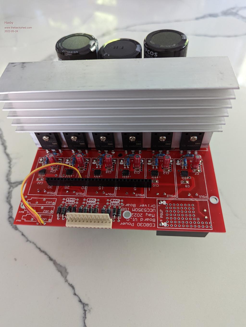 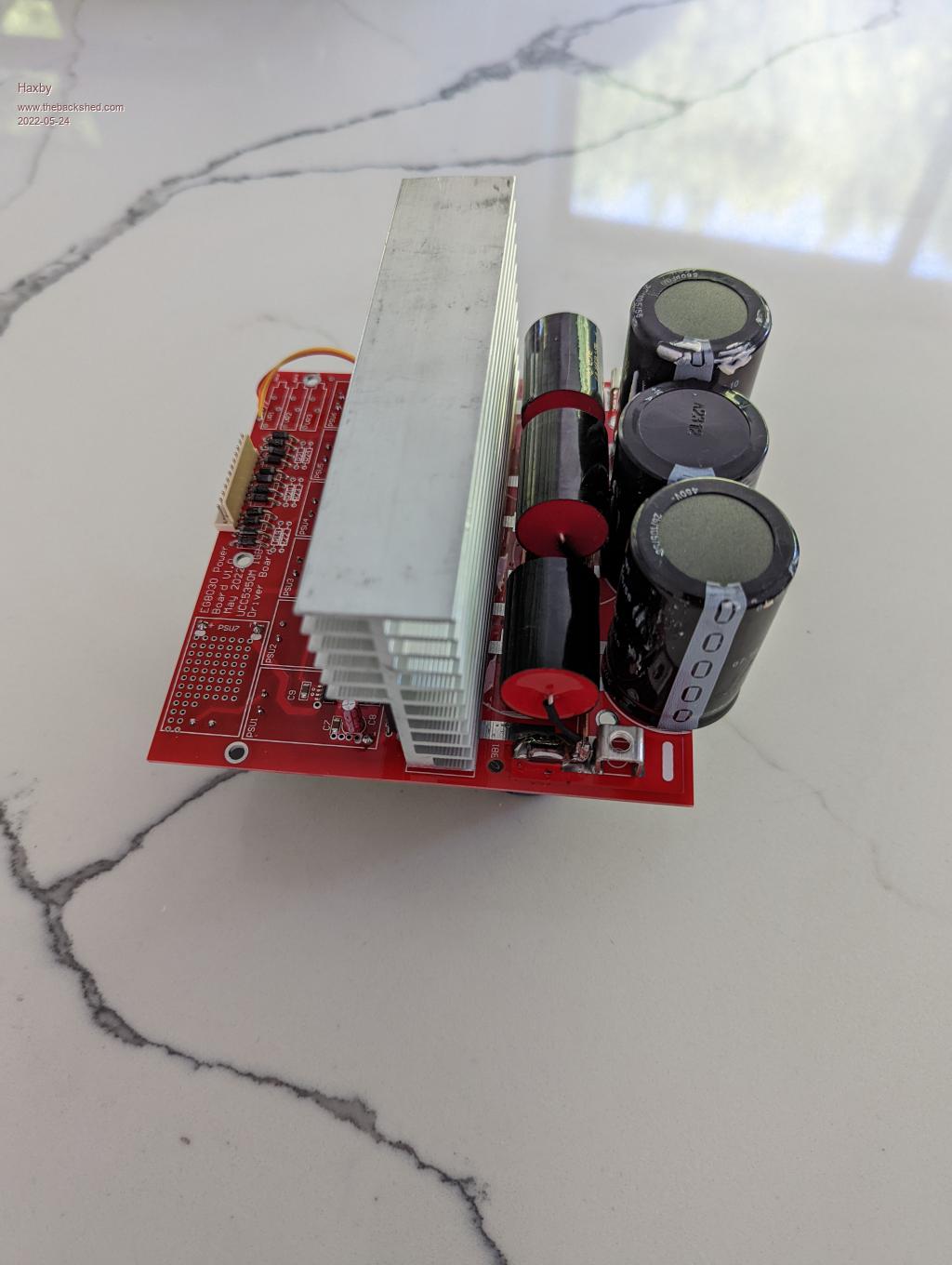 |
||||
| Revlac Guru Joined: 31/12/2016 Location: AustraliaPosts: 1153 |
Boards are looking great Haxby, and should make very useful size inverter, well done.  I Might have some questions at a later stage. Cheers Aaron Off The Grid |
||||
| rogerdw Guru Joined: 22/10/2019 Location: AustraliaPosts: 904 |
Agreed, they look awesome Haxby. Can't wait to see the completed project. And great idea hiding the converters under the board. What sort of transformer/s will you be using. Cheers, Roger |
||||
| poida Guru Joined: 02/02/2017 Location: AustraliaPosts: 1432 |
The board looks interesting for the experiments I want to do. Could you send me one? please PM me the paypal info.. all 6 gate drive signals are isolated That is perfect for me. Already I have great looking waveforms out of the STM32F407 board with 3 phase SPWM with complimentary outputs & programmable deadtime. It is possible to do the same with the Arduino Due. PWM output is tightly controlled out of power up so no blowups are expected. This is confirmed from oscilloscope recording of the pwm outputs The power board is one thing. Me making 3 toroids and 3 more chokes is another. And finding suitable 3 phase AC test loads. I do have a 1/2 HP 3ph motor but something bigger might be nice - and not reactive load either. 3 toasters hooked up delta and or star? an idea of how little code is needed to get the STM32F4 going. I have tried using the "Blue Pill" STM32F103 I got 3 phase with comp outputs but no dead time. Maybe it's a fake chip. dunno this configures timer1 for 3 phase pwm with comp. output and deadtime not a lot of code void Timer1_Configuration(void) { // // timer1, ch1,2,3 OC and OCN outputs enabled with deadtime // correct signaling for 3 phase inverter // uint16_t ccmr1=0, ccmr2=0, �ccer=0; TIM1->BDTR = 0x0c50; // DT part is low 8 bits TIM1->PSC = 0; TIM1->ARR = 8400; TIM1->CR1 = 0; TIM1->RCR = 0; ccmr1 = 0x6868; // ch1,2 TIM_OCPreload_Enable & PWM mode 1 ccmr2 = 0x0068; ccer = 0x0555; // ch1,2,3 OC and OCN config � OC enabled, active high, OCN enabled, active high TIM1->CCER = ccer; TIM1->CCMR1 = ccmr1; TIM1->CCMR2 = ccmr2; TIM1->CCR1 = 100; // ch1 pwm width for boot up TIM1->CCR2 = 100; // 100 clocks wide of 8400 clock TIM1->CCR3 = 100; // cycle is not much power TIM1->CR2 = 0; TIM1->CR1 |= 0x0080; // enable preload TIM1->BDTR |= 0x8000; // enable PWM outputs, needed for timer1 TIM1->CR1 |= 0x0001; // enable timer } and this is the interrupt code, called at 20kHz where the sinewave pwm width values are updated for each of the 3 phases void TIM1_UP_TIM10_IRQHandler(void) { unsigned int j,k; if (TIM_GetITStatus(TIM1, TIM_IT_Update) != RESET) { TIM_ClearITPendingBit(TIM1, TIM_IT_Update); pa++; if (pa > 399) { pa=0; GPIO_SetBits(GPIOD, GPIO_Pin_12); } j = pa + 133; if (j > 399) j = j - 400; k = pa + 266; if (k > 399) k = k - 400; //GPIO_SetBits(GPIOD, GPIO_Pin_12); TIM1->CCR1 = (spwm[pa] * pwr) >> 8; TIM1->CCR2 = (spwm[j] * pwr) >> 8; TIM1->CCR3 = (spwm[k] * pwr) >> 8; .... } Edited 2022-05-25 09:28 by poida wronger than a phone book full of wrong phone numbers |
||||
| Haxby Guru Joined: 07/07/2008 Location: AustraliaPosts: 423 |
Thanks for the encouragement. Another purpose for the board is to be able to run those 3 phase IGBT modules commonly found in air conditioning and motor inverters. Those Mitsubishi modules typically have 6 IGBTs in a nice single package, and to drive them they need independent 15v supplies and independent gate drives. I have a couple of 150A modules from old motor controllers to play with. So instead of mounting the MOSFETs on the board, I could run some shielded gate drive wires to the module. What transformers? Well I'm thinking that the source will be a mixture of direct solar and my 180 to 210v Prius battery. So the transformers will have to suit these voltages. 3 X aerosharp 92v:230v transformers, with a few extra windings on the 92v side, is my first guess. Since that wouldn't be much work for a test setup, though that would be only 1.5kw continuous per phase. This is where I get lost with the maths, and star vs delta wiring confuses me. I'm pretty sure this is right but Please correct me if I'm wrong on the following: Delta should be chosen on the primary side so that regulation is well maintained. Star should be chosen on the output side so that there is a neutral point. I think the primary winding voltage rating should be calculated as input DC voltage divided by 1.41. Much like a single phase system. So 180v/1.41= 127.65 The turns on the aerosharp are about 1v per turn, so about 40 extra turns on the 92v side will get me there. |
||||
| poida Guru Joined: 02/02/2017 Location: AustraliaPosts: 1432 |
I think I will go delta on the primaries and star on the secondary This gives a neutral and 3 phases I use the neutral for getting Vfb. Connect netral and phase 1 to 240V->12V transformer for ph1 Vfb, etc.. I have a look at the Arduino Due again since it can do separate dead time for the start and end of a pwm pulse. This might be important in this design with IGBT and isolated drivers on both low and high side giving difficult to calculate gate rise times. And the rise times could well be different, potentially setting up shoot through. below is a DSO capture showing 1us dead time on the left and 4us on the right. The Yellow could be the low side drive signal The Light Blue being the high side signal. 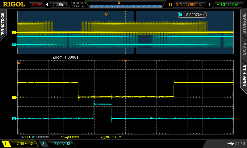 The dead time is able to be set in increments of system clock which is 84MHz, and can go all the way to 100% of the 20kHz PWM No need for all that though, we have plenty of control here. wronger than a phone book full of wrong phone numbers |
||||
| Haxby Guru Joined: 07/07/2008 Location: AustraliaPosts: 423 |
Poida I sent you an email to @bqd... |
||||
| poida Guru Joined: 02/02/2017 Location: AustraliaPosts: 1432 |
It's trival to make a VFD with this. V/F = constant so that means the output voltage is multiplied by the frequency and let's start with 240V AC at 50Hz. Get the desired frequency from the potentiometer then modify PWM modulation by the fraction (pot. freq) / 50 e.g. if set at 10 Hz, then output voltage AT 10 Hz will be 240V * 10/50 or 48V AC This project is looking to be fun wronger than a phone book full of wrong phone numbers |
||||
| Haxby Guru Joined: 07/07/2008 Location: AustraliaPosts: 423 |
I don't think you will need any transformers for a VFD if input voltage is high enough. You might not need much of a choke either. Maybe just a capacitor on each output. |
||||
| Haxby Guru Joined: 07/07/2008 Location: AustraliaPosts: 423 |
I'd just have a LEM current sensor on 2 of the 3 outputs to monitor things and shut down on over current |
||||
| poida Guru Joined: 02/02/2017 Location: AustraliaPosts: 1432 |
3 phase inverter code for the Due set the 3 Vfb = 2.47V DC at your required AC output and connect them to A0,A1,A2 PWM signals are phase 1 (low side) 35, (high side) 34 phase 2 �(low) 37, �(high) 36 phase 3 �(low) 39, (high) 38 it's got the soft start and stop, runs at 50Hz with 20kHz PWM Control on/off via pin D8 1uS dead time, same for start and end of the pulse volatile uint16_t spwm[400],pa1, pa2,pa3,uf,oen,init_done; volatile float pwr[3], ac_output[3]; volatile uint16_t ipwr[3],dt; volatile uint32_t pd; volatile int sst; float Input[3], Output[3], Setpoint[3]; float errSum[3], lastErr[3], kp, ki, kd; void check_switch_cont(void); void do_pid(int); void init_vars(void); void pwmc_setup(void); void do_pid(int i) { � � float error, dErr, timeChange = 0.01; � � � error = Setpoint[i] - Input[i]; � errSum[i] += (error * timeChange); � dErr = (error - lastErr[i]) / timeChange; � Output[i] = kp * error + ki * errSum[i] + kd * dErr; � lastErr[i] = error; } void init_vars() �{ �kp = 0.1; � � // set up PID for AC output voltage control �ki = 0.0; �kd = 0.01; �errSum[0] = errSum[1] = errSum[2] = 0.0; � � � �lastErr[0] = lastErr[1] = lastErr[2] = 0.0; �Setpoint[0] = Setpoint[1] = Setpoint[2] = 0.75; �sst = 0; �pwr[0] = pwr[1] = pwr[2] = 0.0; �ipwr[0] = ipwr[1] = ipwr[2] = 0; �uf = 0; �ac_output[0] = ac_output[1] = ac_output[2] = 0.0; �} void setup() { � �int i; �float th,w; �init_vars(); � �init_done = 1; �// sin() table, offset +1 to keep it all positive, scale by 4200 being pwm clock period �for(i=0; i < 400; i++) � �{ � � �th = 2.0 * 3.14159 * (float)i / 399.0; � � �w = 4200.0 * 0.5 *(1.0 + sin(th)); � � �spwm[i]= (int)w; � �} �// init phase angles for 3 phases 0 to 399 possible positions (400 element sin() lookup table) � �pa1 = 0; �pa2 = 133; �pa3 = 266; �// dead time, in 84MhHz clocks, 1uS �dt = 84; �// pwm freq will be 20KHz �pd = 4200; �pwmc_setup(); �pinMode(8,INPUT_PULLUP); �pinMode(13,OUTPUT); } void check_switch_cont() { � �if (digitalRead(8) == 0) � � // pin D8 grounded � �{ � �if (init_done == 0 && sst == 0) � � �{ � � �init_vars(); � � �init_done = 1; � � �} � � �oen = 1; � � �// slow start � �digitalWrite(13,1); � �} else �{ � �oen = 0; � � � �if (sst > 0) � � �init_done = 0; � �digitalWrite(13,0); �} } void loop() { int i; for(i=0; i < 3; i++) �{ � �ac_output[i] = (float)analogRead(i) / 1024.0; � // maybe filter this? � �//ac_output[i] = 0.0; �} if (uf == 1) �{ � � �uf = 0; � �if (oen == 1) sst++; � � �// slow start. If output is enabled, keep starting up. sst = output pwm% or approx. voltage. � �if (sst > 251)sst = 251; �// stop increasing when sst has got to the end of slow start. when = 251, this enables PID. See below.. � �if (oen == 0) sst--; � � �// if stopping, slow stop � �if (sst <= 0) sst = 0; � � � � // once fully stopped, no more changes to sst needed � � � �if(sst > 0 && sst < 250) � � � // slow start timer counts to 250 with gentle ramp up, then switches over to PID control. � � � �{ � � � � � � � � � � � � �// sst can increase or decrease, giving the slow start and slow stop. � � � �for(i=0; i < 3; i++) � � � � � �{ � � � � � �if (oen == 1) � � � � � � �{ � � � � � � � �if(ac_output[i] < Setpoint[i]) � � � � � � � �pwr[i] += 1.0/250.0; � � // bang-bang control, should AC output reach setpoint prior to PID. � � � � � � �else � � � � � � � � � �// During slow start need to ensure output is tracking setpoint � � � � � � � �pwr[i] -= 1.0/250.0; � � // should output get close enough to matter. � � � � � � �} � � � � � �else � � � � � � �pwr[i] -= 1.0 /250.0; � � �// this will execute in slow stop � � � � � �} � � � �} � � � � �if (sst == 251) � � � // once sst = 251, run PID. the above bang-bang control will NOT have executed, because sst = 251 � � � �{ � � � �for(i=0; i < 3; i++) � � � � � � � � � � � � � � � � �{ � � � � � � � �Input[i] = ac_output[i]; � � � � � �do_pid(i); � � � � �pwr[i] = pwr[i] + Output[i]; � � � � �} � � � �} � �for(i=0; i < 3; i++) � � � � � � � � � � � � � � �{ � � � � � �if (pwr[i] > 0.99) pwr[i] = 0.99; � � // clamp. Do math in floating point to prevent any integer overflow � � �if (pwr[i] < 0.01) pwr[i] = 0.01; � � � � �ipwr[i] = (int)(256 * pwr[i]); � � � � � � � � �} �check_switch_cont(); � � �} } void pwmc_setup() { �//Configure PWM channels 0,1,2,3 (PWML0,PWMH0,PWML1,PWMH1,PWML2,PWMH2,PWML3,PWMH3), �// (port C.2,C.3,C.4,C.5,C.6,C.7,C.8,C.9), (pins P34,P35,P36,P37,P38,P39,P40,P41) �REG_PIOC_PDR = 0x3FC; �//B1111111100, PIO Disable Register �REG_PIOC_ABSR = REG_PIOC_ABSR | 0x3FCu; //B1111111100, Peripheral AB Select Register �pmc_enable_periph_clk(ID_PWM); � �REG_PWM_ENA = REG_PWM_SR | B1111; //PWM Enable Register | PWM Status Register (activate channels 0,1,2,3) �REG_PWM_CMR0 = 0x10000; //Channe0 Mode Register: Dead Time Enable DTE=1 �REG_PWM_CMR1 = 0x10000; //Channe1 Mode Register: Dead Time Enable DTE=1 �REG_PWM_CMR2 = 0x10000; //Channe2 Mode Register: Dead Time Enable DTE=1 �REG_PWM_DT0 = dt + (dt << 16); �REG_PWM_DT1 = dt + (dt << 16); �REG_PWM_DT2 = dt + (dt << 16); �REG_PWM_CPRD0 = 4200; //Channe0 Period Register �20 kHz �REG_PWM_CPRD1 = 4200; �REG_PWM_CPRD2 = 4200; �REG_PWM_CDTY0 = 100; �REG_PWM_CDTY1 = 100; �REG_PWM_CDTY2 = 100; �NVIC_DisableIRQ(PWM_IRQn); // set up interrupt �NVIC_ClearPendingIRQ(PWM_IRQn); �NVIC_SetPriority(PWM_IRQn, 0); �NVIC_EnableIRQ((IRQn_Type)36); //NVIC_EnableIRQ(PWM_IRQn); �PWM_INTERFACE->PWM_IER1 = 0x0003; //enable interrupt on channel 0 �PWM_INTERFACE->PWM_IDR1 = 0x00FF00fc; �PWM_INTERFACE->PWM_IER2 = 0x00000300; �PWM_INTERFACE->PWM_IDR2 = 0x0FFFcFFF; �REG_PIOD_PER = 0x00ff; �REG_PIOD_OER = 0x00ff; �REG_PIOD_OWER = 0xFFFF; } void PWM_Handler(void) // PWM interrupt handler { � long ir1, ir2; � ir1 = PWM_INTERFACE->PWM_ISR1; // clear interrupt flag � if ((ir1 & 1) == 1) � � �{ � � � �pa1++; � � � �if (pa1 == 200) � � � � �uf = 1; � � � �if (pa1 > 399) � � � � �{ � � � � � �pa1 = 0; � � � � � �REG_PIOD_ODSR = 3; � � � � � �uf = 1; � � � � �} � � � �pa2++; � � � �if (pa2 > 399) � � � � �pa2 = 0; � � � �pa3++; � � � �if (pa3 > 399) � � � � �pa3 = 0; � � � � � �REG_PIOD_ODSR = 0; � � � � �REG_PWM_CDTY0 = (spwm[pa1] * ipwr[0]) >> 8; � � �} � if ((ir1 & 2) == 2) � � �{ � � � �REG_PWM_CDTY1 = (spwm[pa2] * ipwr[1]) >> 8; � � �} � if ((ir1 & 4) == 4) � � � �{ � � � �REG_PWM_CDTY2 = (spwm[pa3] * ipwr[2]) >> 8; � � � � � � �} } Edited 2022-05-27 12:44 by poida wronger than a phone book full of wrong phone numbers |
||||
| Haxby Guru Joined: 07/07/2008 Location: AustraliaPosts: 423 |
I have never thought of having separately programmable on and off time. That's an interesting feature. What are the ramifications of a very long dead time and vastly different on/off time? If I try to use the 3 phase IGBT modules that I have, I'd be inclined to start with a 1.5uS dead time and a low-ish 5khz frequency. |
||||
| rogerdw Guru Joined: 22/10/2019 Location: AustraliaPosts: 904 |
This subject is something I have no idea about Phil, but I did just read all about it here in some old threads. All I have to do is find it again ... which may be difficult. I did find this article really interesting, though not the one I was looking for. I had been wondering why many of the mosfet driving chips with 'totem pole' like drive transistors did not join their common point ... and were often just joined on the board. And then discovered that they were left seperate in case the designer wanted to have more control over turn on and turn off times. Cheers, Roger |
||||
| The Back Shed's forum code is written, and hosted, in Australia. | © JAQ Software 2025 |
