
|
|
Forum Index : Electronics : 3 phase inverter for AC induction and servo motors
| Author | Message | ||||
| InPhase Senior Member Joined: 15/12/2020 Location: United StatesPosts: 178 |
The longer the dead time, the higher the inductive "kickback" from the transformer. |
||||
Haxby Guru Joined: 07/07/2008 Location: AustraliaPosts: 418 |
Thanks gents. And what about the switching frequency? The modules I have say they will switch at 20khz maximum, so I reckon 5 to 10khz would be closer to their normal operating frequency, and that's what I'd aim for. I'm guessing that the lower the switching frequency you go, the worse the sine wave looks, but that would likely only be an issue close to the zero crossing, which is where the IGBTs will be on for a very very short time. The rest of the sine wave will have longer on time, no matter what switching frequency you choose. so that's just my theory. Am I getting that right? Sorry if these questions sound basic. |
||||
| poida Guru Joined: 02/02/2017 Location: AustraliaPosts: 1388 |
I will test at both 20kHz and 10kHz Looking at the rise and fall times of the IGBTs I think 20kHz will present no problems. But I am a hacker so its always "well that worked out well! no idea why.." Rain this next 5 days so It's On.. wronger than a phone book full of wrong phone numbers |
||||
| poida Guru Joined: 02/02/2017 Location: AustraliaPosts: 1388 |
further adventures in generating 3 phase PWM with complimentary outputs and deadtime have this code working with the "BlackPill" micro. This is a very cheap, small but capable micro. about $5.50 with shipping It has hardware floating point which makes it about 15x faster than the 32bit Arduino Due and a lot faster again than the Nano when doing floating point math. I like floating point hardware.. You use the Arduino IDE and load the boards for STM32 from STMicro select STM32F4, choose F401CC, program it with the serial cable in DFU mode This code is tiny but is the guts of 3 phase + comp outs + DT volatile int pa, sa[400][3]; HardwareTimer t1(TIM1); void t1_int(void) { if ((TIM1->SR & 0x0010) == 0x0010) { TIM1->SR =0; // reset int flag - mandatory or else it fires continuously pa++; //clock the phase angle counter if (pa >= 400) // done 360 degrees? { pa = 0; // then restart at 0 degrees GPIOC->ODR = 0x8000; GPIOC->ODR = 0x0000; //send a sync pulse for DSO } TIM1->CCR1 = sa[pa][0]; // phase 1 pwm width TIM1->CCR2 = sa[pa][1]; // phase 2 TIM1->CCR3 = sa[pa][2]; // phase 3 } } void setup() { int i; float th,p; // sine() lookup table, with the three phases different by 120 degrees for (i=0; i < 400; i++) { th = 2.0 * 3.14159 * (float)i / 400.0; p = (1.0 + sin(th)) * 2100; sa[i][0] = (int)p; th = 2.0 * 3.14159 * (float)(i + 133) / 400.0; // 399 entries in table = 360 degrees p = (1.0 + sin(th)) * 2100; // so +133 entries = 120 degrees sa[i][1] = (int)p; th = 2.0 * 3.14159 * (float)(i + 266) / 400.0; p = (1.0 + sin(th)) * 2100; sa[i][2] = (int)p; } pa = 0; // init phase angle = zero // TIMER1 configs PWM_pin_config(); Timer1_config(); t1.attachInterrupt(t1_int); HAL_NVIC_SetPriority(TIM1_UP_TIM10_IRQn ,1,3); TIM1->DIER = 0x0001; // let it rip, enable TIMER1 // PC13 LED setup and PC15 for 50Hz sync pulse pinMode(PC13,OUTPUT); pinMode(PC15,OUTPUT); } void loop() { // put the AC voltage control code here // not a lot to see, we've seen it before } void Timer1_config(void) { // // timer1, ch1,2,3 OC and OCN outputs enabled with deadtime // correct signaling for 3 phase inverter // uint16_t ccmr1=0, ccmr2=0, ccer=0; __HAL_RCC_TIM1_CLK_ENABLE(); TIM1->BDTR = 0x0c50; // DT part is low 8 bits TIM1->PSC = 0; TIM1->ARR = 4200; TIM1->CR1 = 0; TIM1->RCR = 0; // ch1,2 TIM_OCPreload_Enable & PWM mode 1 // ch1,2,3 OC and OCN config OC enabled, active high, OCN enabled, active high TIM1->CCER = 0x0555; TIM1->CCMR1 = 0x6868; TIM1->CCMR2 = 0x0068; TIM1->CCR1 = 1; // ch1 pwm width TIM1->CCR2 = 1; // ch2 pwm width TIM1->CCR3 = 1; // ch3 pwm width TIM1->CCR4 = 1; TIM1->CR2 = 0; TIM1->CR1 |= 0x0080; // enable preload TIM1->BDTR |= 0x8000; // enable PWM outputs, needed for timer1 TIM1->CR1 |= 0x0001; // enable timer } void PWM_pin_config(void) { // manual GPIO setup, the HAL functions do not work with TIMER1 ALT1 complimentary output pins // timer 1, ch 1,2,3 alt functions out A8,9,10 __HAL_RCC_GPIOA_CLK_ENABLE(); GPIOA->PUPDR = 0x00154000; // 10,9,8 pins pull up 01 GPIOA->OSPEEDR = 0x003fC000; // speed is 11 or fastest GPIOA->MODER = 0x002a8000; // Alt function GPIOA->OTYPER = 0; // output push-pull GPIOA->AFR[1] = 0x00000111; // AF = 0001 = AF1 // timer1 ch 1,2,3 complimentary outputs B13,14,15 __HAL_RCC_GPIOB_CLK_ENABLE(); GPIOB->PUPDR = 0x54000000; GPIOB->OSPEEDR = 0xfc000000; GPIOB->MODER = 0xa8000000; GPIOB->OTYPER = 0; GPIOB->AFR[1] = 0x11100000; } wronger than a phone book full of wrong phone numbers |
||||
| iannez Newbie Joined: 05/07/2019 Location: ItalyPosts: 23 |
Peter great job as always! I lost more an afternoon to understand why with timer1 it is necessary TIM1-> BDTR | = 0x8000; In other timers it is not necessary. Can you trust the precision of the Deadtime compared to the classics IR2110 or 2183? Cheers, Angelo |
||||
| poida Guru Joined: 02/02/2017 Location: AustraliaPosts: 1388 |
Hi Angelo for most timers it's not but for TIMER1 (only one with DT) TIM1-> BDTR | = 0x8000 is needed. on page 310 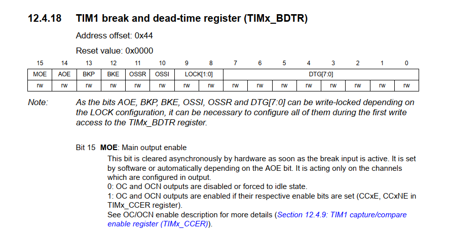 Precision of DT is very good. the 0x50 as used is 80 clocks delay of the 84MHz main clock We can resolve it to single clock counts and from what I've seen on the DSO it's invariant over time. wronger than a phone book full of wrong phone numbers |
||||
Revlac Guru Joined: 31/12/2016 Location: AustraliaPosts: 961 |
Nice work Peter, its a nice little board for that price, just thinking about the potential size of the 3Phase inverter, and that tiny board is the brains that run it, compare it to something that was built maybe 15 years or so ago.  Cheers Aaron Off The Grid |
||||
| Haxby Guru Joined: 07/07/2008 Location: AustraliaPosts: 418 |
Poida, if I was to design an Arduino clone brain board for my 3 phase power board, would you recommend I use the black pill as the basis? |
||||
| poida Guru Joined: 02/02/2017 Location: AustraliaPosts: 1388 |
for sure the black pill micro. 3.3V outputs so choose your gate drive IC input resistors carefully. Maybe they are voltage inputs, not current driven so it's all OK. The Arduino nano can only do one pair of complimentary outputs and those do not have dead time. So scrub that. The Arduino mega can do 3 channels of the same but no dead time. No good. Unless you choose to use IR's gate drive ICs that generate dead time or roll your own with caps, logic gate ICs and whatnot. The STM32F401 (black pill) can do 3 channels with dead time. I can give you the pinout for the PWM outputs and analog inputs. from 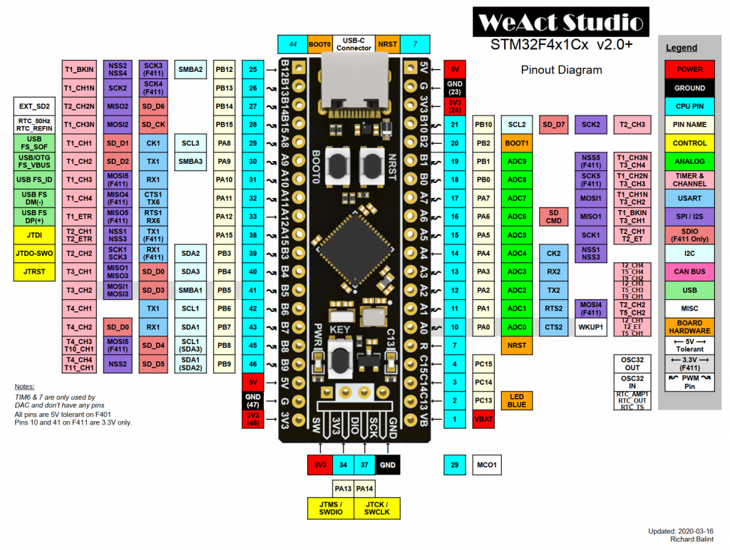 it's ch1 high side A8, lowside B13 ch2 high side A9, low B14 ch3 high side A10, low B15 Analog inputs are A0,A1, A2 for the 3 phase Vfb and maybe A3 for a AC output setting if needed, else just use trimpots on all 3 Vfb. All analog inputs need to be between 0 and 3.3V pin B9 could be inverter run/stop signal pin PC13 is connected to the on-bard LED so I use that to signal inverter is running. uploading the firmware needs a bit of software to be installed. Let's go there when needed. (STM cube programmer and arduino IDE plus STM's board definitions. It works fine on Windows 10) close examination of the above image shows pin B14 is "timer 2/channel 2" this is a mistake. It's timer 1/channel 2 which is what we need. Before you draw up a PCB please make me confirm the pinout by physical testing. (I just confirmed the pinout this morning at work. They made an error in the above image) Edited 2022-06-15 07:47 by poida wronger than a phone book full of wrong phone numbers |
||||
| Haxby Guru Joined: 07/07/2008 Location: AustraliaPosts: 418 |
Great thanks. I've got a black pill coming from China now. Hopefully customs won't get alarmed if the declaration states "black pills" on it.  I'll test it all before I get a PCB designed. |
||||
| poida Guru Joined: 02/02/2017 Location: AustraliaPosts: 1388 |
there will be a serial LCD function, using the 20x4 LCD+nano hack of mine. Serial data out for the LCD will be on pin PB10. The LCD+nano needs 5V and ground too. inverter run/stop is currently on PB9 (not PB8 as above) PC15 has a 50Hz square wave output, syncronised to the AC pwm outputs I use this as a trigger for the oscilloscope PC13 is connected to the LED and is inverted with LED output i.e. logic 1 = LED off and logic 0 = LED on that's a bit odd but whatever.. When designing the PCB allow for a socket for the black pill. programming can be a bit hit and miss and I have always needed to squeeze the micro between 2 fingers when entering DFU mode prior to loading firmware. Can't do that if it's soldered in place. wronger than a phone book full of wrong phone numbers |
||||
| poida Guru Joined: 02/02/2017 Location: AustraliaPosts: 1388 |
It works! It does not have the DC bus caps installed yet, for safety The code is a simple variac control. The potentiometer goes from zero to 100% modulation or 0 to 100% possible power. Best to power it up when the pot is set at zero. This code lets you slowly discover issues that would be fireworks if powered with closed loop control. f401-timer3-pot.zip It runs on the STM32F401 Black Pill uC 60V DC input 230V AC out each phase 415V AC phase to phase 1uF caps across each 240V single phase to Neutral too many primary winding turns, I need full SPWM modulation to get this output. So just take a few turns off 60V and 1.1 Amp DC input for zero load. This seems a bit high. I expected less. It's 22 W per toroid. I used 2 x 1.5kW and 1x 2kW toroids so the amount of iron is not that large enough to consume 66W. Maybe 66W is reasonable after all. The IGBTs are run at 20kHz PWM so that might be where some loss is occurring. The heatsink gets a little warm, maybe only 5C warmer than ambient. Deadtime is 1uS, maybe too long. or maybe too short. I recall finding deadtime could effect idle power losses when fiddling with the single phase inverter prototype years ago. Later I will add DC bus caps, check closed loop control code and finally attach the 2kW DC supply. Then try it with a 1/2 hp motor as a load. 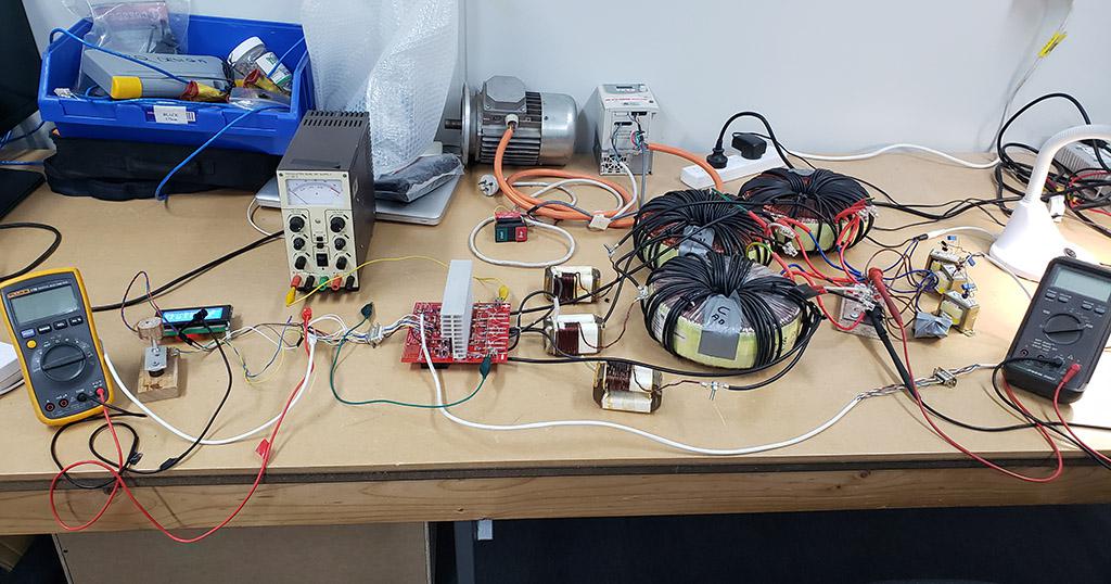 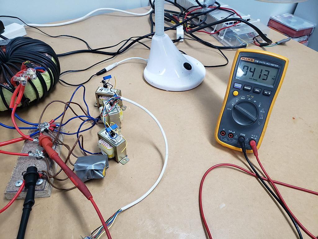 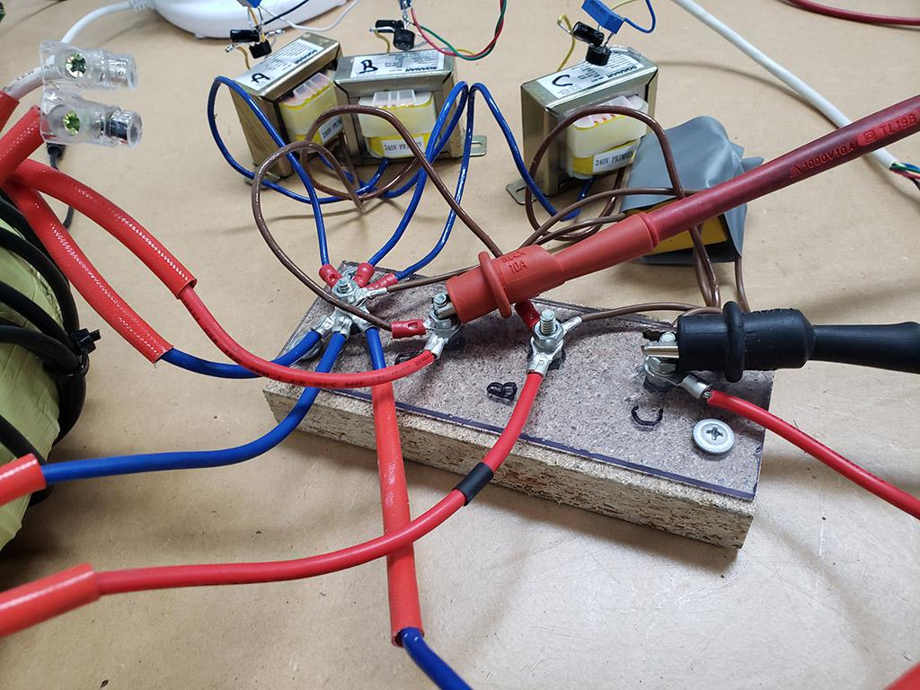 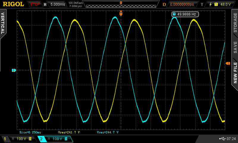 Edited 2022-07-22 11:15 by poida wronger than a phone book full of wrong phone numbers |
||||
| Revlac Guru Joined: 31/12/2016 Location: AustraliaPosts: 961 |
That looks good peter,  I expect the idle current to improve a little after adding some capacitance on the DC bus, it worked that way for the single phase, I think we might need more than 1 metalized polyester capacitor to help with the 20Khz, perhaps, will wait and see  I don't have a STM32F401 Black Pill yet. Cheers Aaron Off The Grid |
||||
| Haxby Guru Joined: 07/07/2008 Location: AustraliaPosts: 418 |
This is what it's all about. Great work! 22 odd watts per phase is about what I would expect with off-the-shelf transformers. Are they 60uH chokes? How many turns make 60uH on those cores? |
||||
| poida Guru Joined: 02/02/2017 Location: AustraliaPosts: 1388 |
I tried 2x and 1/2 DT and still got the 1.1 Amp draw at idle so I expect deadtime is not that critical with the parts I used and 1us deadtime as standard. The 3 Vfb signals are badly effected by EMI and useless. Some signal conditioning at the microcontroller board is needed. I made Vfb from a 240 ->6V transformer/diode bridge/1uF cap and 10K trimpot voltage divider, then the now 0.55V DC signal is taken back across the entire calamity to the control/power board. Measuring the signal with the DVM shows it to be 0.55V but there is a LOT of EMI present. So there was no closed loop control of the output, just direct control of all 3 phases via the pot. All three phases are different voltages, differing by 2 Volts or so. I want to eventually have them all the same from using individually adjusted PWM duty for each phase. Then we have a balanced 3 phase voltage output. For a start I could have Vfb = 3.0V instead of the 0.55V I use for some dumb reason. (I confused 0.55 as volts when it is in fact 0.55 x 5V ..) The Black Pill micro is 3.3V based so analog voltages need to be no more than this. So 3.0V for 240V output will give a bit of headroom but give 6x the signal for the same noise. Next week I do this, work permitting.. Edited 2022-07-23 09:50 by poida wronger than a phone book full of wrong phone numbers |
||||
| Haxby Guru Joined: 07/07/2008 Location: AustraliaPosts: 418 |
Tight placement of components is key to decrease EMI. With no power supply caps, the whole thing might be acting as a transmitter. To decrease EMI I strongly suggest: 1. Put low value film type caps on the PCB bus bars, and install the electrolytics. I used 3 of the 1uf film caps that came out of aerosharp inverters. Very low ESR. Nice and close to the IGBTs. 2. Place the 3 chokes as close as possible to the 3 output terminals. There is a fast dI/dT and dV/dT right at the MOSFET legs. You want to convert it to a slow sinewave using the chokes, with the shortest amount of antenna wire between IGBTs and chokes. 3. Get the black pill within millimetres of the driver chips. I'll be designing a carrier board to do this. Don't run logic signals off the board. Don't even run the micro power supply off the board. Keep it all compact and on board. 4. Vfb wiring needs to also be short between the transformers and microprocessor. I'm talking 3cm at most. Use small transformers. I have some TV1013-1M that might work. They have a 0.5+- output. I can send you 3 of them. I wonder if the +-0.5v output can go directly into the micro through a resistor without being rectified. The micro may tolerate the negative voltage. Many are ok with their pins going negative 0.5v |
||||
| Haxby Guru Joined: 07/07/2008 Location: AustraliaPosts: 418 |
Regarding Vfb, thinking about it some more, maybe something like this will work, using the little current transformers.  |
||||
| poida Guru Joined: 02/02/2017 Location: AustraliaPosts: 1388 |
thanks for hints on EMI Important fact re. Black Pill We must be able to remove the module to program it or reprogramming The Arduino IDE + STM Cube combo needs us to hold the cpu between fingers when entering DFU mode (needed for programming) The Black Pills have non-optimal results entering DFU mode. We need to alter the cpu/cpu temp sensor/cpu clock/something!! by holding it between fingers while pressing the two buttons in sequence. So forget about soldering the Black Pill module in place. The wiring of the primaries has all chokes leading to FET outputs and it has all toroid primaries leading to FET outputs. I accept the long antennas and their hard work making EMI I probably will get a RC low pass filter soldered on the Black Pill leads for the 3 inputs. I notice the 4th input, from the pot is quite quiet EMI speaking... This is not a critical ALL ALARMS CALL FOR HELP here, more a chance to develop some nasty but functional hacks to deal with the problem. I agree that part placement and signal/ground/Vdd routes can be singularly effective. Next week I play with this again. Still looking forward to closed loop control maintaining 3 phases to 1 V AC I can do this... wronger than a phone book full of wrong phone numbers |
||||
| poida Guru Joined: 02/02/2017 Location: AustraliaPosts: 1388 |
Haxby, I have 13 turns on each of the chokes. Since the heatsink is getting warm during 5 minutes of zero load at 240V AC output I was wondering if there is a bit of shoot through. The DT test I did earlier suggest not. I put a current sensor on the DC supply and with the board having no DC bulk caps installed I should be able to see high current spikes at the start and or end of each PWM event. I only saw typical ramps up in current, no large spikes. Maybe the IGBTs have a relatively large ON resistance compared with FETs.. Something is making the heatsink warm up wronger than a phone book full of wrong phone numbers |
||||
| poida Guru Joined: 02/02/2017 Location: AustraliaPosts: 1388 |
I have a usable Vfb now. The 6V AC -> diode bridge -> 10K trimpot is now set to 3.0V This winds past the EMI sources piking up lots of crap and back to the power board. This signal now goes to a RC low pass filter, 2K2 and 10uF soldered direct onto pin A0 (and A1, A2) on the Black Pill. Noise is about +/- 2% Now I can start work on closed loop control. I want to control each phase's output voltage and keep it tight to about +/- 1V of each other. I will need lower noise levels than above... (then after that, put in the soft start/stop and PID control, test that a bit and then add the bulk caps, test again, then finally hook up the proper power supply and see if it can run the motor) I need some more parts from home so that's today's work done. wronger than a phone book full of wrong phone numbers |
||||
