
|
|
Forum Index : Electronics : Time for a new Warpinverter build
| Author | Message | ||||
| Warpspeed Guru Joined: 09/08/2007 Location: AustraliaPosts: 4406 |
Your figures look excellent Roger. Its now a case of seeing what wire and winding method will best fit onto the respective cores. There is another handy on line calculator that tells you how many round wires will fit through a given sized hole. https://www.engineeringtoolbox.com/smaller-circles-in-larger-circle-d_1849.html Assuming you have completed fitting sufficient secondary layers to leave an 84mm hole remaining for the 22 turn primary. You can plug the numbers into the above calculator, and by trial and error find the largest diameter round wire that will go through the 84mm hole. The calculator says 15mm diameter will fit. So we go to the Tycab website, and look at automotive cables. These have thin insulation, welding cable is the same stuff, but with thicker double insulation that we don't need. https://www.tycab.com.au/battery-starter/ Click on specifications tab. We find that ABC191003 cable is 14.5mm outside diameter and 64.5mm squared copper. Secondary current 60 amps. Primary current 60 x 225/44 = 307 amps Current density in wire 307amps / 64.5mm sq = 4.75 amps per mm sq We designed our secondary for 4 amps per mm sq so 4.75 amps per mm sq is only slightly higher, and the large wire is pretty well exposed for cooling airflow between the turns, so its not going to overheat. That is going to be a very nice transformer that will run only very slightly warm at 14Kw continuous ! The same procedure will work for the smallest transformers, but the second inner winding will be the secondary. For sixty amps we need about 15mm sq wire. ABC119203 looks good. 13.5mm sq and 7.2mm outside diameter. We can run the current density up a bit, as it will cool well being exposed. That would offer a neater and easier to wind alternative to a bundle of six strands of 1.8mm diameter copper wire. Cheers, ĀTony. |
||||
| rogerdw Guru Joined: 22/10/2019 Location: AustraliaPosts: 801 |
Thanks Tony, that is encouraging. I don't think I would have been able to understand all the details if I'd got them all at once ... drip feeding is a little easier for me to comprehend. Those online calculators are awesome too ... save an enormous amount of time from trying to do it the hard way ... and just knowing where to find them is gold. I shouldn't have but I was having trouble working out the theoretical sizes needed for the primary winding wires, so thanks for spelling it out for me. It's a real relief when it's coming from someone who knows their stuff and I don't have to second guess every calculation I make, so thanks again. I'll send off a couple emails for prices and see how I go. Cheers, Roger |
||||
| Warpspeed Guru Joined: 09/08/2007 Location: AustraliaPosts: 4406 |
Its all quite logical, but there is quite a bit of ground to cover. The basis is to try to achieve equal copper volumes in the primary and secondary, if you can achieve that, the current density in the wire will be the same on both sides, regardless of the turns ratio. The starting point is allot half the total winding area to primary and half to the secondary, and with a toroid that will be 70.71% of the starting diameter sets the theoretical boundary between primary and secondary. The big wire can never fill the available space quite as efficiently as the small wire, but it should work out close enough to achieve a very practical solution. Its one more reason for putting the higher voltage winding on first, it will have less cooling, than the exposed fat outer wire wound over the top. The trick, if you can call it that, is estimating what will actually fit compared to what should in theory fit onto the core. Early first attempts at winding transformers can be quite disappointing as to how many layers will go on, because the wire never sits quite flat, and the turns never sit precisely side by side with zero clearance between. So be very generous when allowing how many turns will fit over a given circumference of core. It seems easy winding the very first layer, but every extra layer shrinks the available circumference by at least six turns, possibly more when you add additional insulation between layers. Its all fascinating stuff, and you will have picked up some very valuable skills along the way. Cheers, ĀTony. |
||||
| Warpspeed Guru Joined: 09/08/2007 Location: AustraliaPosts: 4406 |
The Tycab cables are manufactured in Melbourne, but they will not sell to you direct. You need to go to an electrical retailer in your suburb. They will order it in for you. A standard sized roll is 30 metres, and it ain't cheap. If you need less, they will cut it for you, and then charge you about double. Another way to buy the thicker cable is the orange welding cable, its the same price, but they sell it by the metre. The problem with that is it has an orange second outer layer that will need to be stripped off to reduce the outside diameter. Its a bit of a nuisance, but if the length is very short its sometimes worthwhile. Its helpful if you know how much length 22 turns + tails actually is, and buy your cable accordingly. Try winding it first with some suitably sized rope, or plastic hose to get a good estimate of the required length. Cheers, ĀTony. |
||||
| rogerdw Guru Joined: 22/10/2019 Location: AustraliaPosts: 801 |
Yes, I can recoginse many of the steps ... but there are a lot I had no idea about, so I really appreciate the guidance, thank you. I've only ever wound one transformer ... and that was an old microwave oven transformer that I rewound as an isolating transformer for when I work on live chassis equipment. That was 35 years ago and I still use it every day ... though it lives under my bench and I mainly use it as a foot stool nowadays. It's the perfect height and heavy enough that I just keep it there. When I wound it I brought out a heap of tappings and am able to switch it from 140V right up to 260V ... which has been very handy for various fault finding exercises ... though I do have a number of variacs now, so not quite as necessary. I have wound maybe a thousand coils or so, for motorcycle alternators ... so I've had some experience with the sizing and spacing of wire up to 2mm or so. My thumbs get nervous every time I think about it though.  Whoops, I've already sent them an email. Hopefully they'll put me on to a distributer over here then. I visited a guy I know the other day who's into recycling and couldn't get over all the beautiful clean copper wire he was collecting. He has a cable stripping machine and cuts wire into 2ft lengths and feeds it through. Seems such a waste seeing it destroyed like that ... but at least it is being recycled. A lot of it was thicker than my thumb, so don't know what it had been used for. He also has mountains of old airconditioners and fans and electronics ... all sitting out in the weather getting all crusty. I could have some fun exploring all that lot. He's only about a kilometer away, and I go past most days on the school run so I can drop in any time. Now that you've given me some sizes to aim for with the primary windings, I will also check with him as he said I'd be surprised how often he gets good clean cable to strip. Cheers, Roger |
||||
| Warpspeed Guru Joined: 09/08/2007 Location: AustraliaPosts: 4406 |
That is what I did originally. They put me in contact with someone nearby, that already had a roll on the shelf. Cheers, ĀTony. |
||||
| rogerdw Guru Joined: 22/10/2019 Location: AustraliaPosts: 801 |
Yeah, I got a reply with several options to order from so just waiting on some answers. A question I'd also like some feedback on ... in the OzInverter builds, I see everyone using a resin coating of some sort to secure the windings. Some of the comments refer to it being added protection due to using second hand wire ... as well as to stop vibration and chafing of the insulation leading to breakdown. None of the toroids I've unwound have used any ... resin or coil paint ... and I am interested in any thoughts of whether to use it or not. I do have some resin here as well as 5 litres of flexible silicone coating for conformal coating of boards which sets pretty well ... so it's no real drama either way. Cheers, Roger |
||||
| Warpspeed Guru Joined: 09/08/2007 Location: AustraliaPosts: 4406 |
The Oz inverters have gone through a long period of development and optimisation, and a lot has been learned since the very early days. Some of the early inverters suffered from high idling power, and the transformers were sometimes noisy. Two main causes for that. The transformers were wound by reverse engineering commercial designs that ran at a much higher flux density than we commonly use in today's PWM inverters, and its now usual practice to fit a fairly large non saturating steel choke in series with the transformer. Quite a few different ideas were tried to eliminate the annoying transformer chirping and buzzing, including various coatings including epoxy to quieten the beast. A much better approach is to add extra turns to the transformer, and fit a series choke to tame the very high current spikes. A warpverter is an entirely different animal. No series choke required, and everything runs at a low switching frequency, and with a one Tesla design flux density the transformers should be all but silent. My own inverter uses E/I laminations not toroids, and it does buzz a bit, but toroids are much tighter, without the flapping laminations, and should run silent. If you wish to coat the windings, you certainly can do so without any disadvantages except for the obvious one that it will be very difficult to unwind later, if that ever becomes necessary. Edited 2021-02-04 17:34 by Warpspeed Cheers, ĀTony. |
||||
| Murphy's friend Guru Joined: 04/10/2019 Location: AustraliaPosts: 583 |
Ha, so says he who built a 100V input warpverter. Try to start up a 48V version of that beast, using torodial transformers, and you may change your no series choke required statement. Sadly, it cost me handfuls of mosfets to find that out. I'll get it going reliably eventually but its been a very long road so far. Good luck to all who intend to travel on that road. |
||||
| rogerdw Guru Joined: 22/10/2019 Location: AustraliaPosts: 801 |
Thanks Tony. I'm of two minds really, but I do have some time to decide. After unwinding a heap of AeroSharp transformers I don't know if I could face trying to unwind it and recover the wire ... maybe just attack it with an angle grinder and chisel to get back to a bare core. Over the years I've tackled many noisy rattly transformers by dripping coil paint into the windings and letting it set. Can solve a lot of problems if you're lucky ... but I don't know if that's the way to approach it here. So are you saying you think it requires a series choke to work without blowing mosfets ... or that by fitting one you have improved the reliability? And you are still having trouble keeping it going? Cheers, Roger |
||||
| Warpspeed Guru Joined: 09/08/2007 Location: AustraliaPosts: 4406 |
Roger, One way to do it might be to just wind it and then test it, and when completely satisfied take it around to a transformer manufacturing company and get them to dip it in transformer varnish and bake it in their oven. You get to choose between either clear varnish or black. Klaus has had endless problems with continual blow ups. The first issue was that by mistake he ordered a 32.768 Khz oscillator module instead of 3.2768Mhz oscillator module. The Warpverter tried to run at 0.5Hz instead of 50Hz, and as Klaus did not have an oscilloscope at the time, the reason it went bang every time power was applied, took us both some time to diagnose. So I sent him the correct frequency module, and the warpverter would run for a while, then spontaneously at random intervals go bang again. That problem was finally traced to plugging the oscillator module into an IC socket. These modules have four thin round wires at the corners, and definitely do not make good contact with an IC socket. I have been caught by that problem myself, its not obvious. If the oscillator stops, or fails to start, its possible for two diagonal mosfets to remain turned on continuously, and the inverter goes bang. Soldering the module direct onto the board fixed that problem. However Klaus is still having random blow ups, and neither of us have any idea why that is happening. This has all been going on for a very long time..... Its a real pity, because the workmanship he put into it is truly outstanding, its a real show piece. But there is still a very evil gremlin hiding in there somewhere. Edited 2021-02-05 10:23 by Warpspeed Cheers, ĀTony. |
||||
| rogerdw Guru Joined: 22/10/2019 Location: AustraliaPosts: 801 |
Ouch, that's gotta be painful. And you're right, the workmanship is top class ... I was trying to work out how I was going to be able to make my transformers look as neat as his. Certainly something to aim for. And I suppose he's nowhere near you so you can't get together and troubleshoot. The internet has allowed all sorts of collaboration ... but there are times when nothing beats eyeballs on projects to see things that may not be obvious otherwise. Regarding IC sockets, when I first started in electronics I always wondered why only a handful of products used sockets and as time went on, fewer and fewer were used. But after a while of seeing all sorts of ramdom and bizzare and often expensive faults occur simply due to dodgy sockets, I began to distrust them immensely myself. There have been many boards over the years where any time I saw one I immediately removed all the sockets and soldered the ICs in directly and solved the problem ... and also made it far more reliable for the future. At the same time, they certainly can help with troubleshooting ... but then it is too easy to get caught up in the 'valve jockeying' mode, rather than proper fault finding techniques. Cheers, Roger |
||||
| Warpspeed Guru Joined: 09/08/2007 Location: AustraliaPosts: 4406 |
Quite right, but Klaus is in Perth, I am in Melbourne, unfortunately. Cheers, ĀTony. |
||||
Haxby Guru Joined: 07/07/2008 Location: AustraliaPosts: 419 |
I'd suggest Klaus starts a forum thread on the blow-ups. I'm sure we can get to the bottom of the problem. Are the blow-ups at power-up, or just random? |
||||
| Warpspeed Guru Joined: 09/08/2007 Location: AustraliaPosts: 4406 |
Hello Klaus, are you out there ? Cheers, ĀTony. |
||||
| Murphy's friend Guru Joined: 04/10/2019 Location: AustraliaPosts: 583 |
I'm sure Roger does not mind if I add relevant info to his thread, he is after all at the enthusiastic stage I was two years ago - sadly lost a bit of that lately... Anyway, after the initial problems were sorted the inverter ran fine for some time. It was powering my house and also accepting up to 2KW of GTI back charging. Then one day I used my electric chain saw and the inverter went bang. This saw has a soft start feature so figure? Have not been able to get it to run reliably since. It was mainly blowing the #3 (small) transformer mosfet bridge, after much of changing parts and experimenting here did not find the problem so far. Latest plan is to re build the #3 and #4 drive assemblies to mimic the same layout that #1 & 2 drive has. That will be a while to have completed, have other jobs in the line to tackle first. Re the chokes, the big dual core transformer needed one, would blow mosfets on startup otherwise. We experimented with a 'swinging' choke for the #2 transformer, not sure how much it helps as my CRO is not fast enough to see clearly the switching edges. Another thing 48V version builders should consider are the 16 little isolated driver supply modules. They are not all created equal so it pays to get some early (they take a while to get)for testing. I used 15V modules. The small 200mA ones are no longer available. I found that the supplier still had 300mA versions so I have some of those on order for spares. These start up above 45VDC but can run at slightly lower voltage once going. I have some other modules here which needed 70VDC to start up and then ran down to about 60V. Perhaps wise to get a DC/DC booster module as well, the 15v modules I use don't seem to need it. But, there is another thing with these modules when they are run from a lower DC than their designed mains input voltage. They do NOT start up all at the same voltage! Now, with 8 half bridges and therefore 8 DC/DC modules in the warpverter I do not think it is wise to start up the half bridge drivers at slightly different times. So I wired them so that they get powered *before* the main DC C/B is turned on. A LED tells me all low voltages (5V for control & 15V for drivers) are OK at which time I start the soft charge the caps sequence. Doing it that way will soft start the inverter reliably. If a AC volt meter is fitted one can see when the output voltage has risen to about 200V (depends on cap charging time) at which time the series start resistor is shorted out and the inverter can handle full power. I did post a schematic of that a while ago after somebody else had startup problems. So, while we all know the warpverter will run without problems from a 100V battery with EI transformers, I personally know that is not the case from a nominal 48v battery and torodial transformers and somebody else is finding out also not yet from a 300V battery. Its not as simple a project as it appears, I had great fun building it though. Its not cheap to build either, at least not for this pensioner which is why I'm still at it, too painful to ditch the whole thing. While I'm in the suggestion mode Roger, also consider how you assemble the whole caboodle. Mine weighs 150kg so this is not something taken lightly  . .I took great care to have the toroids oriented so there is minimal magnetic coupling between them in the confined space they are in. I also made sure the whole lot gets well ventilated on those 40 deg.+ days we have in Summer. Winding the transformers is tedious, especially since there are four of them. But there are a lot more parts to make a warpverter and all need to be carefully considered before getting too deeply into it. Thankfully Tony is very helpful if one gets stuck but only so much help can be done long distance via internet. |
||||
| rogerdw Guru Joined: 22/10/2019 Location: AustraliaPosts: 801 |
I'm sorry to hear of the issues you're facing, it must be terribly discouraging after the money, time and effort you've put in. Like I said above, your transformer winding set the gold standard for this type of work ... something I certainly aspire to. Just so I have a chance to understand more fully ... what length of time are we talking that it ran fine? Something else I don't recall reading is exactly what sort of battery are you using. And it's interesting to hear that you also had a 2KW GTI hooked up as well. I see that the chainsaw incident happened while the inverter was running ... but Haxby asked a good question ... were all the other blow-ups since, at startup or while it was running? Cheers, Roger |
||||
| Haxby Guru Joined: 07/07/2008 Location: AustraliaPosts: 419 |
"CRO is not fast enough to see clearly the switching edges" That's your next step right there. You need to see what's going on, otherwise you will be changing MOSFETs forever. Don't give up! I had some really funky stuff going on where the gate to collector capacitance was causing havoc. Without the scope I would be blind to this. That's the voltage trace on the gate below. 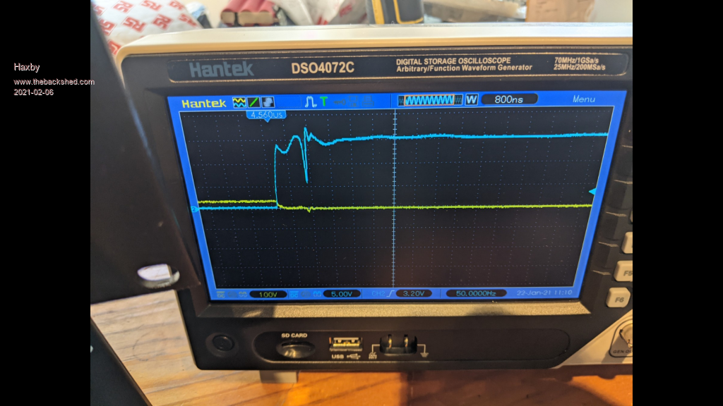 Also while newer MOSFETs and IGBTs are designed to switch on faster, the drawback is that the faster rise and fall times make the (seemingly small) gate to collector capacitance more significant, and in my case, the bounce got the igbt into the conducting region. Further, with the oscilloscope, I found that one of my gate driver ICs was a bit faulty. The on time was fine, but the off time was taking a long time. I had tested it on its own, driving a resistor, and it appeared to work, but I subsequently found the problem in-circuit when it was loaded with the capacitance of the gate of the igbt. All this stuff became very visible with the oscilloscope. |
||||
| Haxby Guru Joined: 07/07/2008 Location: AustraliaPosts: 419 |
I also have a separate circuit that energises the warpverter board and gate driver ICs before the main DC supply is turned on. It's good to know that the MOSFETs are being actively driven hard on/off before main power is applied. I'll be thinking about how it shuts down in due time too. Particularly if/when the overload trips. |
||||
| Warpspeed Guru Joined: 09/08/2007 Location: AustraliaPosts: 4406 |
All I can do is speculate, but there are two potential issues with toroids that I unwittingly avoided by using E and I laminations. The first is stray capacitance in the secondary winding, particularly in the largest transformer that has a step up ratio. Whenever the bridge switches, the secondary voltage creates an almost instantaneous 225v step change in voltage. Any capacitance down to the toroid (ground) needs to charge or discharge in essentially zero time, which can create a huge current spike in the primary. Andrew discovered that he had eighty amp spikes in his 24v primary ! Its a function of not only the capacitance between the secondary winding and the toroid, but also the turns ratio. This was something I had never seen in my own inverter, because the secondary on my E and I core is several narrow layers wound one on top of the other, not one very wide single layer wound right around a toroid. My turns ratio is 90v/225v or about 2.5:1 Andrews turns ratio probably about 22v/225v or possibly 10:1 I did look for current spikes after I became aware of this problem, and cannot now remember exactly, but they may have been four or five amps or something. So low as to be insignificant. Andrews transformer was quite small too, compared to the double stacked monsters some of you guys are running. So its something to be aware of. The smaller inverters have smaller transformers, and the turns ratio is less extreme, so its only the largest inverter that we need to be concerned about. Another issue is a start up current surge caused by remnant flux stored in the toroid. This is a real problem hard switching a big toroid directly to grid power, it can easily blow fuses or trip breakers. We should not have that problem for several reasons. But its also something to be aware of. Firstly we run a very low flux density, which greatly reduces the problem of flux doubling at initial power up. We also have some very large electrolytics in the dc supply to the switching bridge. These electrolytics absolutely MUST be brought up in voltage slowly with a soft starting resistor, and doing that also ensures we eliminate any transformer start up current surge. At power down, we simply switch off the dc to the inverter, and the voltage across the electrolytics slowly falls. That will feed a slowly diminishing ac voltage to the transformer which will effectively demagnetise the toroid. That never happens with a big toroid switched directly on and off direct to grid power. So provided we resistively soft start the inverter, there should not be any mosfet exploding current surges at power up. This may all be defeated by switching dc power to the mosfet bridges after the electrolytics, or by some other unusual modification that I cannot anticipate. I have tried to think this all through, and it should be completely trouble free, but there is always the possibility that something somewhere is working in an unusual or unexpected way and causing problems. Cheers, ĀTony. |
||||
