
|
|
Forum Index : Microcontroller and PC projects : Interrupt on analog voltage change on Analog Input pin?
| Page 1 of 2 |
|||||
| Author | Message | ||||
| Swartz Newbie Joined: 15/12/2020 Location: United StatesPosts: 18 |
I am new here. And am just getting started on the MicroMite2. I am considering using a simple circuit like this to put multiple switches on a single line. Vcc | |------R1-----R2-----R3--------- | | | | sw sw sw | | | | | Ain ------------------------------- | | R4 | | Gnd The idea here is that simple resistor ladder voltage at Ain will change depending on which of the switches is closed. And from the level on Ain -- will be able to deduce which switch is closed. Motivation for doing this is : * use minimal pins (actually one pin) for a small number of switches. So in order to make this work, ideally I would like to attach an interrupt function to Ain. Is that possible? If there is some documentation or prior post that can help me address this question myself, I would be happy to be directed there. As mentioned, I am very new to this device and am not completely certain I have my hands on all the documentation / samples / etc. Thanks, in advance. Swartz |
||||
| Mixtel90 Guru Joined: 05/10/2019 Location: United KingdomPosts: 7833 |
How about making sure that the minimum input voltage is greater than the minimum digital "1" input. Then, define the pin as digital input with an interrupt on it. In your interrupt routine define the pin as analogue and read the voltage then define it as digital again and end the routine. You can decode the analogue voltage somewhere in your program. Mick Zilog Inside! nascom.info for Nascom & Gemini Preliminary MMBasic docs & my PCB designs |
||||
| Swartz Newbie Joined: 15/12/2020 Location: United StatesPosts: 18 |
This is a very interesting idea! I will also chase this approach around. I do very much appreciate this insightful idea! Thanks Swartz |
||||
| RetroJoe Senior Member Joined: 06/08/2020 Location: CanadaPosts: 290 |
@Mixtel, clever... but wouldn't this digital threshold approach only detect the transition from an "All Switches Off" state to a "Not All Switches Off" state? I'm guessing the requirement would be detecting any delta in the ladder output voltage I.e. for any permutation of switch positions. @Swartz, what makes an interrupt-driven design necessary? Polling the voltage seems like the path of least resistance (see what I did there?  ) )If you are not married to the analog idea, and your goal is simply to "save pins", then you can use a 74LS148 8-to-3 encoder. I would think that an "all digital" approach would give you a more reliable read of the switch positions. BTW, Steve Wozniak would *not* approve - he was notoriously stingy about adding unnecessary parts. As a result, the Apple II is chock full of clever tricks e.g. a 556 timer chip coupled with a precisely-timed 6502 subroutine to determine the position of up to four paddle controllers. Enjoy Every Sandwich / Joe P. |
||||
| Mixtel90 Guru Joined: 05/10/2019 Location: United KingdomPosts: 7833 |
I *think* the chip has schmitt trigger inputs, so the switching point is defined. You're quite right, it interrupts on a low to high transition on any voltage above the trigger point. Then just read the voltage while it's an analogue input. You can use a Switch/Case to figure out which button it was. Of course, it'll only detect the button giving the highest voltage. Found it. 0= less than 0.65v 1= greater than 2.5v (I think these are right) So the input voltage with the *last* button pressed has to be 2.5v or more. The full 3.3v with the *first* button pressed. When the button is released the value read will be 0. Edited 2021-02-26 08:42 by Mixtel90 Mick Zilog Inside! nascom.info for Nascom & Gemini Preliminary MMBasic docs & my PCB designs |
||||
| vegipete Guru Joined: 29/01/2013 Location: CanadaPosts: 1129 |
Perhaps a timer interrupt that checks the analog button port every 10 or 20 milliseconds would work. Visit Vegipete's *Mite Library for cool programs. |
||||
| Zonker Guru Joined: 18/08/2012 Location: United StatesPosts: 767 |
I remember seeing this from TZadvantage a while back... Nice circuit... 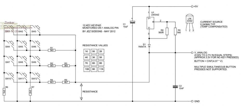 |
||||
| robert.rozee Guru Joined: 31/12/2012 Location: New ZealandPosts: 2428 |
this is a similar version: https://www.thebackshed.com/forum/ViewTopic.php?TID=6418 cheers, rob :-) |
||||
| Swartz Newbie Joined: 15/12/2020 Location: United StatesPosts: 18 |
Thanks gents! After considering all the really great guidance, I have reconsidered my approach. Though I will reserve in my back pocket the ideas given. This place is really great forum (active and responsive users) I have dashed the resistor ladder by finding more pins that I can utilize for digital inputs while also preserving as many special function "port pins" as I could. reset n/a 1 28 analog power n/a * digital input 2 27 analog ground n/a * digital input (SPI OUT) 3 26 digital input (PWM 2A) * * PWM 1A 4 25 digital input (SPI CLOCK) * * PWM 1B 5 24 digital input (PWM 2B) * * PWM 1C 6 23 digital input * COM 1 enable (r) 7 22 5V COM 1 RX (r) gnd n/a 8 21 5V COM 1 TX (r) * digital input (COM 2 TX) 9 20 n/a * digital input (COM 2 RX) 10 19 n/a console TX n/a 11 18 5V I2C DATA (r) console RX n/a 12 17 5V I2C CLOCK (r) power n/a 13 16 5V COUNT / WAKE UP / IR (r) * digital input (SPI IN) 14 15 5V COUNT (r) Requirements: 3 PWM 9 digital input * pins used NOTE: sacrifice SPI , PWM2 , COM2 (r) reserved NOTE: preserve COM1 , Console avoid 5V (n/a) not available So, I think I will give this pin layout a whirl. Thanks again so very much Swartz Edited 2021-02-26 15:56 by Swartz |
||||
| Turbo46 Guru Joined: 24/12/2017 Location: AustraliaPosts: 1638 |
If you can use two pins then something like this could work. Please excuse the rough drawing. 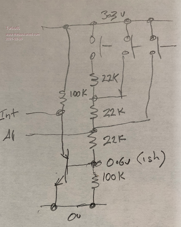 Bill Keep safe. Live long and prosper. |
||||
| Mixtel90 Guru Joined: 05/10/2019 Location: United KingdomPosts: 7833 |
I've just been experimenting with a micromite using the idea I presented earlier. I used a 1k pullup to 3.3v then experimented with pull-down resistors. I needed resistors of 470R or less, but resolution allowed values down to 10R easily (I couldn't test lower due to lack of bits) so a few buttons should be possible. 0R also works, of course. The test routine was: fkeys was set to the input pin number Setpin fkeys, intl, ibutton Do 'temporary nothingness Loop Sub ibutton Setpin fkeys,ain x=pin(fkeys) Print x Setpin fkeys, intl, ibutton end Sub Operation was pretty clean. There's a 100nF capacitor from the input to ground, which probably helps, although I didn't test without it. Mick Zilog Inside! nascom.info for Nascom & Gemini Preliminary MMBasic docs & my PCB designs |
||||
| Swartz Newbie Joined: 15/12/2020 Location: United StatesPosts: 18 |
Pretty cool, Mixtel90! Your approach would save me 3 digital inputs and trade those for one single analog input. I think this is an approach worth pursuing. Thanks so much! Swartz Just to confirm that I have your concept correctly stated as a circuit: Vcc | | R1 - 1K | Ain----sw----sw----sw | | | | | R2 R3 R4 cap | | | | | | | -------------------- gnd sw not in series parallel connected to Ain Edited 2021-02-27 06:39 by Swartz |
||||
| Mixtel90 Guru Joined: 05/10/2019 Location: United KingdomPosts: 7833 |
Yep, that's the idea. I didn't use any actual switches, but just put resistors between Ain and ground. Values were just what I had to hand. :) You could use a series string with buttons to ground from each junction. Alternatively you could switch each resistor to ground with the common on Ain. You could probably turn the whole lot upside down as your original drawing, in which case use inth instead of intl for the interrupt. Note, I've not tested this on a CMM2 as I haven't got one. It should work though. Edited 2021-02-27 06:58 by Mixtel90 Mick Zilog Inside! nascom.info for Nascom & Gemini Preliminary MMBasic docs & my PCB designs |
||||
| Mixtel90 Guru Joined: 05/10/2019 Location: United KingdomPosts: 7833 |
Just a followup in case this is useful to anyone. I'm incorporating this into a lab power supply design that I'm working on, doing the instrumentation at the moment. I'm using a 28-pin Micromite and a ILI9341 (with a faulty and disabled touch controller). There is a 4 button "soft key" menu. The input has a 1k pullup to 3.3v and the four buttons to 0v have 0R, 120R, 330R and 470R resistors. It's working very nicely. :) Input to the pin with the 470R resistor is about 1v. I tried 680R and 1k but they don't work. I used a select case with ranges for the pin() value to give the button numbers 1 to 4, with case else as 0. Individual routines called by the buttons also set the button number to 0 so that it is ignored by other routines. I've not needed to do any further debouncing. Thanks for making me think about it, Swartz. :) Mick Zilog Inside! nascom.info for Nascom & Gemini Preliminary MMBasic docs & my PCB designs |
||||
| Volhout Guru Joined: 05/03/2018 Location: NetherlandsPosts: 5036 |
If you ever need a similar solution and do not have an adc pin, you can make an rc oscillator in software interrupt driven. My default solution with a pic16f84 Edited 2021-02-28 08:33 by Volhout PicomiteVGA PETSCII ROBOTS |
||||
| Turbo46 Guru Joined: 24/12/2017 Location: AustraliaPosts: 1638 |
@Mixtel90, Can you please explain your circuit a little more. If I am correct, you have a pullup resistor of 1K and the largest switched pulldown resistor is 470R. That would give about 1 volt at the analogue input pin as you say but you need a digital input of less than 0.65 volts to give a digital zero to generate an interrupt. Or are you not using an interrupt? A pullup resistor of 2K5 instead would give about 0.5 volts at the pin and should reliably generate an interrupt. The analogue resolution would be less but it should work OK. Around a count of 160 bits for 2K5 and 470R - 120 bits, 47 bits and 0 for the other values. I like the idea!  Bill Keep safe. Live long and prosper. |
||||
| Mixtel90 Guru Joined: 05/10/2019 Location: United KingdomPosts: 7833 |
It was just done experimentally, Bill. I know the spec says low is 0.65v and high is 2.5v, but I managed a reliable high to low interrupt with 1v. I'm not saying this would work with every chip so it's not a commercial approach, but for my purposes it's adequate. As you say, a higher value pullup would be better. I might do that. An even better approach might be to use a low-high interrupt with a pull-down resistor. That way you have a slightly wider window of 0.8v from 2.5v to 3.3v to play with, which would be within spec. I would have done this but the veroboard was already done for a scanned system - I only needed to change 2 resistors. :) The interrupt system seems to work very nicely. It's cheap on pins and doesn't need much software either. I like cheap.... Edited 2021-02-28 21:10 by Mixtel90 Mick Zilog Inside! nascom.info for Nascom & Gemini Preliminary MMBasic docs & my PCB designs |
||||
| Mixtel90 Guru Joined: 05/10/2019 Location: United KingdomPosts: 7833 |
@Volhout Yeah... I remember seeing a similar thing. I used a RC to measure the value of a pot like that. I don't think I ever tried buttons. It was early days and I was at the stage of copying PIC programs into a 16C84 to play with. :) I remember cooking one... :( Mick Zilog Inside! nascom.info for Nascom & Gemini Preliminary MMBasic docs & my PCB designs |
||||
| Volhout Guru Joined: 05/03/2018 Location: NetherlandsPosts: 5036 |
Depends on the silicon. The PIC32 may have 0.65V and 2.5V. But the Armmite has 1.0V and 2.3V. So if your design is critical, it may not be portable. PicomiteVGA PETSCII ROBOTS |
||||
| Swartz Newbie Joined: 15/12/2020 Location: United StatesPosts: 18 |
Hello Sirs - Continuing to follow along. I have created a small chunk of "programmable hardware"  Many header pins to allow me to play with different ideas presented here. Since its only resistors I can determine which polarity I use for the power pins. What a great forum this is! Thanks so much! Swartz With 2.5k pull up and 470 in the "series ladder" Ain 3.3 1.19 0.91 0.53 So should have problem with interrupt to a low. Are these deltas able to be resolved ? (Admittedly a noob question. I am off to learn more about A/D) Unless I see an exception thrown by you gents - I am off to rotary encoder I/O board Cheers! Edited 2021-03-01 07:21 by Swartz |
||||
| Page 1 of 2 |
|||||
| The Back Shed's forum code is written, and hosted, in Australia. | © JAQ Software 2025 |
