
|
|
Forum Index : Microcontroller and PC projects : ArmmiteF4 User Manual
| Author | Message | ||||
| lizby Guru Joined: 17/05/2016 Location: United StatesPosts: 3362 |
Manual says this: "BLIT WRITE will copy the memory buffer '#b' to the display. The destination coordinate is 'x' and 'y' using the width/height of the buffer." But it appears (with ARMmite MMBasic Version 5.07.00b12, firmware dated April 11) that BLIT WRITE still requires the width and height of buffer area, unlike on the CMM2. The previous F4 manual showed this. Was an update to the firmware intended (or did I miss it)? (Incidentally (or not) on the F4, preprocessing or the program editor changes SPRITE SHOW to BLIT SHOW, which is illegal; it would be better if it changed it to BLIT WRITE. (And maybe dropped any page parameter.) PicoMite, Armmite F4, SensorKits, MMBasic Hardware, Games, etc. on fruitoftheshed |
||||
disco4now Guru Joined: 18/12/2014 Location: AustraliaPosts: 1000 |
Draft 3 of the Armmite F4 Manual. Should include all corrections identified previously plus other refinements. The hyperlinks in the contents should work and by clicking go directly to the section. The contents are also available as bookmarks to allow easy navigation. Armmite F4 Manual.pdf Regards Gerry Just a note to record the Options used to export to PDF from word2016 so that bookmarks are created 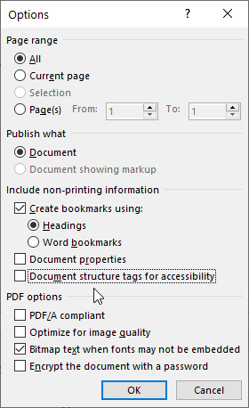 Edited 2021-05-22 16:28 by disco4now Latest F4 Latest H7 FotS |
||||
Chopperp Guru Joined: 03/01/2018 Location: AustraliaPosts: 1096 |
Excellent work Gerry. ChopperP |
||||
| Mixtel90 Guru Joined: 05/10/2019 Location: United KingdomPosts: 7873 |
Luvverly stuff, Gerry. :) Thanks! Mick Zilog Inside! nascom.info for Nascom & Gemini Preliminary MMBasic docs & my PCB designs |
||||
| lizby Guru Joined: 17/05/2016 Location: United StatesPosts: 3362 |
Thanks very much for this. This is a very valuable resource. Still (and sorry) . . . "BLIT READ [#]b, x, y, w, h[,pagenumber] Set the pagenumber to FRAMEBUFFER to read from the framebuffer -- see the FRAMEBUFFER command" I searched for FRAMEBUFFER and these are the only occurrences, so I think "[,pagenumber]" is a holdover from the CMM2. PicoMite, Armmite F4, SensorKits, MMBasic Hardware, Games, etc. on fruitoftheshed |
||||
| Chopperp Guru Joined: 03/01/2018 Location: AustraliaPosts: 1096 |
Hi Gerry I couldn't find any reference in the F4 manual to MM.BACKUP & RTC Memory refered to from matherp about 2/3 of the page down here This was a while ago now so some things may have changed. Brian ChopperP |
||||
| disco4now Guru Joined: 18/12/2014 Location: AustraliaPosts: 1000 |
They are not use from 5.07 onwards. This RTC memory is now used for storing the OPTIONS (80 Bytes) and VAR SAVE variables (4K). This freed up flash for the enhancements in 5.07 Has been updated for next release/draft. no reference to pagenumber or Frambuffer. BLIT READ [#]b, x, y, w, h is correct syntax Gerry Edited 2021-05-25 09:08 by disco4now Latest F4 Latest H7 FotS |
||||
| Chopperp Guru Joined: 03/01/2018 Location: AustraliaPosts: 1096 |
Re-read Peter's first post on the F4 update thread.... I missed that bit. I use MM.BACKUP with one of my F4's. Will obviously need to do some major changes to the program before I get around to updating the firmware. ChopperP |
||||
TassyJim Guru Joined: 07/08/2011 Location: AustraliaPosts: 6269 |
TIMER function The resolution is actually only 1mS, not uS Hopefully, the firmware can be changed to match the manual! Jim VK7JH MMedit |
||||
| flasherror Senior Member Joined: 07/01/2019 Location: United StatesPosts: 159 |
Gerry, I have partially read Draft 3 and have some comments. Page 10 - "Typically, it will execute a program at up to 90,00 lines per second". Should be 90,000? Page 21 - Should include baud rate for USB console since this is the first section on USB console. I think default rate is 38400 not 115200? Page 22 - "Switching to Serial Console" section mentions that default serial baud rate is 115200 but not sure this is correct. I think it's 38400 when I tested with 5.05.08 Page 24 - "Using Serial Console via a USB Serial Converter" mentions that default serial baud rate is 115200. I am connected at 38400 with 5.07.00b12 right after flashing firmware. Also baud rate references on Pages 25,26 Page 31 (Board versions table) discrete misspelled Page 32 - Are serial (COM) port pins 5V tolerant? How about I2C? 5V tolerance should be discussed somewhere, saves having to refer to datasheet. Maybe add to Page 27 onwards? Page 180 - Highlight/bold "Do not do anything at this point" section because in a bad piece of UI design the STM32 Cube programmer prints "Download completed" message before it verifies it. First time I flashed I unplugged the board after I saw the message because I assumed it was displayed after verification. Also the following are my suggestions: 1. On Win7 for using the USB console, this requires STMicroelectronics Virtual COM Port drivers to be installed. (This driver is separate from the drivers installed with STM32 Cube Programmer software) Virtual COM Port drivers at www.st.com/en/development-tools/stsw-stm32102.html This could be added to Pages 21, 25, 181 2. Some older firmware versions do not support LIST COMMANDS and LIST FUNCTIONS. I believe Version 5.07.00b12 does but 5.05.08 doesn't. (Page 131) Overall the manual so far is fantastic and I hope these help improve it! Edited 2021-05-29 02:33 by flasherror |
||||
| lizby Guru Joined: 17/05/2016 Location: United StatesPosts: 3362 |
I think anything between 38400 and at least 115200 will work. I don't have to switch to 38400 after flashing. I believe all available digital pins are 5V tolerant. DAC1 and DAC2 are not. PC13, PC14, PC15 exhibit some squirreliness--best avoided. PicoMite, Armmite F4, SensorKits, MMBasic Hardware, Games, etc. on fruitoftheshed |
||||
| circuit Senior Member Joined: 10/01/2016 Location: United KingdomPosts: 276 |
When printed, (yes, I do print all the MM manuals) the table on page 11 splits overleaf to page 12 without column headers (Micromite Family). This is not so much of problem if the pages were facing pages, but they print overleaf. The table appears to fit on a single page so may I suggest doing a page split immediately after the text on Page 11, leaving a much more readable table on page 12. Alternatively, place column headers on the remnant of the table. Overall, congratulations on a most excellent and very welcome resource. I look forward very much to printing and binding the definitive edition. |
||||
| flasherror Senior Member Joined: 07/01/2019 Location: United StatesPosts: 159 |
Hmmm... The MMBasic boot message is displayed automatically on reset and does not wait on a keypress before it is sent, so the firmware cannot be doing auto-baud detection. Are you sure you didn't change your baud rate setting to 115200 after first boot? In another thread here [discussing ARMmite L4 (not F4)] Peter mentioned the baud rate is 38400, so I assume it might be the same thing with F4 firmware? Not sure why I'm seeing a different default baud rate unless there are multiple firmware versions with different default baud rate settings. Edited 2021-05-29 11:41 by flasherror |
||||
| flasherror Senior Member Joined: 07/01/2019 Location: United StatesPosts: 159 |
Something to discuss and possibly include: Possible warning for powering board via external 5V and using USB console: .jpg) On V33 PCB R25 was NOT a fuse (as shown on schematic) but 0 ohm resistor. This is a potential issue if board is externally powered (external 5V supply) and USB connected for USB console! PCB should have had Schottky diode to isolate USB 5V power from PCB 5V supply rail? (This is a similar issue for STM "Blue Pill" boards that was fixed in "Black Pill" revisions) Any suggestions for dealing with this? 1. Remove R25 - but means that board cannot be powered by USB 2. Remove R25 and solder a Schottky diode in its place (anyone have a part # that will fit here?) 3. Use USB isolator? 4. Forget about USB console and use Serial Console on 4-pin USART1 header. This would avoid having to modify the board but will require USB to serial converter. Edited 2021-05-30 06:57 by flasherror |
||||
| TassyJim Guru Joined: 07/08/2011 Location: AustraliaPosts: 6269 |
Firmware now matches the manual! Jim VK7JH MMedit |
||||
| flasherror Senior Member Joined: 07/01/2019 Location: United StatesPosts: 159 |
Nuts... After I posted I found that the issue is mostly discussed on Page 22 of Draft 3. However I would include Option 4 (use serial console instead of USB console if powering the board using external 5V power) in this section as I think it might be the easiest option. Edited 2021-05-30 09:37 by flasherror |
||||
| flasherror Senior Member Joined: 07/01/2019 Location: United StatesPosts: 159 |
Sorry if I'm posting a lot, but I happen to be exploring the ARMmite F4 at the moment. I thought I would share some more comments which might be useful in the manual. Link the following useful documents: General board info (for V2.0 but current v3.3 boards might be the same?) https://stm32-base.org/boards/STM32F407VET6-STM32-F4VE-V2.0 Useful pinout diagrams https://os.mbed.com/users/hudakz/code/STM32F407VET6_Hello/shortlog/ Suggestions for LCD display sections Some pins on J2 (PE7 to PE15) are also used for the FSMC connector and cannot be used by MMBasic regardless whether LCD is connected. This means that these pins can't be used for LCD RESET, DC, CS or touch controller pins. If you do you'll get a "Pin is Invalid" message when doing OPTION LCDPANEL command (see next) For display configurable pins (e.g. RESET, DC) you will get an error if attempting to use an invalid pin: >OPTION LCDPANEL ILI9341, LANDSCAPE, PE15, PE13 Error : Pin | is invalid (PE13/15 are invalid pins) Also, PC13/14/15 are not recommended for general IO use (potential SD card corruption?) Compare SPI connected display speeds with parallel displays (Circles per second) My ILI9341 SPI display does approx 55 circles per second Don't have a parallel display so can't check Add use of CLS with RGB easy color specifier cls(rgb(yellow)) clears screen with Yellow color I found yellow, green, blue, red, white, gray to be valid - are there any more? For ILI9341 2.8 (same one shown on P47), do you really need a LED backlight resistor if not using PWM to control the backlight? That is, can you directly connect LED pin to 5V. The schematics look like the LED has a 3.9 ohm resistor so no external resistor might be necessary? (despite what P48 of Draft 3 says) Edited 2021-05-31 11:57 by flasherror |
||||
| TassyJim Guru Joined: 07/08/2011 Location: AustraliaPosts: 6269 |
I can't answer your other questions but check the RGB() function for the available colour shortcuts. Jim VK7JH MMedit |
||||
| flasherror Senior Member Joined: 07/01/2019 Location: United StatesPosts: 159 |
I did some investigating for my 2.8" SPI display (labelled 2.8 TFT SPI 240x320 V1.2). This is the one (red board display) that is pictured on the Armmite F4 manual. 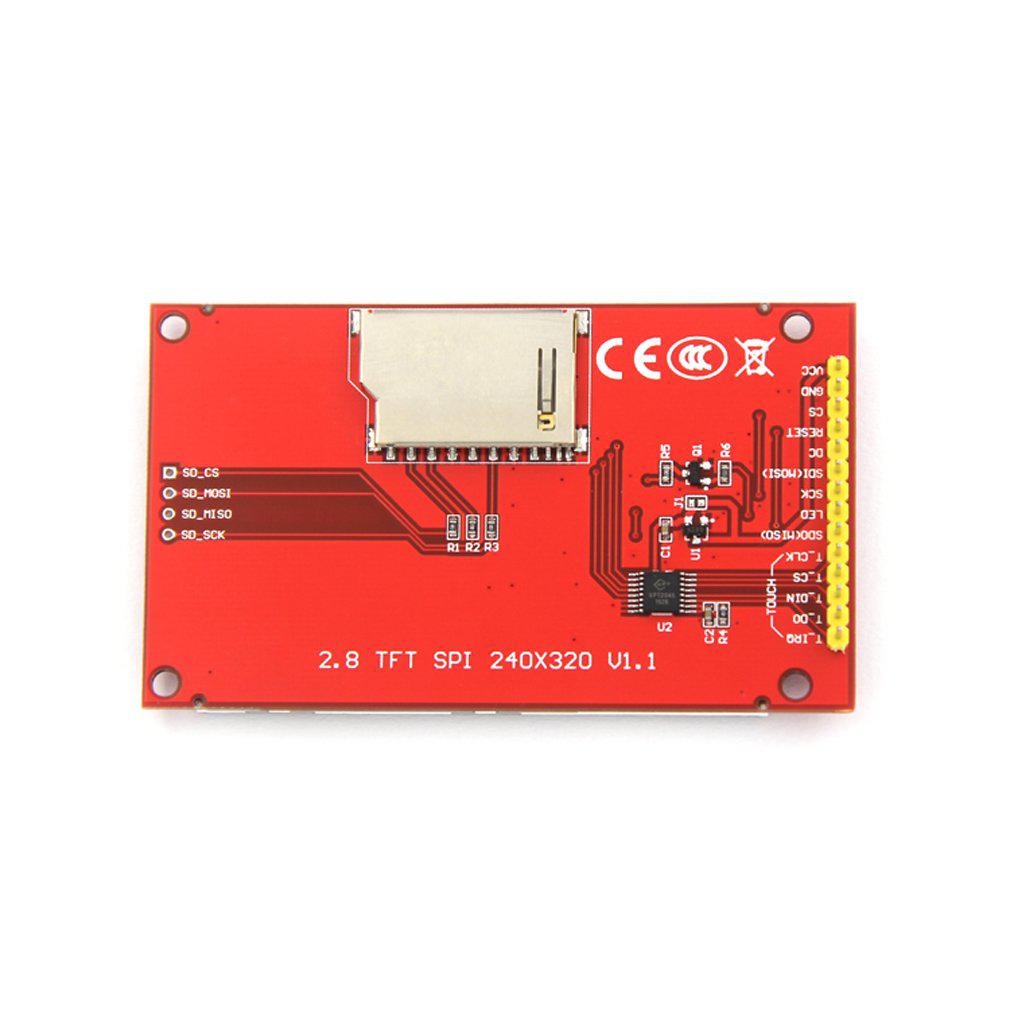 The above is a photo of v1.1 but it looks the same as V1.2 I think there may be a difference in backlight driver between previous V1.0 PCB revisions and newer ones. The only schematic I can find shows that the LED (anode) pin connects to the relevant display pin through a 3.9 ohm resistor. I do not actually have a V1.0 or V1.1 display PCB to check so I presume this is for pre-V1.1 displays. See image below:  backlight schematic section.jpg) But, for V1.2 of this display board, the LED pin drives a transistor which in turn drives the backlight through a 8.2 ohm resistor. This means that since the LED pin drives a transistor (with its own 1K base drive resistor) there does not need to be a current limiting resistor for the LED pin for V1.2 displays. Of course the presence of a resistor would not hurt anything but if I'm right V1.2 doesn't need the external resistor. Also, the backlight would probably be able to be driven directly from an I/O pin, no external driver transistor needed. See PCB image below (had to break out the digital microscope for this one): The original Micromite manual and Armmite F4 manuals indicate that this resistor is required, but this might have been because the earlier display version required one. The change in LED backlight circuitry means that V1.2 Backlight LED Anode voltage seems to from the VCC pin (haven't traced the circuit). Not sure if backlight will operate brightly if display is powered from 3.3V (and jumper J1 is shorted to bypass the onboard 3.3V regulator) I cannot find a schematic for V1.2 of this board, anyone have one? I would like to confirm the backlight circuit in V1.2 displays. Edited 2021-06-01 00:46 by flasherror |
||||
| flasherror Senior Member Joined: 07/01/2019 Location: United StatesPosts: 159 |
1. I think there is an incorrect reference to ST7735 displays in F4 Manual (Draft 3). The OPTION LCDPANEL command section on P110 does not list ST7735 display as an option, but on P69 ST7735 is mentioned: "MMBasic will automatically translate all colours to the format required by the individual display controller which, in the case of the ILI9341, ST7735 and ILI9163 controllers, is 65K colours in the 565 format" 2. Is it possible to use ST7735 SPI displays with ARMmite F4? Edited 2021-06-05 00:12 by flasherror |
||||
| The Back Shed's forum code is written, and hosted, in Australia. | © JAQ Software 2025 |
