
|
|
Forum Index : Electronics : all home built solar system
| Author | Message | ||||
| poida Guru Joined: 02/02/2017 Location: AustraliaPosts: 1389 |
Power board is completed. It is compatible with the nanoverter and the soon to come picoverter and Madness's control board. In other words it uses the 10 pin IDC connector we have used for years. (It even is compatible with Powerjack LF inverters too) Make sure you specify 2oz copper. I like and use all the time EasyEDA. The gerber files: Gerber_PCB_madboard 24.5mm v4.zip and this is what it looks like: PCB_PCB_madboard 24.5mm v4_2021-05-16-1.pdf I fixed a few things: TIP35C the high side TIP41/42 were swapped. The 18V zener was wrong. And the base pins for all 4 totem poles now have 10K pull down to keep then shut-the-hell-off during boot. Have fun and build a few and blow them up and sh!t.. wronger than a phone book full of wrong phone numbers |
||||
| poida Guru Joined: 02/02/2017 Location: AustraliaPosts: 1389 |
latest code for nanoverter. two nanos need two firmwares. nano1 does the heavy lifting, that is, run the inverter. This code has not changed for a long time. nano2 code oversees things and shows stuff on the LCD. I have many variations of nano2 code that is for I2C LCD, serial LCD, a AC curent sensor (that needs a simple hack on the nanoverter board) and others. so, nano1 code is nano_1_v7_no_bessel.ino.zip This works very well with the standard nanoverter build with the opamp based Vfb low pass filter. I use this code in my home inverter and its running this code for years now. nano2 code. Now it gets interesting. If you want AC current display, then try nano2_5_ac_current_sensor_continuous_on_off_control_softserial.zip AC current calibration is very tricky..if you don't want it just ignore it and let it display rubbish. You need to hack the nanoverter board a little to get the AC current display. I find it not very useful anyway so maybe pass on this one. This code uses a on/off switch that needs to be on continuously to run the inverter. This is what I use at home. It lets me control the inverter via a simple 5V signal from another microcontroller. Pull it down to ground = run, let it be 5V, stop inverter. It also needs a serial LCD (20 x 4 with a small firmware loaded into yet another nano that drives the LCD) A version that instead uses I2C for the LCD. No AC current sensor. I think it uses a momentary push button switch to start and stop the inverter. To change to continuously on/off switch is trival. nano2_4.ino.zip here is a version that uses one fan only, directed at the heatsink. I have the fan also blowing air past the toroid. I built an inverter with one fan so this code is for that. If either HS or toroid exceeds "fan on" temp, then the fan will run. (this version is used in the inverter that I started the air compressor, drawing 11kW during motor start up. The inverter build is a small enclosure so I did not have space for the second fan.) nano2_5_sserial_ac_I_sensor_on_off_cont_one_fan.ino.zip I have found that I2C interface to the LCD is very susceptible to interference. Once I changed over to serial - 9600 baud - LCD things got very stable. Sometimes even then I needed a inline ferrite choke on the 3 wires. The LCD is useful for me only to show if the inverter is running and what voltage in input and output. Maybe also to show if a fan is commanded to run. Serial LCD code: 2 flavours, one with a nano driving the LCD directly, the other driving an I2C equipped LCD. Since I had a few of both types, I made two versions. This code is for the third nano, which is connected to the LCD. IT then is connected to ground, 5V and A4 via the I2C 4 pin connector. This is the first 3 pins. The 4th pin is not used with the serial port code. for direct connection to LCD with 4 bit wide data, RS and Enable pins.. nano_serial_to_parallel_LCD_2.ino.zip and when using I2C type LCDs (note: your LCD might have a different I2C address than what is programmed in the code. So you must change it to suit if needed) nano_serial_to_i2c_LCD.ino.zip PM me with any issues with loading and running these firmwares. It's not very hard once you do it a few times. Important: note well which is nano1 and which is nano2 on the nanoverter board. confusing the two is not fun. Over the past year or so I have added a few extra things to the nano2 code. The latest code is something like: nano2_5_ac_current_sensor_continuous_on_off_control_softserial.ino.zip This uses the serial LCD. It has a timeout for low voltage cutout, I use 5 minutes. This means DC voltage has to be below LV cutout for 5 minutes continuously for the LV cutoff to trigger. It has the usual fan start, stop and inverter stop for heatsink and toroid over temp. This is the code I use to run the home inverter. The LV timeout is important, when a fridge switches on, DC voltage will momentarily drop rather low while the motor starts up. But then then battery voltage will return to something like "OK". I did not want the inverter to stop just because a fridge started. I want it stop when the battery really is lower than the limit when running under a smaller load that is what it delivers for hours on end. wronger than a phone book full of wrong phone numbers |
||||
| poida Guru Joined: 02/02/2017 Location: AustraliaPosts: 1389 |
powerboard PCB files Finally I need to upload this for anyone who is interested. The BOM is to be worked out by looking at the board. All parts are labelled in the top silkscreen. Except a couple, the 1N4148 gate diodes are not marked. These are D18,D17,d16 etc. I forget if any others are missing. Use HY4008 FETs. Buy more than enough to build 2 boards. You may well need the spares when the board blows. The 5 x 10uF 25V can be something larger if you like, maybe 47uf I used 25V 100uf caps. It ran well. My builds using these boards only used 4 x 4 Fets for the home inverter and 4 x 3 FETs for the test inverter. I see no need to build the full 4 x 6 FETs unless you expect heavy duty service. 6kW + for hours on end. This is a lot of battery and most people may not have this DC power available. 48V DC for best results. I do not support 24V or 12V builds. You will be on your own if you go there. it looks like this http://www.thebackshed.com/forum/ViewTopic.php?TID=13650&P=2#167180 11kW peak power with 4 x 3 HY4008 FETs http://www.thebackshed.com/forum/ViewTopic.php?FID=4&TID=9409&LastEntry=Y#166999#166980 PCB_PCB_madboard 24.5mm v4_2021-05-16.pdf gerber zip file Gerber_PCB_madboard 24.5mm v4.zip jclpcb loads the above gerber zip file and give me a price of $115 for 5 boards. You need to specify 2oz copper. 1.6mm board thickness is fine. $115 for 5 boards, using DHL express delivery. This is less than $25 a board. wronger than a phone book full of wrong phone numbers |
||||
| poida Guru Joined: 02/02/2017 Location: AustraliaPosts: 1389 |
time to play with the picoverter. I just ordered 5 boards. If all goes well I will probably use this to drive the home inverter from now on. PCB_PCB_picoverter 6 w lcd_2021-05-16.pdf 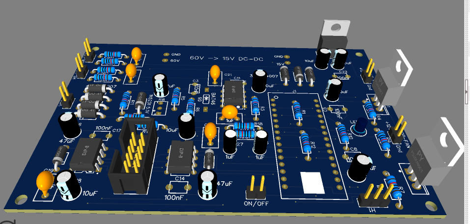 The code will support: LV cutoff, with timeout and optional restart Heatsink fan on, off and inverter stop on over temp Toroid fan on, off and inverter stop on over temp Optional LCD support, at 9600 baud (actually 10,000 baud. Let's see what I can get away with) It needs only one nano. A far simpler control board. It is compatible with the powerboards we all have, using the 10 pin IDC connector derived from the PowerJack LF inverters. Best results will be when using the totem-pole type powerboards. This is just a prototype. I plan to design another version of this board to support much better gate drive design and PCB implimentation and this will not use the IR2184(4) gate drive ICs. This second part of the project is still in the design phase and will need plenty of time yet. wronger than a phone book full of wrong phone numbers |
||||
| flyingfishfinger Senior Member Joined: 12/09/2020 Location: United StatesPosts: 102 |
Hi, This is also a cool project. I can help with the layout if you like - note that JLCPCB offers SMT assembly services now, and DOES have some through-hole parts as well if you feel like going that route. What state is this in, otherwise? Cheers, R |
||||
| poida Guru Joined: 02/02/2017 Location: AustraliaPosts: 1389 |
Hi FF the situation now is that the nanoverter board has been proven to work well. This is a control board running my firmware. The power board design above is not proven yet. It is almost identical to the board that ran 4 x 3 FETs at 11kW at 45V DC. The changes relate to silk screen errors, a dumb mistake with the 18V zener that is used to make 15V gate drive supply and 4 pull down resistors that ensure the FETs stay OFF during power up/brown out conditions. I could apply this fixes without moving anything on the first iteration PCB. I think it will work fine. Since it uses the same totem-pole drive as Madness's board, I expect it will run well with all 6 FETS installed. I just ordered 5 picoverter PCBs and once they arrive I will build one and complete the firmware for it. If I were you I would use this to control the powerboard. It will be a much simpler build. It will run the nano1 code as used in the nanoverter but with some modification. I think in a week the picoverter code will be completed and I will change my home inverter to use/prove it. Your output voltage of 120V is going to work fine with these. Other parts needed would include a small (wallwart?) 120V ->12V transformer for voltage feedback, a couple of large chokes that will not saturate at about 2x the maximum operating power levels, the transformer as described by InPhase. Starting your own thread would be a good idea since it keeps all your info in one place. I would prefer no SMD design since it's getting to the stage for me that even through-hole projects are beyond my eyesight. I like having most parts available at home when building a board. IF SMD there would need to be a few big orders of assorted passives. And you need to select them before soldering in place... wronger than a phone book full of wrong phone numbers |
||||
| flyingfishfinger Senior Member Joined: 12/09/2020 Location: United StatesPosts: 102 |
Hi Peter- Makes sense on the SMD, we don't want to make anyone's build a pain after all. We have the opposite issue though, no-one uses through-hole anymore around here. Consumer electroncs are approaching the use of 01005 components - that's 1 x 0.5 mm (!!!), but 0201 (2x1 mm) is still standard. Anyway, if you're open to some feedback on both the Nanoverter & Powerboard layouts I have a few minor suggestions (some aesthetic, one or two functional). If you're doing a new iteration of the Nanoverter perhaps we can collaborate? I would be happy to make some tweaks to the Powerboard myself & share before I order some for my inverter build as well. Cheers, Rafael Edited 2021-05-21 02:58 by flyingfishfinger |
||||
| nickskethisniks Guru Joined: 17/10/2017 Location: BelgiumPosts: 416 |
Maybe we can start a new thread about that? What would be your changes? I would like 2 extra outputs, 1 for activating a precharge relais/resistor, and 1 for shorting the precharge resistor. Good work on the pico board Peter, for me it would be a nice board to have for my testing rig. And for making a small, more portable inverter. |
||||
| flyingfishfinger Senior Member Joined: 12/09/2020 Location: United StatesPosts: 102 |
Very little, more of a suggestion for Rev 5 if Peter feels like it - I'm not here to derail the thread. I would just add ground planes to both boards, and remove all the 90 degree bends from the traces. The former will be good for noise / return current loops and the latter is a bit more aesthetic since this isn't a high speed board. If YOU want to start a new thread, I can definitely help with the features you want though. Not something I need for my inverter :) R |
||||
| Warpspeed Guru Joined: 09/08/2007 Location: AustraliaPosts: 4406 |
A plain vanilla inverter without any surface mount parts is DEFINITELY the way forward. Simple, fewest possible parts, easy to diagnose and repair, and cheap enough to just throw away if necessary. The KISS principle definitely applies. If someone wants to add extra monitoring, alarms, data logging, and a whole lot of fancy extra control and display features, that can be done completely external to the basic functional inverter block. Cheers, �Tony. |
||||
| johnmc Senior Member Joined: 21/01/2011 Location: AustraliaPosts: 282 |
Thanks Peter for the update. As Warpspeed quoted. "A plain vanilla inverter without any surface mount parts is DEFINITELY the way forward." My thoughts exactly. Cheers john johnmc |
||||
| wiseguy Guru Joined: 21/06/2018 Location: AustraliaPosts: 1000 |
Hi Nicks, my start up scheme currently just uses a small toggle switch. My method might not suit you at all, but perhaps it might so here goes. I use a 24V KiloVac relay (solenoid?) rated at 900V 500ADC for applying full current to the inverter power section, I paid $AUD ~ $111 most other Kilovac types are $200+ but the 24V one is a good price, They come from Digikey - I see the price is now AUD$139 and they are waiting on overdue stock . My inverter also has an 80A breaker from the batteries which is typically left on. When I turn the Inverter small toggle switch on, it applies 48V to the DC/DC converters for 12 & 5V for uC power etc. It also applies the 48V to a resistor in series with the Main inverter power board capacitors, the inverter soft start is inhibited for now. The circuitry now waits until the Vcaps on the power board are >95% of the input voltage (48V/50V whatever). When this threshold is reached the solenoid is commanded to pull in and the Inverter (soft start) is commanded to run The Kilovac is now driven by 2 sequential duty cycle trains which causes an average of 24V for pull in and then after a short delay (<500mSecs) reduces to ~7V for hold in. There are a few minor tricks to make it shut down nicely, but the short version is; turn off the small toggle switch, this triggers input VLow to be sensed which commands stop the inverter (soft stop), at the end of soft stop the solenoid is commanded to open and the inverter is now totally galvanically isolated from the battery supply. You can even leave the small toggle switch in the start/Run position and then close the 80A breaker. No splat or bang just a repeat of the above sequence, I haven't tried turning it off the same way, I prefer to just turn the small toggle to off and take advantage of the soft stop. I am reliant on Poidas help for a couple of software tweaks to make this all work nicely, but the same software should be able to be used without the Kilovac and using the old precharge approach. My Nano Pico version will have 3 sets of full bridge power drives and I intend it to have 3,6 & 9KW flavours but requiring a separate choke for each 3kW stage. I am designing my Power stage to be a 100mm x 100mm 1oz copper 1/2 bridge board with 3 high and 3 low side FETs of which I believe only 4 FETs total should be needed for 3kW. The Power drive scheme is the inverse connected opto LED drive that ensures no cross conduction can occur, followed by a buffered output . Note I currently use this method and on my power board easily achieve 5+kW with just 4 Fets per leg. Scalability for HF inverters has always been difficult/too hard, I hope to make it a relatively straight forward task with this topology. I am also opting for a small 2mA to 2mA output voltage sense transformer on my version of a nano pico and an over current, adjustable setting, latched stop. The reason for posting this is not as a boast but because some of these are current point of interest. If anyone has a wish list not covered here I am happy to receive input but can't guarantee it will sway my direction. I am also happy to share any files PDFs Gerbers etc I create with whoever wants to have a play too. Incidentally I forgot to add that it will be an all through hole design. Edited 2021-05-21 15:16 by wiseguy If at first you dont succeed, I suggest you avoid sky diving.... Cheers Mike |
||||
| nickskethisniks Guru Joined: 17/10/2017 Location: BelgiumPosts: 416 |
Wiseguy I missed your reply, thanks for your input, yes those kilovac relais are on my list, although I'm also considering mosfets for this. At the moment there are only breakers between my battery and inverter. I do use a 100R 25W resistor for precharging. There is a schaltbau dc relay between solar panels and mppt controllers, and I've got 2 more recycled but they draw a lot more current compared to those kilovac relais. I'm also considering an output relay on my inverter, I know the program has a soft start, but I ones read this could cause appliance failure, for instance with fridges. What is your opinion on this? I don't think it would harm those switch mode power supplies. But I'm not sure with others, that's why I wanted to include a relay, perhaps activated around 180V to reduce the inrush current to save the relay contacts. But a soft start seems to be more logic. Peter, for the first time powering up the nanoinverter, do I need to be careful when doing AC calibration? Can I expect overvoltage on the output or will it be ok? For the DC current sensor, I'm thinking of using this sensor; (will this be ok?) or do you recommend a uni directional for higher accuracy? ( I could be an opamp offset circuit if it were a problem, or other hack) LEM |
||||
| wiseguy Guru Joined: 21/06/2018 Location: AustraliaPosts: 1000 |
For interest if you havent done the calculations here is what the Kilovac requires. The 24V Kilovac has a 40 Ohm coil so running from 24V for pull in draws (24 x 24)/40 which is 14.4W, the "economiser" hold in at 7V becomes (7 x 7)/40 which is 1.2W I agree that during soft start with an older compressor style fridge, it might struggle to get going - I have no evidence to support this. A relay that operates either after a time delay from soft start begin or at a voltage threshold (why not use 200 or 220 as the threshold instead of 180?) I think would help ensure a good solid start. If you could turn it on close to the zero crossing (some wetting current is desirable) would be nicer to the loads & could help extend relay life. From memory I think the nano requires around 3V feedback to regulate the output. My approach is to temporarily apply 240V to the sense/feedback/transformer and wind the voltage adjustment for maximum ie 4V that is fed to the nano input (pin 19, A0) before applying power to the inverter, that way the output at first start up would be at minimum around 180V. I usually try to scale the feedback components so the maximum adjustment voltage range cant exceed 255/260VAC, Usually covering the range of ~ 180 - 255VAC. Edited 2021-05-26 09:19 by wiseguy If at first you dont succeed, I suggest you avoid sky diving.... Cheers Mike |
||||
| poida Guru Joined: 02/02/2017 Location: AustraliaPosts: 1389 |
The picoverter PCBs have arrived. I built one and it works perfectly. No errors on the PCB 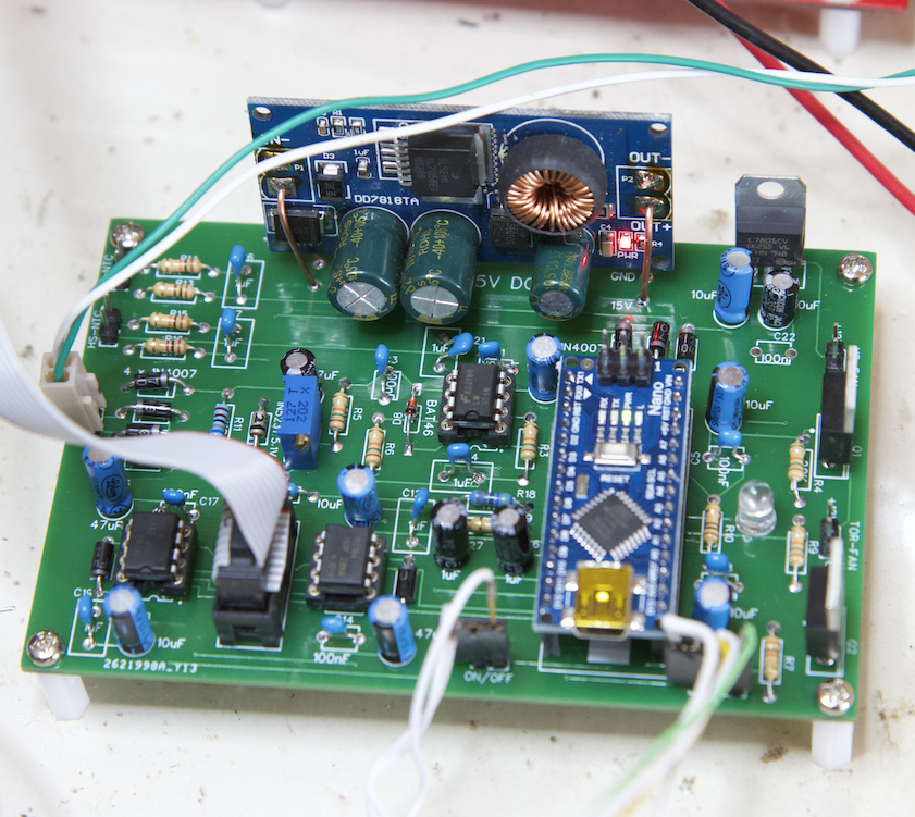 Later I will upload a BOM and build and startup instructions. The 12V AC feedback circuit draws 1.5mA at 10.3 V AC with my feedback transformer. the firmware: pico_1.ino.zip The PCB files have been posted earlier. The firmware works properly, with the LV cutoff and restart and the two over temp stop and fan controls. All good. Even the LCD works. The serial data is sent at 10,000 baud, due to the code that sends the data is within the 20kHz main interrupt loop. I divide by 2 for the bit transmission so that means 10,000 baud and not 9,600 baud. The nano/LCD that is running my serial LCD code works fine with this too fast data rate. There is some tolerance in baud speed matching and so far no issues. LCD looks like this: 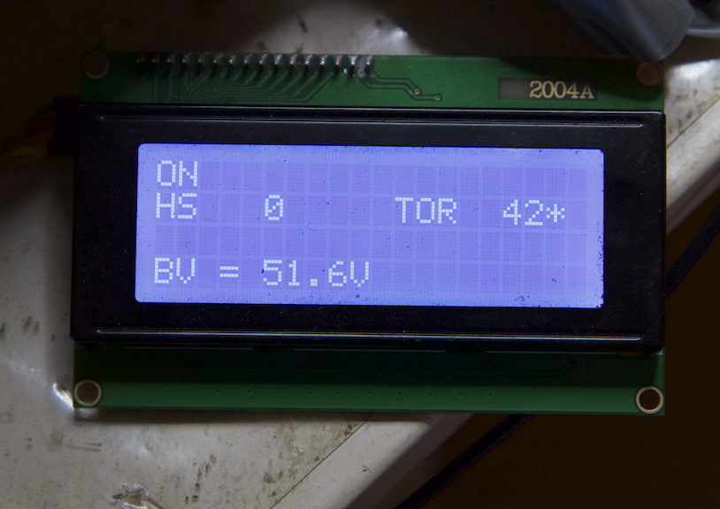 A bare bones display, just the data we need and nothing else. The two temperatures are in deg. C and the star means the fan is running. Output voltage is not shown, I did not need it so I did not design it in. The HS NTC is not connected so it shows zero. The picoverter will be just as useful without an LCD. The on-board LED shows if the inverter is running. The LED on the Nano will blink fast when the inverter was stopped due to over temp of either HS or toroid. It will blink slow if it's stopped due to under voltage. If it's OK, it wont blink at all. I probably will not need the LCD myself but it's here anyway for those who want it. wronger than a phone book full of wrong phone numbers |
||||
| poida Guru Joined: 02/02/2017 Location: AustraliaPosts: 1389 |
Nicks: the nanoverter feedback voltage is about 2.75V. This is referenced to the nano's ADC voltage reference and so for the picoverter I just built, it's 5.05V When the inverter is running, the closed loop control will ensure the feedback voltage is 2.75V or increase the output AC voltage to try and get it there. It's up to us to give it the 2.75V at our desired output AC voltage by whatever means are needed. The nanoverter & picoverter Vfb input circuit draws about 1.5mA so some of the smallest PCB type transformers might not be able to provide this current. (you can see where I got the 2.75V from if you look in the nano1 or picoverter code. somewhere I do a comparison of the feedback voltage sensed on ADC pin A0 with 0.55 0.55 x 5V = 2.75V) wronger than a phone book full of wrong phone numbers |
||||
| nickskethisniks Guru Joined: 17/10/2017 Location: BelgiumPosts: 416 |
It was late yesterday so was not thinking straight... I killed a few nano's, but reburning the bootloader and reloading the firmware solved the problem. Something to do with my self-made power supply (Chinese buck inverters) and buck regulators on the board. Replacing by the normal 7812 types solved that problem. I think there are spikes during the connecting/disconnecting of the power to the board, this is messing up the uC. I will just remove the nano first and will hook up the sense transformer to the 230VAC. Then I just measure the output on the nano input and trim it to 2.75V. Edited 2021-05-26 22:38 by nickskethisniks |
||||
disco4now Guru Joined: 18/12/2014 Location: AustraliaPosts: 844 |
copied from the 150V 45A MPPT - roll your own thread Latest F4 Latest H7 |
||||
| poida Guru Joined: 02/02/2017 Location: AustraliaPosts: 1389 |
what a dickhead,eh? Thanks Disco (and WG) wronger than a phone book full of wrong phone numbers |
||||
| nickskethisniks Guru Joined: 17/10/2017 Location: BelgiumPosts: 416 |
Yeah, sorry we are messing with your threads  . .Peter is it problem I poll the nano2 like 1 time/sec, or will it mess with the reliabililty . I want to poll for data to use on a webpage/ safe in a database. I know you did it a bit differently in the mppt code to make sure the code was not running slow. Something like this: switch (c) { case '^': // this probably used by myself only, to allow remote control of nanverter via the raspberry pi & USB serial spstr.setCharAt(0,' '); // remove ^, so as to allow conversion to int i = spstr.toInt(); // send ^nn<newline> if (i == 42) Serial.println("the answer to life, the universe and everything"); if (i == 10) oen = 0; // if (i == 11) oen = 1; // eg 13<newline> to obtain DC volts if (i == 12) { Serial.print(acv); Serial.print(","); Serial.print(dcv); Serial.print(","); Serial.print(aci); Serial.print(","); Serial.print(dci); Serial.print(","); Serial.print(hs_temp); Serial.print(","); Serial.print(tor_temp); Serial.println("*"); Edited 2021-06-01 06:08 by nickskethisniks |
||||
