Notice. New forum software under development. It's going to miss a few functions and look a bit ugly for a while, but I'm working on it full time now as the old forum was too unstable. Couple days, all good. If you notice any issues, please contact me.
Revlac Guru Joined: 31/12/2016 Location: AustraliaPosts: 961
Posted: 09:19am 01 May 2021
Copy link to clipboard
Print this post
First of all, Thanks Bruce for the opportunity to work on this inverter, The transformer is looking good. We have almost all the parts now, there may be a few additional things as the build progresses.
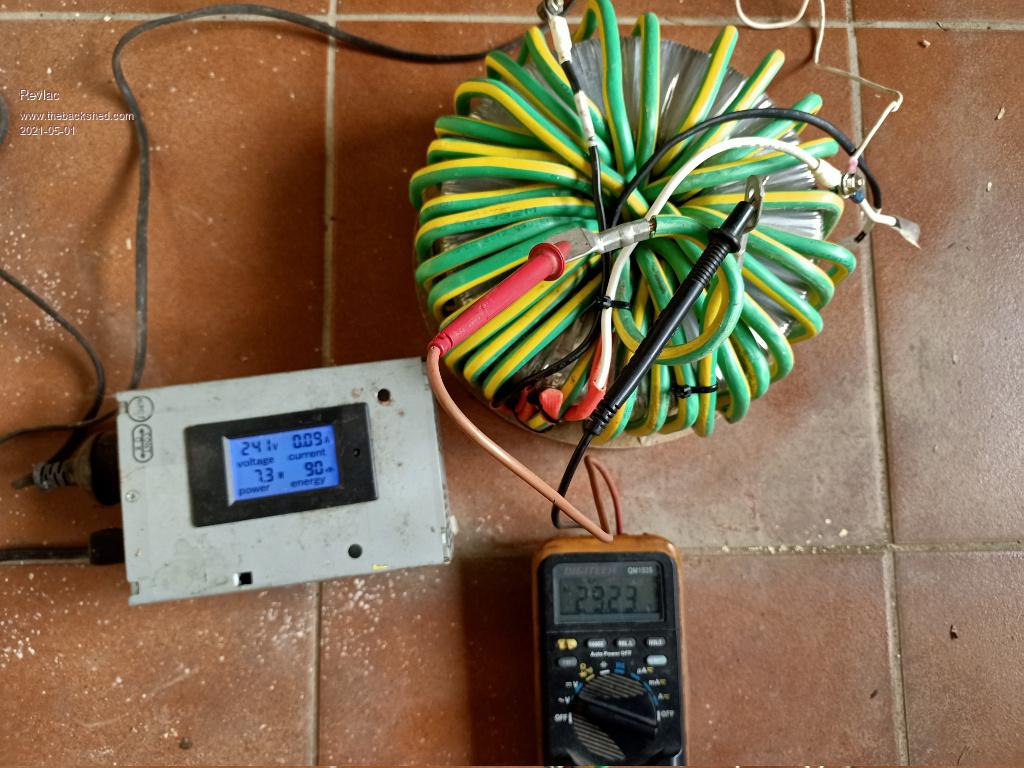
Tested the Toroidal transformer the other day using the light bulb as a soft start, then bypassed it with a switch. Results are good, 240Vac in and 29Vac out at about 7watts, so now I have some working numbers to go with, should use the same meters later as there is some variation in readings between meters.
I think Most of the builds here were 28v on the primary, if we need to we could take a turn off the primary and go with it.
Next job will be to test the transformer resonance, found the test circuit on the bench, but the wiring diagram is somewhere amongst the paperwork on the bench, clean the bench up and probably loose other things in the process, it happens.Cheers Aaron Off The Grid
Murphy's friend Guru Joined: 04/10/2019 Location: AustraliaPosts: 582
Posted: 09:33am 01 May 2021
Copy link to clipboard
Print this post
Hi Aaron, nice build, I see you were having fun fitting that last primary turn .
One thought, beware that little VCP energy meter. I had 2 of them blow unexpectedly until the penny dropped - mine were rated for only 260VAC. Not enough margin for our 230-240V inverters. I now make sure its a 300VAC rated meter when I buy another one on ebay.
Revlac Guru Joined: 31/12/2016 Location: AustraliaPosts: 961
Posted: 12:10pm 01 May 2021
Copy link to clipboard
Print this post
Hi, Have to make a correction there, this build is a joint effort and Bruce will do the final fit up of the inverter, it was Bruce, brucedownunder2 that (had all the fun) wound the toroidal transformer, that is some tough electrical mains wire by the looks of, really not flexible like the welding cable others have used, must have been tiresome working with that type of cable, I used 15mm X 2mm copper strap on the other transformer and I'm sure it was softer than this stuff.
Yes, Found out the other day about these little meters, with high voltage (400vac) and a horrible sine wave from a generator going mad, the resistor/cap under the LCD was getting really hot melting plastic and changing the LCD colour.
I have 4 of them AC and DC versions on the other 2 inverters, have not given any trouble yet, they do not measure over there rated current, motor starts etc. If they give any trouble, will try something else, the inverter voltage output has been quite stable.
Thanks Murph, I will check the voltage rating, if they have a label on them. Cheers Aaron Off The Grid
brucedownunder2 Guru Joined: 14/09/2005 Location: AustraliaPosts: 1548
Posted: 12:28pm 01 May 2021
Copy link to clipboard
Print this post
OK, first , a big thanks to my mate Aaron. When I was in hospital,with nearly 200 stitches holding my head on, he suggested I rest up a bit while he finished off my inverter.
Going back to my winding days, that 20mm green earthing building wire was a shocker to wind. She,s hard enough,but after a few bad bends and then getting it OK , it,s as stiff as hell to bend with my 76 year old fingers.
I,ve sort of bashed together the inverter housing out of an old Ericsson rectifier I scavenged out of my works industrial bin ,,some years back. A bit of cutting fan holes and cable entry holes ,a coat of paint , and it fits the bill. Aaron is the taskmaster when it comes to getting all the right coloured leds working ,so hopefully he,ll have a easy journey.
I,ve scavenged lots of different heat sinks over time ,so he,ll chop some up and fit them. The choke should be OK, as I had that working in an old Powerstar W7 6KW 48 volt unit I put together in those way back days.
I,m looking forward to seeing the finish, using my modified ups at present to run lights and workshop tools,. It,s been great,just disconnected the alarm and it runs all day ,no problems.
Nice to have friends , like Aaron ,and his Dad,,Hello Ron. They are a good team ,with the best farmyard of good home built stuff I,ve seen.
BruceBushboy
Revlac Guru Joined: 31/12/2016 Location: AustraliaPosts: 961
Posted: 12:35pm 02 May 2021
Copy link to clipboard
Print this post
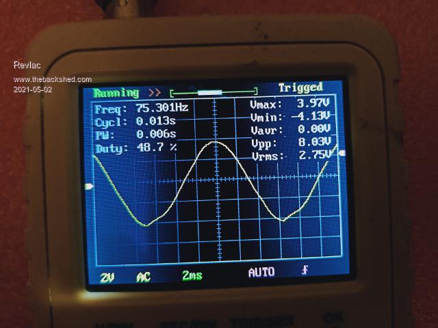
Happy to work on this Bruce, always learning. Been a busy day today, Did the resonance test at 75hz, to check the capacitance needed on the transformer primary. The first picture is the wave on the primary without any capacitor connected.
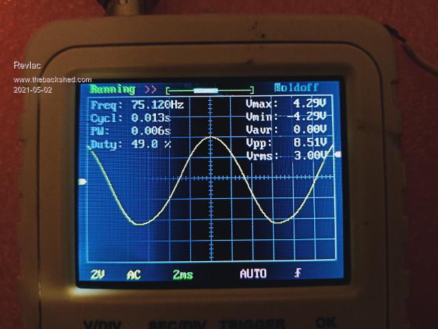
The next is with a 1uf capacitor, there is an increase in peak voltage compared to the previous test.
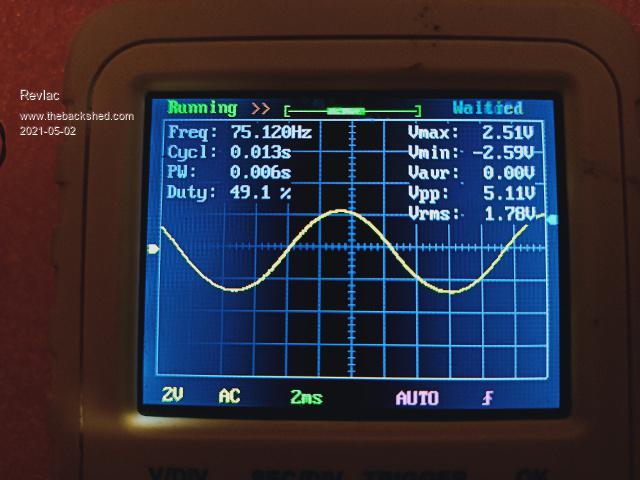
This one is with a 3.5uf capacitor connected, quite a large drop in peak voltage. Seems to be a lot less capacitance than expected so its always good to check this as all builds are different, I had a guess of about 3uf, that looks to be way off, I will try this again later to see it I did anything wrong, the frequency generator is getting a bit flaky, so might be time to make a new one.Cheers Aaron Off The Grid
Revlac Guru Joined: 31/12/2016 Location: AustraliaPosts: 961
Posted: 08:58am 05 May 2021
Copy link to clipboard
Print this post
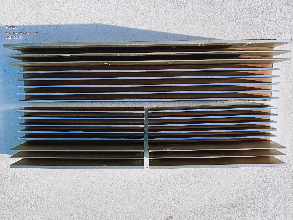
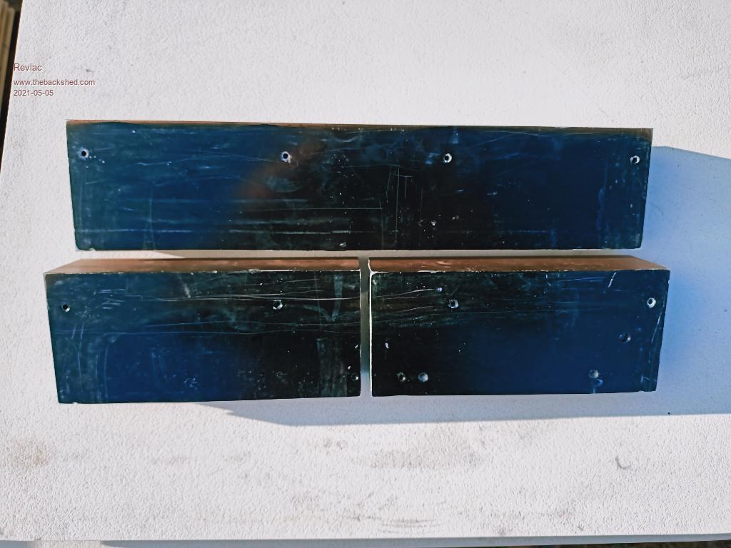
Working on the heat sink, not difficult to cut the large heat sink into 3 parts and trim down a few fins. I used to build Aluminium boats, most aluminium cutting was done with multicutter, tungsten tip saw blade that has different teeth and grade of tungsten than your average wood saw blade, we also had a large metal cutting blade in the drop saw, very expensive and always use some sort of lubrication to keep the blade from grabbing, also prevent any buildup between the teeth that can break the teeth off.. The most we cut in one day was about a ton, That was a lot of aluminium shavings to sweep up at the end of the day.
You can also use those thin .9 or 1mm cutoff wheels, with plenty of lubrication (often) they will also do an exceptional job on small one off projects.
There is some existing holes in the heat sink, if they end up under where the mosfet mounts on, I think it would be good practice to clean the hole out and plug it up with some alloy rod or plug and level it off flush with the heat sink.
Next is the 20 or so holes to drill and tap. Cheers Aaron Off The Grid
brucedownunder2 Guru Joined: 14/09/2005 Location: AustraliaPosts: 1548
Posted: 09:19am 05 May 2021
Copy link to clipboard
Print this post
Hi Aaron , Looks like you found a job to do out of the rain ,today?.
I have a tungsten tooth blade in my dropsaw for copper and aluminium,,,I,ve been using a small squirt of WD 40 for the lib. I used to use Trefolex , can,t spell that one,. Anyhow, what do you guys use?.
Building a extension to my equipment wall,was getting congested, so more area to mount stuff.
You all have fun , thanks toAaron.
BruceBushboy
Revlac Guru Joined: 31/12/2016 Location: AustraliaPosts: 961
Posted: 12:48pm 05 May 2021
Copy link to clipboard
Print this post
Did get some good rain over night and today, was outside the shed and started cutting these heat sinks, perfect opportunity for it to rain Heavy about half way through, and it did...
For cutting lubrication at work, we used some sort of wax on the Bandsaw and Dropsaw also used WD40 on the Dropsaw if we Didn't want too much mess, had to clean everything that was cut to achieve a good weld on aluminium.
For this heat sink, used some lanotec lanolin spray, it held on to the cutting wheel a little longer, also good on the flapdisc variable speed angle grinder sander, gives a much better finnish...Cheers Aaron Off The Grid
Revlac Guru Joined: 31/12/2016 Location: AustraliaPosts: 961
Posted: 08:38am 17 May 2021
Copy link to clipboard
Print this post
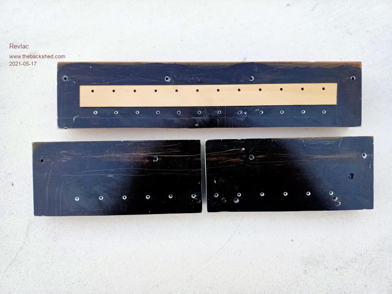
Made up a drill template and laser cut it into some thin plywood, not absolutely perfect but it worked ok and was helpful, Easier than measuring and marking each hole. All drilled now but have only taped a few so far, might not need anymore than 4 fets per leg, should be enough power. I think what I should have done was drill and tap some bigger holes and bolt a plate across the front of the mosfets to hold them down, same as have done before, still could do that if we need to.
Cheers Aaron Off The Grid
Revlac Guru Joined: 31/12/2016 Location: AustraliaPosts: 961
Posted: 09:58am 17 May 2021
Copy link to clipboard
Print this post
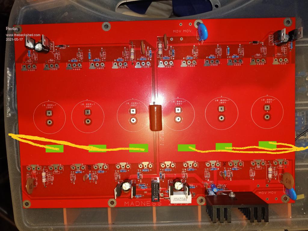
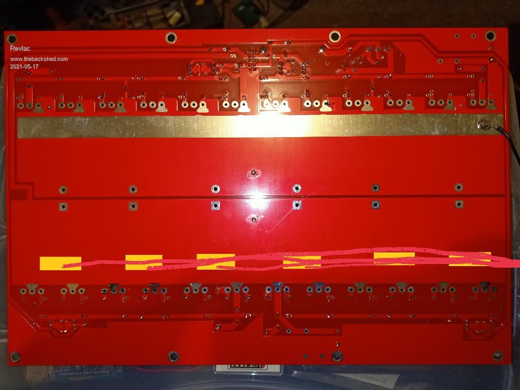
The 2 previous inverter builds have live heat sinks and the cables from the transformer and choke connect to the heat sinks, and have been running ok, weather that will give any trouble down the track I don't know. Using the back of the mosfets as a connection is probably not the most ideal way to run parallel mosfets, this time round we might try to run multiple wires attached to the power board instead of just using the heat sinks, or connect both, perhaps a stud bolted through the heat sink to make it easy to connect. Just a thought while tapping the small threads, Hope I don't brake the damn tap before the job is done.
I have drawn in a few wires and solder pads in the approximate area were the wires might go, looks a bit crude but hopefully it makes sense.
The negative is already done this way.
Cheers Aaron Off The Grid
brucedownunder2 Guru Joined: 14/09/2005 Location: AustraliaPosts: 1548
Posted: 11:05pm 17 May 2021
Copy link to clipboard
Print this post
Hi Aaron.
Looks fine to me . I'm a bit new to solder "pads" , I'll try my hand at a sample piece of PCB first ?. I think I'll have to experiment with a couple different solder iron nibs ,have an assortment ,that I've never used. Plus ,I'll be asking you for solder and flux advice.
The tapping , I mostly do mine by hand ,and Yes, I do have that "Lanotek" Lanolene anti-siege lubricant for tapping.
Ribbon cable would be tidy for that fet pad connection ??.
OK, me, back to cutting grass today,, my helper has sold up and left ,I suppose at 78 he should be "hanging up his boots" .. I'm 76 and still looking after my lot, but for how long ????.
Cheers,
BruceBushboy
wiseguy Guru Joined: 21/06/2018 Location: AustraliaPosts: 995
Posted: 12:24am 18 May 2021
Copy link to clipboard
Print this post
Hi Aaron, thanks for posting the pictures. If you go for the multi wires approach, it should achieve what you want - try to keep the wire groups the same lengths. In your picture you only show the positive and 2 x choke connections what were you planning with the negative supply connection?
After having a bit closer look at the MAD board it was a pretty good effort, (despite my aversion to using ribbon cables). The 2 x Gate drives for the upper sides should have been sent up through the centre divide instead of the longer treck around outside of the pcb (the bootstrap power trace could have gone around the outside - length of that trace is relatively unimportant) and the 2 buffer stages located more centrally similarly to the low side buffers PCB rather than the outsides, it all helps to reduce the length of the switching traces, I've not examined the board close up so there may be other constructive criticisms but nothing jumps out at first glance.
It appears you are only going to load the central 4 FETs first (a lot of gate resistors missing......) for a trial ?
When tapping into aluminium, if M3, depending on TAP type I do about a half turn and back it off to feel the swarf break - if its still not "totally free" back off a bit further before adding the next half turn etc & I am very liberal with the WD40. Nothing worse than tapping 16 holes and the tap breaks off - in the 16th hole and is next to impossible to remove and the last 2+ hours are then wasted.....If at first you dont succeed, I suggest you avoid sky diving.... Cheers Mike
Revlac Guru Joined: 31/12/2016 Location: AustraliaPosts: 961
Posted: 10:18am 18 May 2021
Copy link to clipboard
Print this post
Thanks for the input Mike, I did wonder about the wire length when doing it this way, The multi wire approach, it makes sense to have them the same length, will try to do that, if I can make it neat enough and not block any airflow between the heatsinks etc. Depending on the size of wire I can find and amount of wires needed I Would like to end up with a total of at least 16mm2
The negative would be done the same way, I had a photo (lost it) of the other inverter with I think 4 (heavy gauge) wires soldered onto the plaited strip, each was a different length and all ended in a single crimped terminal hanging out from the end of the board about 200mm or so, Its working well. This time I would prefer no wires hanging off the board, connections (except negative) to either go to the heat sinks, or might be better to have all them terminate on some base or mounting under the entire power board....something to think about.
Its a good working board and I thank Gary and others for making it possible for the rest of us to get something started and use, very pleased with the way it works, I'm always interested in other ideas and ways things can be done.
Will do the usual test with 1 fet per leg first then just do 4 per leg and leave the rest as an option, I noticed last time the power consumption (unless its my imagination) change a little with the amount of fets driven, will see if that's happens this time round.
The M3 tap I'm using, think its not a good quality one, get about a 3rd of a turn then back off or its a bit tight, I once spend a day at Bournedrill in the machine shop, one of the operators there was using a machine to tap threads (lots of em in steel) he said its best to use spiral fluted taps for the job he was doing, clears the swarf better. I'm sure there is a better quality tap here somewhere I think the Old Man has it hidden some place in case I brake it.
Easy to brake that's for sure, only need a long sleeve shirt to catch the T handle or even swat some annoying fly...much swearing can follow. I just pick a time when every thing calm and steady to do it, just tap 1 in each heat sink and rotate through each heat sink.Cheers Aaron Off The Grid
poida Guru Joined: 02/02/2017 Location: AustraliaPosts: 1388
Posted: 11:38am 18 May 2021
Copy link to clipboard
Print this post
I agree about WD40 or other lube. Kerosine is good when cutting Aluminium too. WD40 seems to be good for this tho.
I have done a large no. of M3 tapped threads with the same tap. I always try to drill 90 deg/perpendicular into the work. And then set the tap at same 90 deg. Most threads do not need backing off 1/2 turn as you go. Usually misaligned taps with the holes need the 1/2 turn back off. This is just my experience.
I found in the past it useful to make a small guide out of rectangular section steel tube with the drill holes done by a drill press to ensure good 90 deg perpendicular alignment. This will give you good holes every time when you do it by hand.
Then use similar guide for tapping. Maybe need a new one or you could use the drill guide. see how you go.wronger than a phone book full of wrong phone numbers
poida Guru Joined: 02/02/2017 Location: AustraliaPosts: 1388
Posted: 11:54am 18 May 2021
Copy link to clipboard
Print this post
I agree with the assessment. It's not optimal but it works pretty well, at least good enough for the girls I go out with around here (AvE reference)
From the experience of using these boards for years, I am happy to continue using these boards, now slightly modified by me for a few more years.
Board blowups now are a thing of the past for me, thankfully. When they blow usually a bit of a PCB trace is taken off to The Maker as well. I found having the FETs soldered into the board with 15mm pin lengths to be very good. It lets you mount the heatsink further up from the caps. It gives some separation from PCB and FET when they blow. It lets you get the side cutters into them to cut them out when it blows. It makes it easier to desolder the longer pin leads compared with short leads. The HY4008 pins are rated at 70 Amps continuous so they usually do not fail. The failures usually are within the TO-247 package and or the PCB track. I kind of want a weak spot that is the long pins rather than having the weak spot being the PCB. But all this is my opinion.
Now I have gerber files for the power board and can get them for $25 it no longer seems such a big deal when they blow. Just rip out the big caps and make a new one with all new passives, diodes, transistors etc and using the salvaged caps.wronger than a phone book full of wrong phone numbers
nickskethisniks Guru Joined: 17/10/2017 Location: BelgiumPosts: 411
Posted: 01:54pm 18 May 2021
Copy link to clipboard
Print this post
I hated to tap those M3 threads until I did the drilling on a drill press, it's literally half the work, but's it's so important to drill at 90 deg. It's important the mosfets make perfect contact with the surface. I do the M3 tapping by hand, just need to be patience and use the right drill!
Revlac Guru Joined: 31/12/2016 Location: AustraliaPosts: 961
Posted: 12:18pm 04 Jun 2021
Copy link to clipboard
Print this post
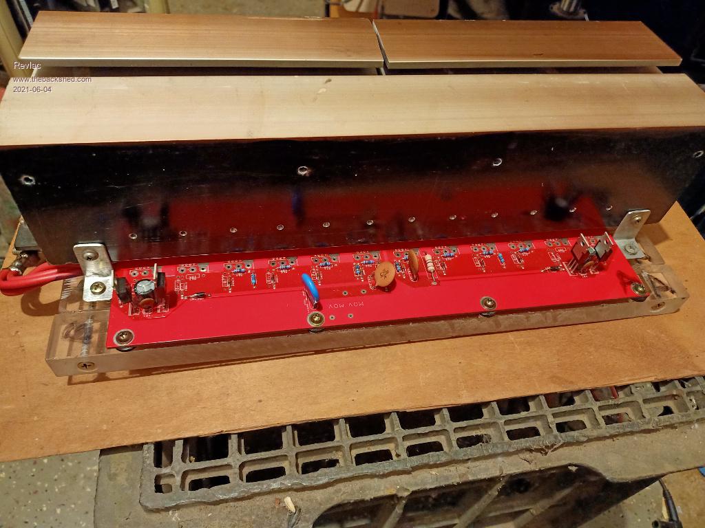
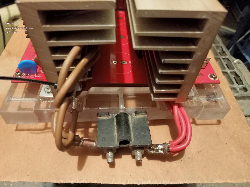
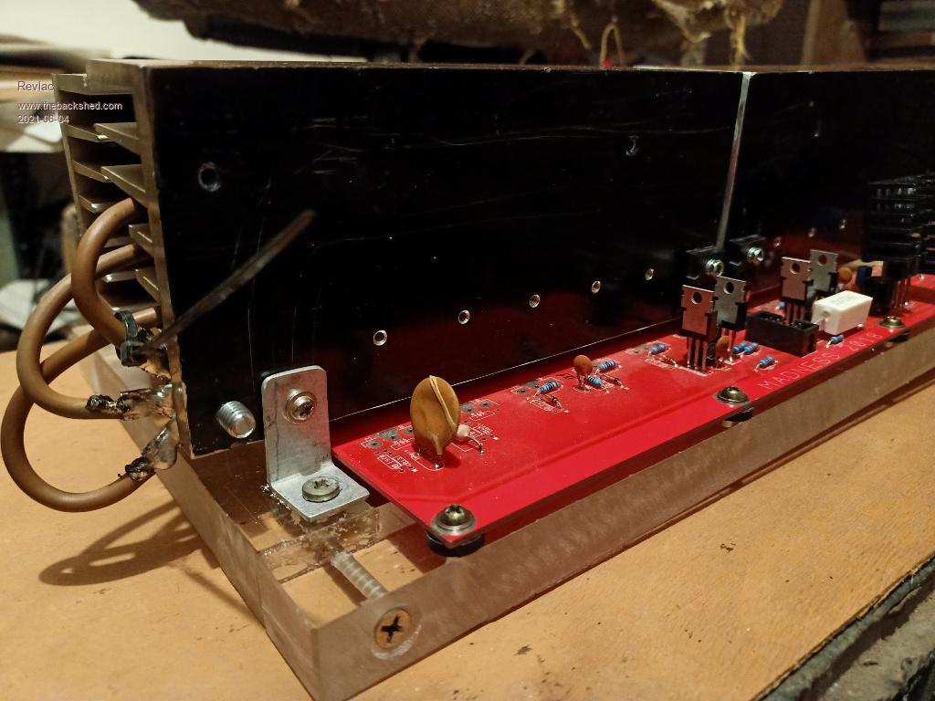
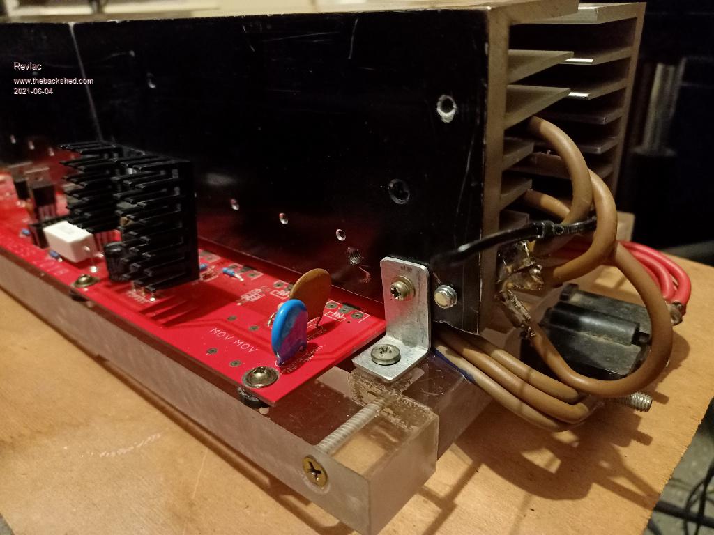
A little more progress when time permits. The wires are now connected to the PCB and are the same length, they are attached to the heat sink with a bolt, and can be bolted on the front of the heat sink as another option, the transformer and choke leads can go onto those bolts. Heat sinks have a small brackets at each end to help steady and strengthen it all up. All mounted on some strong perspex frame that can be mounted easily. The mosfets are not in yet, there is some length for the mosfet legs, I could add a little more but will see how it looks later, still some holes to plug up on the heat sink, I also plan on going over the face of the heat sink with the orbital sander when ready to place the mosfets in.
Still more to go. As usual no two builds will be the same.Cheers Aaron Off The Grid
brucedownunder2 Guru Joined: 14/09/2005 Location: AustraliaPosts: 1548
Posted: 03:22am 05 Jun 2021
Copy link to clipboard
Print this post
Hi Crew.
It's coming along nicely, thanks to Aaron .
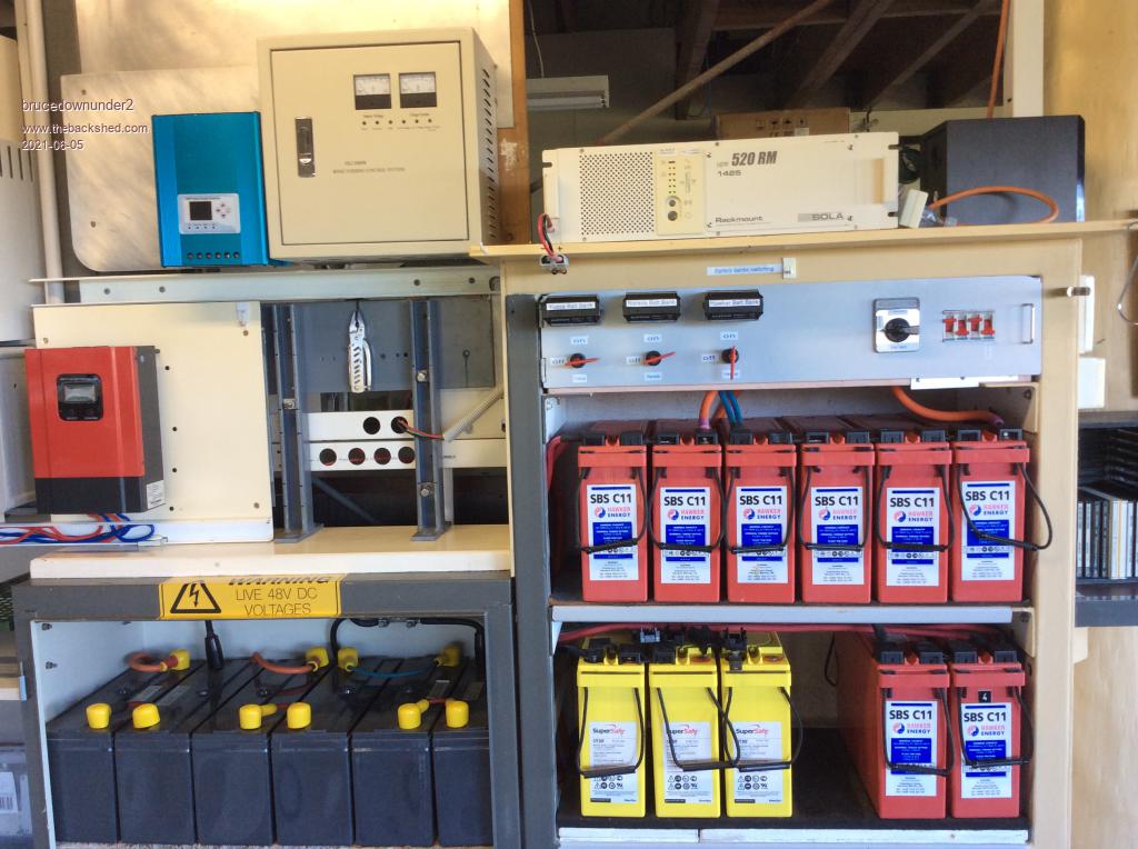
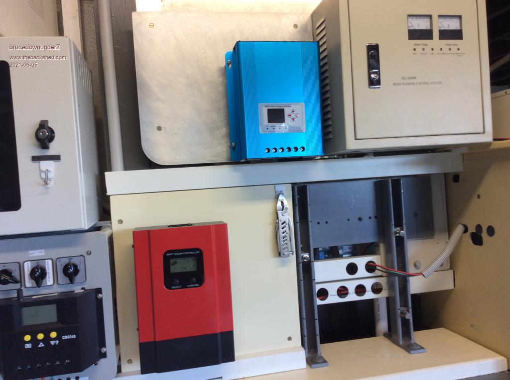
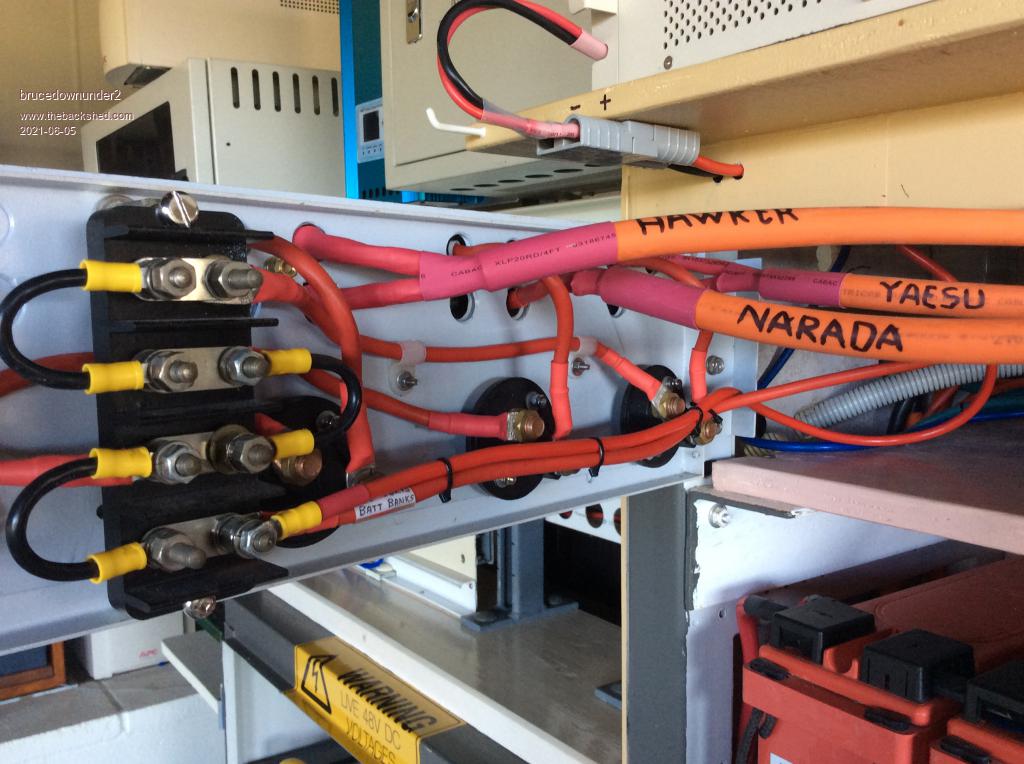
I've been working on my end ,sorting out some refinements to switching between batteries and controllers, more or less for redundancy if parts fail and the ease of charging more or less in a battery bank.
I'm interested in installing a fork-lift type battery bank in the future, with the idea of being able to stand-alone off home batteries.
Here's a shot of the control panel I've finished, apart from the rotary switch which will be operational soon.
Have a nice day ,
BruceBushboy
Revlac Guru Joined: 31/12/2016 Location: AustraliaPosts: 961
Posted: 08:25am 06 Jun 2021
Copy link to clipboard
Print this post
Looking nice and neat Bruce,
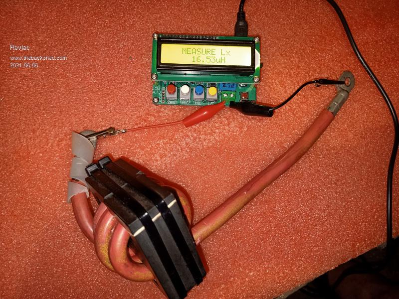
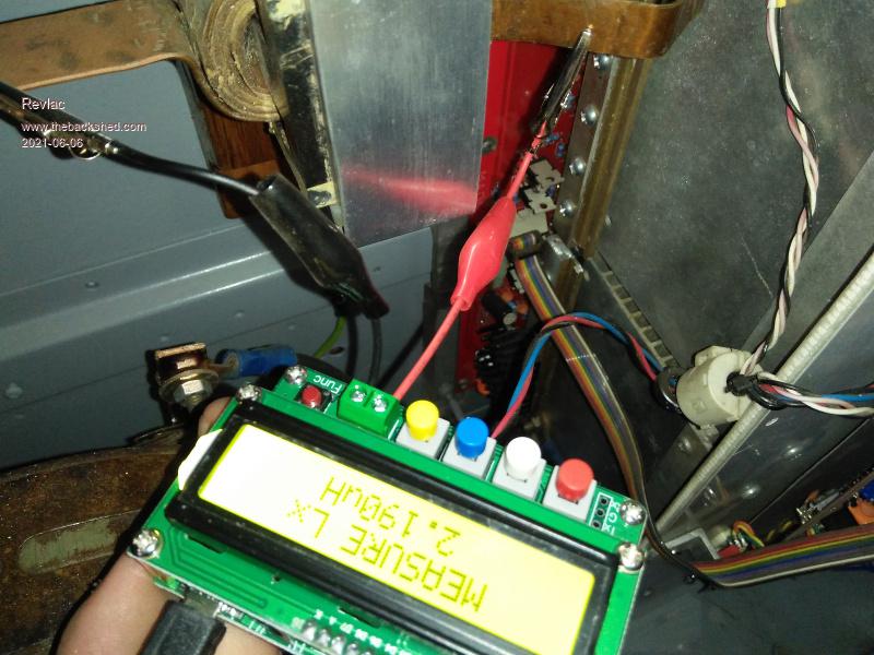
Measured the choke that Bruce has wound up for this inverter, and the Lc meter reads 16.5uH, this looks a bit low compared to others, unless I'm mistaken. Also I think it will need a small spacer inserted where the ferrite butt's together, for this EE choke, without any gap its likely going to squeal or something.
I made up a double EE choke up for my other inverter (Details elsewhere), have since tested that with the Lc Meter and that come to 2.2uH, so will remove that as its not doing much.
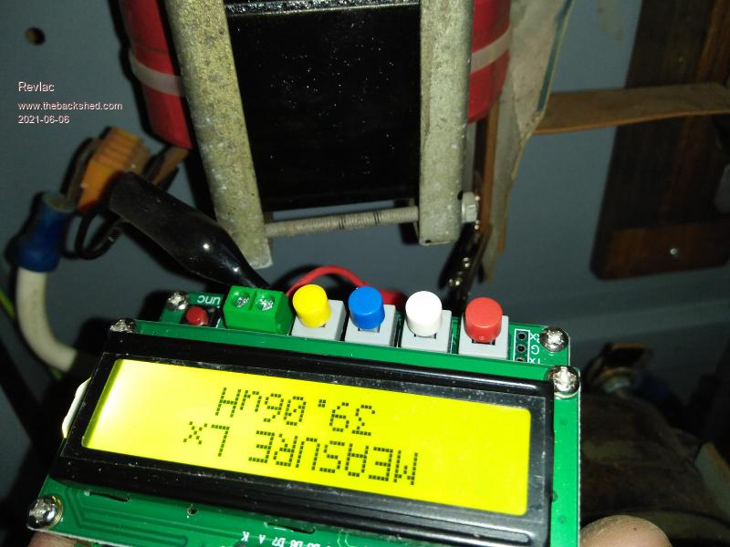
The other large choke I made up for my other inverter (again Details elsewhere) tested 39uH and that inverter is running well with it, Roughly 90% efficient at 2000w.
Its the same dimensions as a pair of aerosharp chokes but made of thin silicon steel strip same as the toroids, I think we may have to make one of those, from some scrounged parts. Edited 2021-06-06 18:36 by RevlacCheers Aaron Off The Grid
johnmc Senior Member Joined: 21/01/2011 Location: AustraliaPosts: 282
Posted: 08:56am 06 Jun 2021
Copy link to clipboard
Print this post
Bruce looking good.
But, make sure that the battery power leads to the inverter, are the only leads
that are connected to the inverter inputs.
ie (only battery to inverter, other wise sometimes magic smoke).


 .
.