
|
|
Forum Index : Electronics : Bruce Inverter build
| Author | Message | ||||
| Murphy's friend Guru Joined: 04/10/2019 Location: AustraliaPosts: 583 |
Aaron, regarding chokes that work, have a troll through the topic "recycling those aerosharp chokes" by tinker some time back choke Doing it that way >does< work. Max copper & max inductance for given space available. |
||||
Revlac Guru Joined: 31/12/2016 Location: AustraliaPosts: 961 |
recycling those Aerosharp chokesSome very nice work there,  one way I would like to have done this is to use copper strap (with correct suitable dimensions) and just wind it up, however that copper is probably the most expensive to buy if one Doesn't have it on hand, I used aluminium strap last time, It appears to work well, one way I see it if it generates some heat over the ambient temperature it must be working, if its cold it not doing nothing, perhaps. one way I would like to have done this is to use copper strap (with correct suitable dimensions) and just wind it up, however that copper is probably the most expensive to buy if one Doesn't have it on hand, I used aluminium strap last time, It appears to work well, one way I see it if it generates some heat over the ambient temperature it must be working, if its cold it not doing nothing, perhaps.  The 3D printed former looks like something I could have ago at, Its not hard to find plenty of small wire. Cheers Aaron Off The Grid |
||||
| brucedownunder2 Guru Joined: 14/09/2005 Location: AustraliaPosts: 1548 |
I seem to remember on my last powerstar 7 mod that I built a choke(the one I gave you ,Aaron) ,sort of buzzed a bit when I connected a hair dryer to it-just for a second, then no buzz. I also have here a whopping big transformer ,maybe from a salt water chlorinator , sort of 8mm X 3mm rectangular winding. (copper). Aaron, you might like this material to play with.?. another thought I had was if I am to use the inverter for a predetermined current, say, 4-5 Kw then the choke might be able to be constructed with lighter gauge wire ?. (but maybe what we have is sufficient)?. Blowing a gale here, and very cold, for us banana benders anyhow. Bruce Bushboy |
||||
| Murphy's friend Guru Joined: 04/10/2019 Location: AustraliaPosts: 583 |
Copper strap, you need around 0.5mm thickness at least to get a useful sq/mm rating but thicker than 1mm would be hard to wind. You'll also need insulation between the turns. Then you have the problem how to route the start to the coil outside. Then you have to make a suitable connection for a big solder lug... This does not look easy to me and I doubt you'll get 18 turns onto a dual big recycled core. I use recycled enameled copper wire bits, wound two in hand one full layer. Epoxied this and wound, on the next day, another two in hand layer. Repeat until the temporary core former was full, 8 layers = ~41mm sq of 1.8mm wire. The lathe pic on the end of the linked page shows how, I think there are other pics elsewhere for that method. Much easier that way and no fancy former at all is required, the epoxied wires made that redundant. From all my testing over the 14 or so years on this forum I found the original, as oztules suggested, ferrite choke cores work well with the Powerjack inverter. Tried the silicon steel type with that but it was not so good. For all the other inverters I built right up to the latest opto isolated nano type the silicon steel choke cores were far superior to the ferrite type. IMO  . . |
||||
| Revlac Guru Joined: 31/12/2016 Location: AustraliaPosts: 961 |
Bruce, if we go with the ferrite core, or at least try it, I can slip a plastic shim in between, just to make it sound happy. Or we will try, or make up another choke, see what we can find to work with. The big transformer sounds nice. Getting a bit cool and breezy here, not many branches blown down yet, spent yesterday afternoon tying everything down expecting some wild weather. Cheers Aaron Off The Grid |
||||
| Revlac Guru Joined: 31/12/2016 Location: AustraliaPosts: 961 |
Murph, Using copper strip for a large choke is fairly standard, seen many of the done 1mm X 100mm wide with ends for the lugs to bolt on to, the last one I did was with aluminium, was quite easy once worked out, 1mm thick aluminium and a total of 70mm wide 3.1m long and 13 turns. Have a photo somewhere. 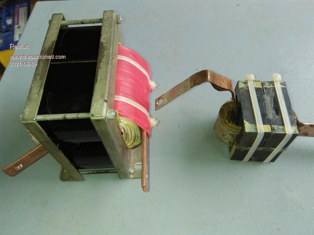 Found it. However If I look around I might find some enameled wire of suitable size and try your method. Haven't done one like this so why have ago, Worthy challenge I think.  Edited 2021-06-09 21:48 by Revlac Cheers Aaron Off The Grid |
||||
| Warpspeed Guru Joined: 09/08/2007 Location: AustraliaPosts: 4406 |
Its an excellent method if you can arrange it so the number of turns required fits exactly into one layer, and that often works out perfectly. The copper foil/strip way works very well too, but it needs to be thin and flexible. Its also possible to wind on several thin foils together without insulation between. That way, you keep the flexibility but can have a pretty thick layer per turn. Beware of shorted turns at the edges, the foil layer needs to be kept considerably narrower than the insulation layer between turns. Cheers, ĀTony. |
||||
| Revlac Guru Joined: 31/12/2016 Location: AustraliaPosts: 961 |
Did a test run the other day, unwound one turn on the transformer primary and placed some shim materiel in side the choke (runs silent), 1 fet per leg, no capacitors and a large series resistor in case of you know what... this was its first test run and it fired up ok. 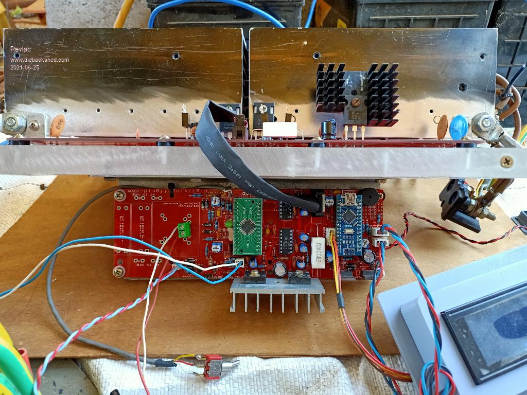 Found some issues, not unexpected, had some serious over voltage on the output, easy fix just changed the value of the feedback resistor. the other problem was one of the DSB temperature sensor's was not working, I know it was working before Took a photo of it, turns out to be a bad solder joint just below the 3 pin connector on the pcb, easy fix. Second test run, much better but the voltage is still a bit high and run out of adjustment, output is 250vac.. 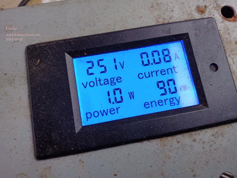 will change to a lower value resistor, the little transformer is 13vac at 240v last I checked The toroidal transformer has some buzz sound to it but not bad. 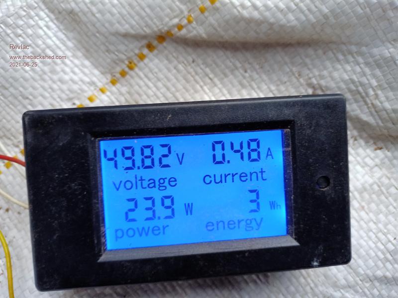 The power consummation is just on 24w, thats about what I was expecting at this stage, it might change a little when its all completed. 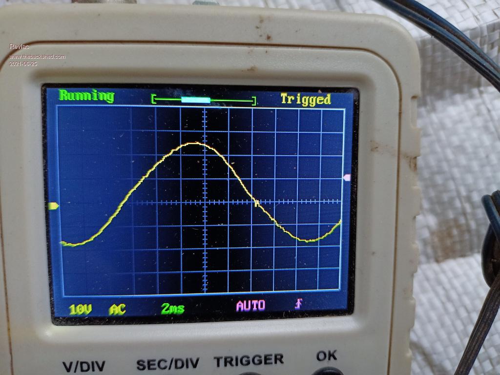 Now there is a little kick in the sinewave at zero crossing on the scope, we can do better, I fairly sure this can be fixed with a bit better choke. Anyway I have to change that resistor and try again, overall its looking pretty good. Edited 2021-06-25 21:47 by Revlac Cheers Aaron Off The Grid |
||||
| Warpspeed Guru Joined: 09/08/2007 Location: AustraliaPosts: 4406 |
Excellent progress Aaron. Cheers, ĀTony. |
||||
| Revlac Guru Joined: 31/12/2016 Location: AustraliaPosts: 961 |
Thanks Tony, I have learned a lot here, even better when it's put this into practice and it works, especially when we can work with our own parts (often different) to achieve the result in witch we aimed for. This is the first inverter I have worked on that uses a toroidal transformer, I will compare the results with the C Core transformer, just for curiosity. Cheers Aaron Off The Grid |
||||
| Revlac Guru Joined: 31/12/2016 Location: AustraliaPosts: 961 |
After placing one capacitor on the power board with one fet per leg, it helped clear up noise on the DC bus, the idle current reduced to 21w with the output at 235vac, I then added the rest of the fets for a total of 4 fets per leg and associated gate drive resistors, the idle current is 24w, so the rest of the fets added another 3 watts, just to show where the watts go.... All 6 of the 10000uf capacitors are in place now, and Bruce will be working on the fit up. Cheers Aaron Off The Grid |
||||
| Warpspeed Guru Joined: 09/08/2007 Location: AustraliaPosts: 4406 |
Great stuff. Thinking about it, that little kink in the waveform (if its still there) might be caused by primary to secondary capacitance in your transformer. Anyhow, its nothing to be too concerned about. The off grid waveform here looks like crap, typically around 5% measured distortion and everything still works perfectly well off that. Cheers, ĀTony. |
||||
| Revlac Guru Joined: 31/12/2016 Location: AustraliaPosts: 961 |
The little kink is still there, The capacitance between the primary and secondary winding, could that be caused by the gap on the outside between the primary and secondary winding? Or something else. We might experiment a little later to see if anything changes. I agree, most of the inverter waveforms look better than generators that I have seen, I would like to see what some of the Stamford generators look like, when I get one going. Cheers Aaron Off The Grid |
||||
| Revlac Guru Joined: 31/12/2016 Location: AustraliaPosts: 961 |
Thanks Bruce, for dropping these chokes in the other day, will see if we can make something work from them. 2 small chokes and 2 larger one's, the larger type appear to be about the same as we would used for these home built inverters. The wire on the Big chokes is 3 mm diameter, the choke on the far right looks interesting, the winding is joined in the centre as expected, now that could be cut and run them parallel, that would be 2 in hand 44 turns (Roughly), at the opposite end we could cut the winding in half again, that could be paralleled and give us 4 in hand of 22 turns, all 3mm wire. I tried to test with a meter and it was around 400uh, but as no wires were cut the readings could be way off, But one like this might be suitable for a Mppt charger if done this way. As these are for the inverter.....there is going to be some rewinding to do, will use gloves.....I can see that flake stuff waiting there to get stuck into my fingers. 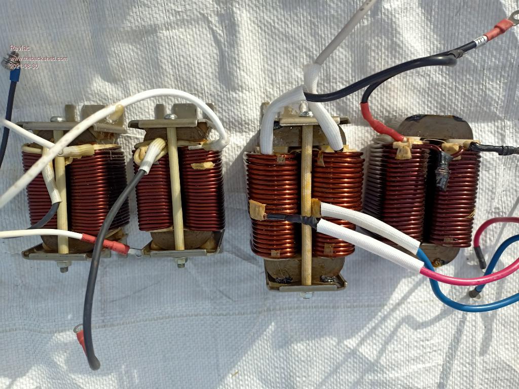 Cheers Aaron Off The Grid |
||||
| Murphy's friend Guru Joined: 04/10/2019 Location: AustraliaPosts: 583 |
Aaron, these are the choke types I re wound for my inverters. If you are unfamiliar with them, heat the nut first before unscrewing, this lets you re use the bolts with a healthy thread. Hold the choke in a gloved hand and hit the U core sticking out on one side with a soft hammer. After a few hits the core half slides out and you can push out the other. Note the two halves have white paint marks so you can assemble them the same way oriented later. I have re used the wire, its a bit of a job to straighten it though. Best to glue the halves from two original chokes together so they form a matching W and M, this gives you a bigger diameter coil for re winding. |
||||
| Revlac Guru Joined: 31/12/2016 Location: AustraliaPosts: 961 |
Thanks for the Tips Murph, Yeah I found the bolts were well stuck and tight, only did one, So will try the rest of them with one of those little gas torches. That seems to be the practice, the transformer on my inverter build also had white paint marks for correct orientation. The plan is to reuse the wire if possible the large ones should be ok if they come apart the way you did them, the small chokes have a lot more enamel coating on them, I did get a ferrite choke apart by using thinners or acetone fumes and letting it soak for a bit, I don't remember if it had any effect on the baked enamel, will see how it comes apart first, when time permits. Been reading through your other topic....very inspiring. Also, I did attempt to make a choke from an ordinary square transformer, cut the top off it to make it into EI with adjustable gap, wound up it measured about 40uH I think, still not tried it but I assume it would need to have a much larger cross section than these to achieve the same result, thats if it would do the job of filtering the frequency. Anyway will work on these for now. Edited 2021-08-31 22:48 by Revlac Cheers Aaron Off The Grid |
||||
| Revlac Guru Joined: 31/12/2016 Location: AustraliaPosts: 961 |
These were stuck together quite well, Got an empty 4l paint tin and put the 2 chokes in that with a small amount of thinners, left it to do it's thing over night. This softened up all enamel and other stuff and made it much easier to take apart, the wire looks ok so far. 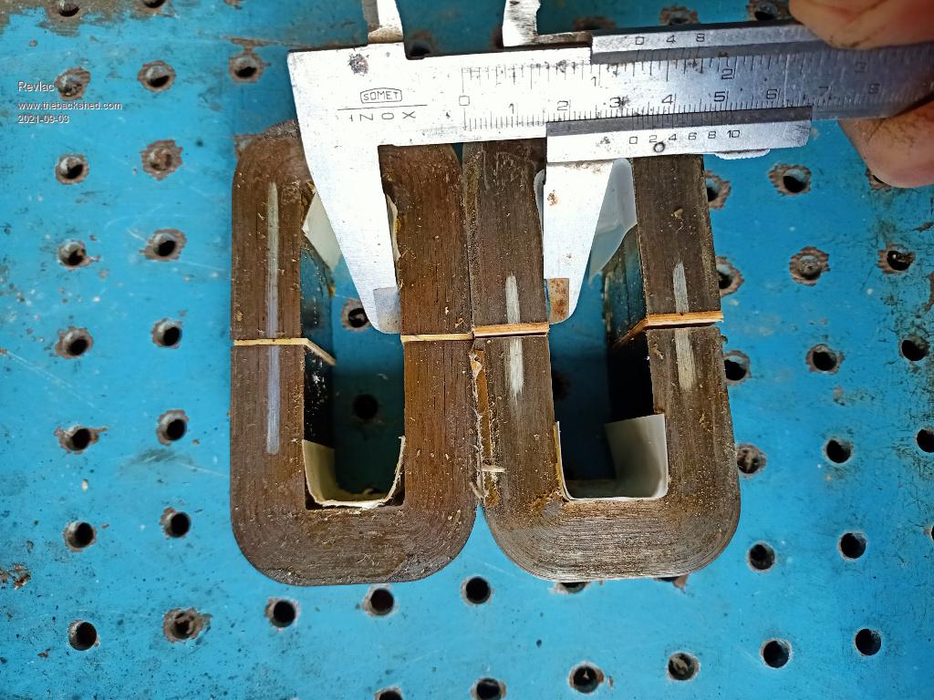 These are not exactly the same, but should still do the job, one is 45mm strip width, the other is 40mm strip with, will just put a little ship each side. In case anyone wants to know what size the spacer is between the core halves, its about 1mm to 1.1mm, calipers are old and a little worn. Cheers Aaron Off The Grid |
||||
| Warpspeed Guru Joined: 09/08/2007 Location: AustraliaPosts: 4406 |
Those look like the exact same cores Mark used in his choke. As I remember, the slots were 20mm wide and 70mm long, and his gap was also 1.1mm Mark fitted 12 turns of 20mm ^square wire (10mm outside diameter) and ended up with about 170uH and a saturation current of around 130 amps. Cheers, ĀTony. |
||||
| Revlac Guru Joined: 31/12/2016 Location: AustraliaPosts: 961 |
The original choke mounting brackets looked good enough to reuse, so cut one end back and welded them together, IT will work. Used to some scrap wire to test with, at first the tester reads 77uH, left it sit for a minuet and it settled to 67uH at 429372Hz, This is with 10 turns. 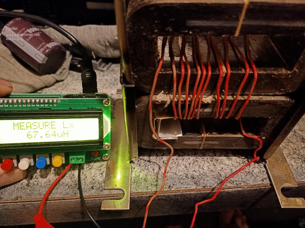 The reason For 10 turns, this 3mm wire with 10 turns 2 in hand would be about 60mm and the window height of 70mm would give some wriggle room for the not so straight wire. Should get 3 or 4 layers this way, This is the first option so far, that works with the wire on hand. I might try 12 turns and see what number I get, think it would be less than 170uH, one core being a little smaller. Cheers Aaron Off The Grid |
||||
| Warpspeed Guru Joined: 09/08/2007 Location: AustraliaPosts: 4406 |
One pair of cores looks to have a slightly larger air gap than the other ? Two extra turns will make a huge difference, its turns squared, so going from ten to twelve turns increases the inductance x1.44 maybe to 97.4uH Cheers, ĀTony. |
||||
