
|
|
Forum Index : Electronics : Newbie to the but not power electronics...
| Author | Message | ||||
| Warpspeed Guru Joined: 09/08/2007 Location: AustraliaPosts: 4406 |
You are well on your way, but there are several different non transformer related issues yet to work through, that are creating huge current spikes that both increase the idling current and causing the primary winding to overheat. The inverter PWM is hard switching the primary at 23Khz (I think it is) with a 24v rectangular voltage waveform, and all the combined capacitance across the secondary winding is creating a very low impedance load at 23Khz. So everything is really struggling, and its drawing an abnormally high dc idling current as a result. What is required is a choke in series with the primary that has negligible impedance at 50Hz, but a relatively high impedance at 23Khz. The current through both choke and primary will then be averaged out as a smooth 50Hz sine wave current, with only a relatively small superimposed ripple current at 23Khz. This choke must have both sufficient inductance, and not saturate, even when driving the maximum full power inverter load. When the choke is working properly, you should see full rail to rail 24v high frequency PWM on the high frequency bridge side of the choke, and a smooth 50 Hz sine wave on the transformer side of the choke with only slight ripple. The choke you end up with will be very large, a couple of turns through a small toriod is not going to do much. Just concentrate on making a monster choke as the next step forward. Don't be too surprised when your nice new monster choke creates a lot of waveform distortion, that is expected. That can easily be fixed, which will be "step three" in getting all this working. So ignore any 240v waveform distortion caused by fitting a big choke at this stage. Even if the 240v output looks horrible, its still a BIG step forward, more on this aspect later. Something like 55uH with soft magnetic saturation up at around 150 amps would be about right for a 2.5Kw 24v inverter. Minimum choke inductance in uH = 24v x pwm half period 22uS, divided by desired ripple current 10 amps. 24v x 22us / 10A = 53uH Max average current in primary at 2.4Kw, around 100 amps. Peak current in primary very roughly 150 amps When you get this far, your idling current should have greatly reduced, and the primary should no longer be overheating. Edited 2021-08-28 11:09 by Warpspeed Cheers, �Tony. |
||||
| Godoh Guru Joined: 26/09/2020 Location: AustraliaPosts: 379 |
I am not sure if it applies to powerjacks but I have a couple of 8010 boards that I use for inverters here. They were supplied with polyester capacitors. The 3 kw had one capacitor and the 5kw board had two. So I am assuming that the capacitors are there to tune the output of the transformer too. I too noticed the lack of inductor, the ones on my powerjacks looked just like the one shown in the article, just small torroids with one or two turns of the primary winding through them. Good luck with the project Pete |
||||
| Warpspeed Guru Joined: 09/08/2007 Location: AustraliaPosts: 4406 |
Yes, tuning the transformer is the last and final step, which I will go into later. But before we can do that, we need to fit a decent sized functional choke to fix the current spiking problem caused by transformer secondary capacitance, both natural stray capacitance and deliberately added capacitance. If we start adding tuning capacitance across the secondary winding first, without a proper choke, it can make the current spiking problem in the primary vastly worse. It can even blow up mosfets. So adding an efficient functioning choke in series with the primary absolutely must come first. Cheers, �Tony. |
||||
| teapot Newbie Joined: 22/08/2021 Location: United KingdomPosts: 22 |
This is the area where I am a little out of my depth. I didn't realise that a very large inductor to be convert the PWM signal into a clean(ish) sine wave was required _before_ feeding into the main transformer. I've never seen that in any commercial inverter design, yet somehow they manage to get fairly low idle currents. E.g. that PJ that I am using for testing draws less than 20w at idle despite having only a tiny ferrite with two turns in line with the main transformer, and an old 3000W Victron that I used for a short while before the control board failed was also only 26w idle. Given my lack of understanding of this area of inverter design, I have tried putting the figures you mentioned above into online calculators. In order to achieve the characteristics that you described, I would need a toroid almost as big as my main transformer with about 6 turns of cable. That's a heck of a lot of weight and size just to reduce idle current! If I do have to go down that route, I do have another two of these 21x8x8cm toroidal transformers sitting in boxes waiting to be stripped down as I decided to buy a couple more for future builds as they were so cheap. .jpg) What I would really like to understand though is how PJ, Victron, and others manage to get their idle currents so low without resorting to an extra inductor which is almost as big as the main transformer... |
||||
| Warpspeed Guru Joined: 09/08/2007 Location: AustraliaPosts: 4406 |
If you stop and think about it, if you feed 23Khz PWM into a "perfect" transformer, what you will see across the secondary should be an unchanged 23Khz PWM, perhaps at a different voltage determined by the transformer ratio. Not the clean 50 Hz sine wave we expect to see. Somewhere we need to have a low pass filter that filters out the 23Khz component while also having a minimal power loss at 50Hz. The other problem is that our mosfet switching bridge, switching very fast from rail to rail at 23Khz does not like driving a capacitive load. A pure capacitance connected across the output of the switching bridge, could create almost infinite mosfet destroying current spikes. Now a fairly ordinary transformer designed for 50Hz is not going to work very well at 23Kz, and the more horrible and lossy it is, the cleaner will be the inverter output waveform. So if you are a penny pinching inverter manufacturer its possible to build a transformer that has a lot of leakage inductance. That is done by reducing the magnetic coupling between the primary and the secondary. There are tricks to do that, such as placing windings side by side in an E and I transformer instead of placing the windings one on top of the other. With a toroid, you can do the same thing, wind the primary on one side of the toroid (180 degrees) and the secondary on the other side (other 180 degrees). As you asked, Victron actually pull this cheap trick with their infamous half wound toroid, hence no separate choke required. https://www.thebackshed.com/forum/uploads/poida/2017-07-29_102554_IMG_0789.jpg See Peter's thread here, first page scroll down, there is a picture of their half wound toroid: https://www.thebackshed.com/forum/ViewTopic.php?TID=9756 It saves money and space but has adverse effects on voltage regulation. As the inverter is loaded up, the secondary voltage sags, and relies on voltage feedback to fix that problem. That works, except for sudden large surge loads, where the feedback is too slow to prevent light flicker. As soon as you wind a nice tightly coupled toroidal transformer, where primary and secondary both go all the way around, each using the whole circumference, you get excellent tight voltage regulation and much higher efficiency, but to avoid the current spike problem, an external choke is a must. This puts some deliberate impedance in series with the primary at 23Khz. Every grid tie inverter I have ever seen uses a separate large steel cored choke. This choke having negligible impedance at 50Hz so it has no adverse effect on inverter voltage regulation.. Loose primary/secondary coupling adds impedance at both 23Khz and 50Hz which is a terrible idea. The Chinese inverters seem to rely on just having a crappy transformer, and either do not know, or do not care about destructive current spikes or voltage regulation, or efficiency. As we are building an inverter for ourselves, not for making a profit, we can take a bit more trouble to do it properly, and have a much nicer and a more robust and efficient inverter as a result. It does more than just reduce idle current. It vastly reduces the current peaks through the mosfets while switching at 23Khz. This adds to robustness and reduces heat generation in the mosfets, as well as potentially increasing the reliability through reducing the stresses during switching. The choke might end up being about a quarter the size of the toroid. Its well worth doing !! Edited 2021-08-29 09:02 by Warpspeed Cheers, �Tony. |
||||
| teapot Newbie Joined: 22/08/2021 Location: United KingdomPosts: 22 |
Thanks Tony for the detailed explanation - I fully understand what is happening now and the tricks other off-grid inverter manufacturers use. I also understand now why the victron was so crap (apart from the fact it died just a few weeks after I bought it secondhand and wasn't even as old as my older PJ!). It used to sag far more than either of the PJs under transient load conditions and seemed to generate more heat than the PJ's under sustained heavy load. I've never seen the innards of a grid-tie inverter so wasn't aware of the large choke you mentioned in those. Obviosly I don't understand it to the extent that you do, of being able to sit down and do all the magnetics mathematics, but your excellent explanations give me enough understanding to start in the right area and optimise by experimentation. I'm actually very impressed with these PJ boards, as they seem to cope with a lot of nasty things resulting from bad design on the output side. I actually bought another complete set of PJ boards and interconnect cables ready in case I blew these ones up during experimentation. But as they seem to have survived (so far!) then I might be building another inverter soon. They were not cheap (I paid 250GBP including shipping from China) but the build quality, size of heatsinks, capacitors etc, is about double that of those people on these forums often link to from AliExpress so I'm happy to pay double the price, as they have proven extremely reliable to me. Anyway, going back on topic - my next task it would seem is to find a suitable toroid to build that nice big choke with. Hmm, I now have a redundant PJ toroid which is about half the size of my new transformer toroid  Edited 2021-08-29 16:42 by teapot |
||||
| Warpspeed Guru Joined: 09/08/2007 Location: AustraliaPosts: 4406 |
You now have a really nice transformer. Its time to investigate a suitable choke to go with it, it will be well worth the effort. Ball park requirement might be 50uH minimum (which is not a lot) and something that will carry up to 150 amps dc without saturating (which IS a lot). If you can find a dead grid tie inverter of around 3Kw or more, it will almost certainly contain a suitable gapped steel choke core. The winding will not be usable though as is, because grid tie inverters generally run at a comparatively much high dc input voltage. That will probably be the cheapest and easiest way to source a suitable pair of gapped steel U cores, that will already have an ideal cross section and air gap. It will just need rewinding which will require comparatively fewer turns of much thicker wire. If we have to design and test something totally from scratch, it gets a lot more complicated, but its certainly a possibility if there is no other way. Cheers, �Tony. |
||||
| teapot Newbie Joined: 22/08/2021 Location: United KingdomPosts: 22 |
Understood. Any reason why gapped U-cores or H/I cores (I've never understood the reason for the gap nor the importance of the size of the gap but will read up on it) would be better than a toroid for the inductor? Just curious as I've always preferred working with toroids. Edited 2021-08-29 18:36 by teapot |
||||
| Warpspeed Guru Joined: 09/08/2007 Location: AustraliaPosts: 4406 |
A choke has to satisfy two very different requirements simultaneously. There is an ac voltage across the choke winding which creates an ac flux swing in the core. Its exactly like designing a transformer primary, in that the resultant ac flux swing follows Faraday's law. It involves only the ac voltage, the frequency, the number of turns, and the cross sectional area of the core. There is nothing in Faraday's law about current, or what the magnetic material in the core consists of. This involves just the ac design part of the problem, and if both the voltage and frequency are both relatively high, we may also get into trouble with core loss and resultant core heating if turns are insufficent. The other side of the problem is the dc design of the choke. Here we are only concerned with dc current, and the inductance. Dc current has the potential for magnetic saturation, and overheating of the wire in the winding. And the final inductance has to obviously be whatever you require. With a dc solenoid, the magnetic path is critical in determining the inductance and level of magnetic flux. We can tweak both the permiability of the core material, or more often just change the thickness of an air gap to adjust the tradeoff between saturation current and inductance without changing the core cross section or number of turns. So we can fiddle with the final dc characteristics, once suitable ac characteristics have been determined. There is no straightforward way to design a choke initially. Basically you guess, based on previous experience, plug in all the numbers and see if anything is exceeded. The rule of thumb method is to first select a wire size that will safely carry the required full load current without overheating. Select (guess) a suitable core size and material and wind on as many turns as will theoretically fit through the core. Calculate the ac flux swing in the core using Faraday's equation, and see if the core is going to overheat from excessive core loss at the required applied voltage and frequency and number of turns. Measure the inductance produced, and measure the dc current at final core saturation. If both inductance and saturation current fall far short of what is required, select a larger core that will have room for more turns. Rinse and repeat. There is a vast range of core materials and shapes and sizes. And core loss and magnetic saturation levels vary hugely. Choosing a core material is a balancing act between ac loss and dc saturation level. Ferrite is extremely low loss but saturates above about 0.3 Teslas and is expensive in the larger sizes. Silicon steel is lossy, but goes to at least 2 Teslas in a choke, and its cheap and readily available in large sizes. Between the two extremes we have many types of powdered metal toroids, of which the characteristics can be very different. These can also be rather expensive and difficult to obtain in some larger sizes. For something like a battery inverter that is low voltage and very high current, gapped steel U cores would be a sensible choice because of the very high magnetic saturation limit, and at low voltages not many turns will be required to sufficiently lower the ac flux swing to the point where ac losses will be negligible. Its all very complicated I am afraid, and its difficult to try to make it any simpler. Cheers, �Tony. |
||||
| Murphy's friend Guru Joined: 04/10/2019 Location: AustraliaPosts: 584 |
To give you a good idea what works regarding a choke for a home built inverter do a search for; "recycling those aerosharp chokes" by author "Tinker". If you take the time to read all of that post you'll have a much better understanding of inverter chokes. |
||||
| Warpspeed Guru Joined: 09/08/2007 Location: AustraliaPosts: 4406 |
Great suggestion there Klaus. The information is all there buried deep in the Forum somewhere, its just a bit difficult sometimes finding other peoples posts from long ago. I can generally find my own old threads, because I can sometimes remember what I said, and some key words can then be searched. Here you go: https://www.thebackshed.com/forum/ViewTopic.php?FID=4&TID=10697 Cheers, �Tony. |
||||
| teapot Newbie Joined: 22/08/2021 Location: United KingdomPosts: 22 |
Thanks everyone for the detailed information, it is a great help. Magnetics has always been the weakest part of my electrical engineering skills (and indeed was the main reason I failed a higher diploma in EE some 20 years ago!). I'll have a thorough read through everything over the next few days and try to estimate and source a suitable core or two, then play :). Hopefully the scope will make it obvious when I've got it about right! |
||||
| Warpspeed Guru Joined: 09/08/2007 Location: AustraliaPosts: 4406 |
This whole inverter choke business has been a problem for most of us here for a very long time. Many years ago I came up with a simple circuit for testing very high current chokes, and other Forum members have built their own versions with great success. A Forum search using terms such as "saturation tester" "choke tester" "inductor tester" will turn up a lot of old threads on this topic, but there seems to be a cutoff date of 2017 where the search engine ceases for anything older than that. Here is an excellent Rolls Royce version built by Solar Mike back in 2017. https://www.thebackshed.com/forum/ViewTopic.php?TID=9632 The idea is quite simple, it uses the diagonal half bridge flyback topology. 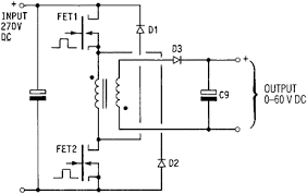 Ignore the secondary and D3 and C9, the choke under test is just the bare primary. Being lazy, I just pinched the above circuit from the internet. Both mosfets turn on simultaneously with a 50% duty cycle waveform, and current through the inductor ramps up to some high peak current, drawing power from the very large electrolytic across the dc supply. When both mosfets turn off, all the stored inductive flyback energy is returned to the electrolytic minus any conduction losses, via D1 and D2. The clever thing about this, is that the current can ramp up to perhaps thirty or eighty amps, and almost all of that is fully recovered during flyback. The dc source only has to supply the losses, perhaps one or two amps. The whole thing can be powered by the typical 0-30v 0-3amp lab power supply, and test chokes up to crazy high peak currents, limited only by mosfet and diode ratings, and safe ripple current in the electrolytic. If the inductor current is monitored with a suitable Hall current sensor, the current ramp up can be observed on an oscilloscope. By adjusting both the drive frequency, and dc voltage, starting at low voltage and short on time, its possible to gradually increase the current ramp amplitude up to a safe maximum that can be set usefully high. The duty cycle must be 50% (or less) so there is always sufficient off time for the current through the inductor to fall back to zero, so its best driven from a flip flop. Using this tester its possible to clearly see the onset of magnetic saturation of any particular core material and its air gap (if there is one). If for example you work out that the final choke needs fifteen turns to provide the required inductance, you can test with say sixty turns of much thinner wire. Saturation is determined by total ampere turns. If it saturates at 53 amps, for example, with sixty turns, you will know that it will go to 212 amps with only fifteen turns. As a test only takes a few seconds, we don't need to worry too much about thin test wire overheating, or even heatsinking on our mosfets and diodes. With only the typical bench power supply most of us will already have, and possibly a function generator, we can test some seriously large chokes with simple equipment. Highly recommended you try this. Its great fun and very instructive, and it can very likely all be quickly assembled from junk parts initially. Edited 2021-08-31 09:32 by Warpspeed Cheers, �Tony. |
||||
| poida Guru Joined: 02/02/2017 Location: AustraliaPosts: 1389 |
Ok, the way I make a choke is using $26 E core ferrite E 70/33/32 N27 pair of cores, RS part no. 47-9367 I grind a 1/2mm to 1mm gap in the center post. I use two pairs of these and wind a core with 3 x 6mm2 pvc insulated cable and about 6 turns. Put the 2 chokes in series. I end up with something costing $50 or so, 90uH and good for 90 Amps DC and still retain enough Henries. I use one of these chokes in my mppt design here https://www.thebackshed.com/forum/ViewTopic.php?TID=12027&P=17#147625 (pics and DSO traces showing non-saturating behavior) I used cheap pvc or urethane insulated cable. This is not a good idea. https://www.thebackshed.com/forum/ViewTopic.php?FID=4&TID=12773#155119 No shorted turns but it must have come close... I had a bad time working towards a suitable choke for my inverters. Some investigations and lovely photos of destroyed MOSFETs later it became clear to me that I needed to have not only enough inductance at all operating output power levels but importantly, adequate self resonant frequency. https://www.thebackshed.com/forum/ViewTopic.php?TID=9756&P=7#140055 I think for my builds, self resonant frequency of 17Hz was too low and kept blowing inverters (both Aliexpress boards and Madness's very robust boards) Once I got to 35Hz or more, they last for ever. Crazy, really. I used a 10uF cap across the secondary and it gave 17Hz. Something like 2.4uF was settled upon and 35Hz. Your inverter will need something different and only you can work out what it will be. Warp likes 75Hz and for my builds that means a cap of about 1uF or less. You just need to find the resonant freq by experimentation. Sometimes you build an inverter that is nearly indestructible. This one uses a 1,500VA toroid, 4 x 4 HY4008 MOSFETs and the double E core choke described above. I designed it to be "2kW" capable and built it as a spare to test to destruction in the name of science. After testing and no destruction I feel it's part of the family now and deserves to live a long life. Peak power was measured at 11 kW during the compressor motor startup. https://www.thebackshed.com/forum/ViewTopic.php?TID=9409&P=47#166980 That power level is insane. wronger than a phone book full of wrong phone numbers |
||||
| Warpspeed Guru Joined: 09/08/2007 Location: AustraliaPosts: 4406 |
Agree, for higher voltage MPPT solar controllers, gapped ferrite is the material of choice. Two reasons, there will be a much higher ac switching voltage across the winding, so core loss will be a significant factor. And a solar controller never sees massive peak overloads as solar panels are themselves current limiting. The choke in a low voltage battery powered inverter is rather different. It will see a much lower ac voltage across the winding, and so core heating and core losses are far less of a problem. We can get away with much more lossy and cheaper cores to our advantage. But an inverter may have to survive huge short term surge overloads, and choke saturation becomes the major problem. Powdered iron and steel cores really start to look attractive because of the very high saturation flux levels and lower cost in larger sizes. There is also some middle ground where there is a choice. For us, using what you already have is often an excellent reason. Cheers, �Tony. |
||||
| Warpspeed Guru Joined: 09/08/2007 Location: AustraliaPosts: 4406 |
I will go into this transformer resonance topic a bit later. For now, we need to get Mr Teapot fixed up with a really nice choke. Cheers, �Tony. |
||||
| teapot Newbie Joined: 22/08/2021 Location: United KingdomPosts: 22 |
Indeed, I am working on that and will update you when I have made some progress! |
||||
| BenandAmber Guru Joined: 16/02/2019 Location: United StatesPosts: 961 |
First off I'll say I am just a small little peon that knows very little among giants so tall I have to climb the extension ladder just to see the expression on their face! Ever single person who has gave you advice are giants and get payed big bucks for what they give freely I think in this day and age that is incredible! The power jack inverters I have worked on seem to have one bank of fets that gets hotter than the rest This is in the programming I had a friend reprogram a power jack control board with a program used on a different inverter this fixed the one bank being hotter It has a perfect sine wave and is so much better than it was with pj programming It has around a half amp of idle current I tried countless chokes and none is better than two turns around 2 pj choke cores People on here may find it hard to believe but there is completely silent trannys I built all over the US Many happy greatly happy people some of which might be a surprise If you look at my post on here you will see my little I know I had lots of help and I am forever grateful Warpspeed finally made me understand how to wind a tranny The first few I tried to do math but was gave the answers I now guess the high side turns and wind one of the parallel windings Then I use the light bulb switch plug it in to outlet and check the idle current Then I add 8 or 10 more turns and check idle current I keep doing this until the idle dosen't go down much for the extra turns This is how warpspeed told me to do it if you do it this way you will have the lowest idle current possible for the core you are using Not only that it will be silent and perform better than any other Keep in mind you also need to wind it tight be very close to warps mm squared amperage rating I don't know the math for mm squared but know on the us awg chart if you go down one rating like instead of 20 amps for 12 gauge steep down to 15 gauge rating of 15 amps but use that rating at the short time absolutely Max amp rating If you do your tranny just like I said you will be more than happy Keep in mind like a great said already the idle amps when plugged in to a outlet will be lower than in the inverter The smaller trannys idle I have wound 2k or so are around 20 watts 6k or so under 30 watts usually and 10k and above still in the 30 some watt range I go poidas a hell of a good guy way on chokes I've never used anything except for ferrite materials for chokes if it's not broken I don't fix it I have used TV yokes square round of all kinds of ferrite materials It has to hold enough turns of the size wire you need to get around 60mh If it gets hot when testing it is to small bigger is always better in my book But keep in mind I keep many big chokes around and use the one the tests out best If you use a scope on ac out put a ac clamp meter and a dc clamp on the battery input you will find its very helpful to make the ac voltage on dc battery input as low as possible and your ac output on scope will show this also I don't stick real close to the 60mh I will add a few more turns and test again I keep on trying different things until it works Then I try a bunch of out put capacitors until I have perfect sin wave and lowest possible idle current The cap part is frustrating for me it's totally trial and error I am sorry this is so long hope it helps You can take to the bank what these guys tell you Praying for lots of you guys sounds bad from rumors I hope not true Have a blessed day every one be warned i am good parrot but Dumber than a box of rocks |
||||
| Warpspeed Guru Joined: 09/08/2007 Location: AustraliaPosts: 4406 |
Great stuff  Cheers, �Tony. |
||||
| teapot Newbie Joined: 22/08/2021 Location: United KingdomPosts: 22 |
Please don't get me wrong, I am eternally grateful for the help and advice that you and all the other contributors to this forum have given me. I know that nobody is being paid for that advice and I certainly don't take anyone for granted. I'm sorry if I came across that way - please forgive me. I would gladly pay for the advice I have received and it is far greater than I ever expected. Indeed in future one I have gained some more experience I hope to be able to offer such advice to other novices like I am at the moment. To everyone on this forum - A BIG THANK YOU. kindest regards, Paul. |
||||
