
|
|
Forum Index : Microcontroller and PC projects : PCB for VGAmite?
| Author | Message | ||||
Grogster Admin Group Joined: 31/12/2012 Location: New ZealandPosts: 9066 |
Wow - lots of replies! I do tend to think too much around the VGA colour outputs is OTT as others have mentioned. So far, I like Jim's post above the best, cos you can select a colour you want, and get the loading right to keep the monitor happy AND it is as simple as three resistors. We'd just need a small chart to indicate what values to use for what. That could be on the silkscreen I am sure. While I read everyone's posts, I do see that bloody design-by-committee problem already raising it's head - there is no way to please everyone, so the three resistors/silkscreen chart is how I will do things at this point. Was never going to entertain the PWM control idea, but others could. And to members asking: YES - all the gerbers will be completely open and available for download here. Anyone can take them and customize to whatever they personally want. I think that is the best way forward, rather then trying to design in everything everyone wants - I have been down that path before, and it is damn near impossible to do it.  I use Sprint Layout 6, for those asking what software I use. Exported gerbers are standard RS274X and Excellon drill data in a ZIP file - pretty standard stuff. I will also include the LAY6 file for anyone else using Sprint Layout. On the case, much as I like the Altronics one, I have to agree with matherp, and if we can only get it from Altronics, that kinda screws that idea. What about just using the CMM1/CMM2 case? It is available globally and would give us enough room to get everything in I think, including a CR2032 battery for the RTC. Members might think that is too big, but I still consider it a cute little case.  As a slight digression, I too was surprised by CR1220 button cells being hard to find in some countries. I thought you could get most button cell sizes anywhere. Are there any issues getting hold of CR2032 cells anywhere? Smoke makes things work. When the smoke gets out, it stops! |
||||
| phil99 Guru Joined: 11/02/2018 Location: AustraliaPosts: 1799 |
@TassyJim Yes, came to the same conclusion. If the board has just has 3 x 2 pin header sockets people can play with resistor values to get whatever they want. For anything more ambitious a daughter board can be plugged into the sockets. Edit Cross posted with Grogster. Looks like it is settled. Edited 2021-12-01 09:29 by phil99 |
||||
| Turbo46 Guru Joined: 24/12/2017 Location: AustraliaPosts: 1593 |
Sounds good Grogster, remembering matherp's original post: The PS2 connector and pullup resistors could be omitted if the microbridge (or similar) and USB socket are fitted. I like the header suggestion for Jim's VGA resistors by Phil. If using the CMM1/2 case you could also make the front and rear panels as PCBs. Either battery is widely available here, the CR2032 more so. Bill Keep safe. Live long and prosper. |
||||
| flasherror Senior Member Joined: 07/01/2019 Location: United StatesPosts: 159 |
I was hoping you were using Eagle, otherwise design can't be easily modified except perhaps by Sprint (since it can modify gerbers but it seems to be unique in that capability) Dumb question here, but what is the CMM1/2 case? Datasheet link? CR2032 are common worldwide and are probably the best choice assuming there is PCB space. I've had trouble finding CR1220s in stores but I have noticed that many car key fobs use CR1632 so that might be another option. |
||||
| Turbo46 Guru Joined: 24/12/2017 Location: AustraliaPosts: 1593 |
From the CMM1 parts list: 1 Plastic Box 140x110x35 mm (Multicomp G378A, Jaycar HB-5970, Altronics H0472, Element14 1526699) Bill Keep safe. Live long and prosper. |
||||
| Mixtel90 Guru Joined: 05/10/2019 Location: United KingdomPosts: 5742 |
*Availability* of the CMM2 case wasn't a problem here, neither was *availability* of the CR1220 (?). The problem was in getting them in 1-off quantities at a reasonable cost. Component distributors like Farnell have them, but on top of the catalogue price we have postage (6.00-10.00 UKP - only free on orders over 40.00 UKP) then VAT applied to all items (including the postage) at 20%. It's rarely cost-effective as they don't sell *all* the components for a project. I ended up getting both items from ebay sellers (and there was only one that was much cheaper than Farnell unless I was willing to wait for one from China). A particular problem (for me) was that lovely little C interpreter PCB. It uses a stacked connector that only seems to be available from Mouser (IIRC). It costs a fortune to buy just one unless you need enough stuff to make up a big order. We just don't have electronics shops now... :( Edited 2021-12-01 18:12 by Mixtel90 Mick Zilog Inside! nascom.info for Nascom & Gemini Preliminary MMBasic docs & my PCB designs |
||||
| matherp Guru Joined: 11/12/2012 Location: United KingdomPosts: 8592 |
Quick hack 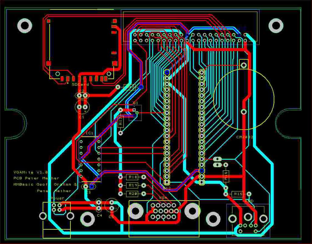 VGAMite - Project.pdf VGAMite V1.0.zip VGAMite.zip Edited 2021-12-01 22:02 by matherp |
||||
| Grogster Admin Group Joined: 31/12/2012 Location: New ZealandPosts: 9066 |
Seeing as you have already essentially done a design to fit that box matherp, and I have not even started yet, do you just want to take over at this point? Seems silly for me to re-invent the wheel. Between your coding and porting, and PCB's on the side, do you EVER sleep? Smoke makes things work. When the smoke gets out, it stops! |
||||
| flasherror Senior Member Joined: 07/01/2019 Location: United StatesPosts: 159 |
I suspect "matherp" is either: 1. an advanced alien life form 2. a highly sophisticated artificial intelligence 3. an advanced alien life form equipped with a highly sophisticated artificial intelligence Currently I'm leaning towards #3 |
||||
| phil99 Guru Joined: 11/02/2018 Location: AustraliaPosts: 1799 |
Nice layout. The spacing between R18, 19, 20 appears to be 0.15". Could this be changed to 0.1" or 0.2" to fit optional header sockets? Q1 (if fitted) Vbe will affect the values of the resistors a little. (3.3 - 0.6 - 0.6) / (0.6 / 75) = 262.5 ohms |
||||
| matherp Guru Joined: 11/12/2012 Location: United KingdomPosts: 8592 |
It was trivial to do because I had all the layout and components from the CMM2, only took about 90mins in total. Yes: I've got 5 in production at JLC, once they arrive and are proven good (or otherwise) I can make any tweaks needed and release the final versions. Note the MCP221A/Microbridge can be left off and any USB/UART used on the edge connector pins (ROB) |
||||
| Volhout Guru Joined: 05/03/2018 Location: NetherlandsPosts: 3558 |
Hi Peter, Some things you may want to address. 1/ The Vbat is hardwired to one of the 40 pins on the IO connector. Although completely in line with "routing out all pins to the IO header" this one may cause unintended problems, because the Vbat is 3V, even when the VGAMite is off. So safe plugging/unplugging and accidental shorts while wiring a breadboard is possible. 2/ To improve VGA quality it may be better to keep Q1 as much as possible in linear mode. That can be achieved by connecting it's collector to +5V (not +3.3V). 3/ Order of assembly is important. Put the SD card header on first, the 0.1" pitch last. You where fast, too fast for others here.... B.t.w. good choice to put the VGA, PS2 and USB (fixed witing) on one side, and the 40pin and SD card the other side (user access, experimenters area). Volhout Edited 2021-12-02 17:59 by Volhout PicomiteVGA PETSCII ROBOTS |
||||
| matherp Guru Joined: 11/12/2012 Location: United KingdomPosts: 8592 |
I'll put a diode in the line to the edge connector. That way you can use an external battery but it won't backfeed. Now you are talking that strange analogue language. Phil99: do you agree with the proposal? Yes: but the VGAMite doesn't use card detect or write protect so unlike the CMM2 it doesn't matter if you short those tiny pins to the case Thanks, that was my thinking Edited 2021-12-02 18:53 by matherp |
||||
| Turbo46 Guru Joined: 24/12/2017 Location: AustraliaPosts: 1593 |
A transistor takes a small time to come in and out of saturation - like the propagation delay of a logic gate. If it works for Phil, then whatever it is cannot be significant enough to affect the display. Connecting the collector to +5v would avoid the transistor going into saturation and reduce any delay but increase the power dissipation of the transistor. Bill Keep safe. Live long and prosper. |
||||
| phil99 Guru Joined: 11/02/2018 Location: AustraliaPosts: 1799 |
Re Q1 Volhout and Turbo64 are correct and for a 1080 screen might make a visible difference but at 640 x 480 less so. On the ASCII terminal I used 3.3V and it is respectably sharp but using 5V instead costs nothing, unless it makes the layout difficult. I think the output capability of this chip is sufficient to drive all three VGA pins without Q1 so those wanting the sharpest image can omit it, linking the B & E pads and using 330 ohms or more for R18 to 20, as suggested by TassyJim Could some prototyping pads go in the empty spaces? |
||||
| robert.rozee Guru Joined: 31/12/2012 Location: New ZealandPosts: 2290 |
hi peter, i'd suggest placing a row of 0.1" spaced pads to the left or behind the SD socket, duplicating all the connections to the SD footprint. this way, if someone does make a hash of soldering the socket, or the socket fails and can't be easily removed without damage, the user has the option of wiring up an SD socket on a breakout board. also, the pads for Q1: the corner of the square pad is uncomfortably close to the base pad. consider making all three pads round, and spacing them out more to make soldering easier. no reason you can't have 0.2" between pads - transistors have plenty long enough leads to reach  and you have a near-circular 5v(?) track around the perimeter of the board. consider removing the segment that runs clockwise from just to the left of the VGA connector, under the power/USB socket, and between the SD socket and 40-pin connector. the location it runs to (on the 40-pin connector) can instead pick up 5v from the top-right pin on the 40-pin connector that is connected to 5v from the other direction. cheers, rob :-) |
||||
| Turbo46 Guru Joined: 24/12/2017 Location: AustraliaPosts: 1593 |
One final comment on the VGA output if I may: In Silicon Chip magazine April 2013 circuit notebook section a reader described a colour output for the original Mono Maximite. It took the white output from the Maximite and used a rotary switch and one SPST switch to select one of six colours plus white. Blue, Green, Cyan, Red, Purple, Yellow and White. I don't know if it's OK to show a copy of the circuit, so I wont. The colours were selected by connecting the white output from the Maximite selectively to the three Red, Green and Blue inputs of the monitor. Blue: Blue Green: Green Cyan: Green + Blue Red: Red Purple: Red + Blue Yellow: Red + Green White: Red + Green + Blue I'm not sure how useful some of those colours are but this could easily be achieved with the circuit I proposed above, it is a simple and proven circuit from the original Maximite. 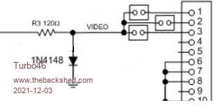 No Amber I'm afraid but that could be achieved with a suitable resistor replacing the link for the Green colour. I'm not in a position to try that right now but if someone with a Blackpill can I'd appreciate their comments Bill Keep safe. Live long and prosper. |
||||
vegipete Guru Joined: 29/01/2013 Location: CanadaPosts: 1083 |
For colour selection, a quad AND (ex: 74xx08) or NAND (ex: 74xx00) could be useful. VGA out goes to one side of each gate, other side goes high or low to set colour. Fourth gate could be used for intensity. Things get interesting when the selection lines instead are connected to I/O pins. Then a running program can control its own colour output. If the running program can sync to the VGA interrupts, colour control becomes possible, to some degree, on a line by line basis. Visit Vegipete's *Mite Library for cool programs. |
||||
| Mixtel90 Guru Joined: 05/10/2019 Location: United KingdomPosts: 5742 |
@Turbo46 Each colour input of the monitor has a 75R resistor to ground. That means that to drive the monitor to full white you need to think of the inputs as being a single 25R resistor. At 0.7V (full drive) you need 28mA into 25R. The Micromite could just about manage that, but the BP can probably only manage about 12mA max on a single pin. That's why the emitter follower circuit is a good way to go - the output pin only supplies a very low current. This is my attempt to explain why a single pin direct drive is "a bad thing". :) Because of the 120R resistor in your circuit you will only reach about 0.57v into 25R even if the pin can supply 23mA, so you won't get anywhere near full white (probably around half brightness at best). With 2 colour channels driven (e.g. green+blue to get cyan) the output is almost bang on 0.7v into 37.5R if the pin can supply 20mA, it might be a lot dimmer than this. With a single channel driven the output would be 1.27v into 75R with 17mA from the pin. The diode will clip it, but the output current from the pin will probably sag the voltage anyway. Basically, direct drive from a single pin only works anywhere near properly with a single colour channel driven. (I hope I've done my sums right - please forgive me if I've screwed up too much!) Mick Zilog Inside! nascom.info for Nascom & Gemini Preliminary MMBasic docs & my PCB designs |
||||
| Turbo46 Guru Joined: 24/12/2017 Location: AustraliaPosts: 1593 |
Mono Maximite Not my circuit. I have done the maths. You You can tell Geoff the Mono Maximite won't work although mine does. Go figure. Bill Keep safe. Live long and prosper. |
||||
