
|
|
Forum Index : Microcontroller and PC projects : PCB for VGAmite?
| Author | Message | ||||
| Turbo46 Guru Joined: 24/12/2017 Location: AustraliaPosts: 1638 |
@Grogster, This would be my first pass at a circuit for VGA. Untested and I don't have an easy way to test it. 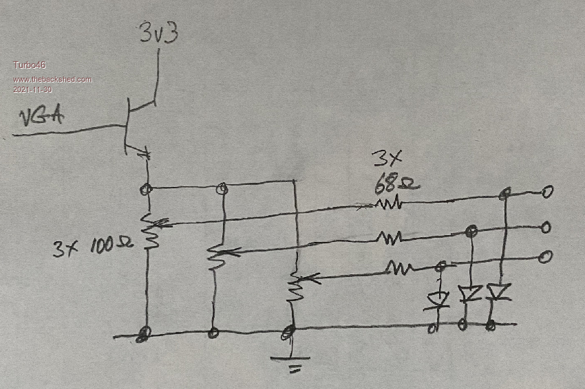 But I really think it's all a bit OTT and unnecessary. I think Volhout's suggestion is all that's needed, perhaps allow for different value resistors in place of the links to adjust the colour if it's needed. The Altronics case says it's made by RITEC but I couldn't find it on their site either. Bill Keep safe. Live long and prosper. |
||||
| Mixtel90 Guru Joined: 05/10/2019 Location: United KingdomPosts: 7823 |
I started playing with the case that Peter suggested originally - just to see if it's possible to fit everything in. On the CAD, I'm managing to fit VGA + PS/2 connectors at one end and a 13+13 90 degree IDE socket at the other with about 7mm to spare. Sizes are approximate as the drawings in the advert don't appear to be to scale and supply insufficient information. The BP is running at right-angles to the case so, at the moment, there is no access to either the USB socket or debug connector. This is all very early stages and I've not considered any sort of VGA colour change. I've not even got the battery on the board (or a power supply connector, but that could be the USB socket). I put +5 +3V3 and GND on the IDE socket anyway. I've still not sorted out the SDcard socket either, but I'm going to attempt a full-size one on the side of the case (although the cutout might be a pig). If it is I'll try putting it at the end and move the VGA socket to the side to make the cutouts easier. Based on the above, I doubt very much if it's possible to use a RPi case unless it's one of the oversize ones intended to take additional expansion. VGAmite-box-001.pdf In theory I don't think the diodes are necessary, although they may help with colour purity. The supply on the board can be assumed to be a constant 3v3 so just calculating the resistors to give an output not exceeding 0.7v into 75 ohms should be sufficient. . Edited 2021-11-30 18:35 by Mixtel90 Mick Zilog Inside! nascom.info for Nascom & Gemini Preliminary MMBasic docs & my PCB designs |
||||
| robert.rozee Guru Joined: 31/12/2012 Location: New ZealandPosts: 2428 |
be wary: 2.7v into 33 ohm (3x 100 ohm in parallel) equals 80mA of current consumption JUST for the one-transistor video driver! cheers, rob :-) |
||||
| robert.rozee Guru Joined: 31/12/2012 Location: New ZealandPosts: 2428 |
consider these for the SC card: https://www.ebay.com/itm/123904123484 and: https://www.ebay.com/itm/152201929853 no obvious sign of resistors. cheers, rob :-) Edited 2021-11-30 19:14 by robert.rozee |
||||
| Turbo46 Guru Joined: 24/12/2017 Location: AustraliaPosts: 1638 |
80mA and more through the monitor inputs. The PN100 is good for 500mA and 625mW so that should be OK. Minimum gain is 80 so only about 1mA base current needed. I did look at that because I was concerned about the load and dissipation. Bill Edit: I still think it's OTT. Edit2: 80mA+ has implications for the power supply though. Edited 2021-11-30 19:29 by Turbo46 Keep safe. Live long and prosper. |
||||
| thwill Guru Joined: 16/09/2019 Location: United KingdomPosts: 4301 |
Hi folks, Shame if it won't fit in a Raspberry Pi case given there ubiquity and low price point, but I guess it can't be helped. Disagree with the disagreement  . If it ends up in an "oversized" case I would suggest putting in the anchor points and pin holes for a second PS/2 (mouse) and an ESP, and however more holes you can fit in ala CGs versions of the CMM2. That way the end-users get to decide what the port is for and have the choice to wire up whatever else they can fit inside the box. I am not asking for mouse of ESP support to be added to the firmware! . If it ends up in an "oversized" case I would suggest putting in the anchor points and pin holes for a second PS/2 (mouse) and an ESP, and however more holes you can fit in ala CGs versions of the CMM2. That way the end-users get to decide what the port is for and have the choice to wire up whatever else they can fit inside the box. I am not asking for mouse of ESP support to be added to the firmware!Best wishes, Tom MMBasic for Linux, Game*Mite, CMM2 Welcome Tape, Creaky old text adventures |
||||
| phil99 Guru Joined: 11/02/2018 Location: AustraliaPosts: 2583 |
Re the VGA out. The diodes can be omitted as all the monitors I have tried don't mind a bit of overdrive. Up to 1.5 V seems ok. A 270 ohm series resistor will ensure it stays under 0.8V for 3.3V supply. With (270 + 75 ohms) x 3 at 3.3V = 29mA so the emitter follower may not be needed for this. The MX270 in the ASCII terminal did need it. To make it easy to customize colours provide 2 x 3 pin female headers to plug the resistors into. (or 3 x 2 pin if the resistors stand vertical) If there is room could there be a small set of prototyping pads near the VGA connector for custom colour control methods? Eg. PWM control of the colours would use 3 transistors and a few resistors etc. Phil |
||||
| flasherror Senior Member Joined: 07/01/2019 Location: United StatesPosts: 159 |
For the VGA colors, jumpers to select green/white/amber is enough, anything beyond that is overkill. Better to use PCB space to add an on-board beeper and/or audio out via 1/8" line out jack? For the case being considered, anyone have a USA vendor link/datasheet? I like the idea of USB keyboard support rather than PS2 (PS2 keyboards aren't easy to find in stores), but might need additional chip required to implement? What's a cheap micro with USB *host* support to implement an USB to PS2 converter? (That way Peter doesn't have any extra work to do). Maybe there is a way to bit bang USB and use an even cheaper device? Crazy idea: it could also support a USB mouse and translate mouse movements into cursor keys and (enter/space) key presses ? Might be good for playing Centipede or Missile Command as well as GUIs. I feel some sort of wireless connectivity is a must have (ESP8266 or one of the other modules I mentioned earlier). Otherwise, how many VT100 terminals are we gonna create? @Grogster Can the PCB design files be open source so it can be used as a starting point for custom boards? What PCB software are you using? |
||||
| Turbo46 Guru Joined: 24/12/2017 Location: AustraliaPosts: 1638 |
 Does the saying "A camel is a horse designed by a committee" ring a bell? K I S S Bill PS While I think my circuit above would work, the pots would only be effective for about half the adjustment because anything above half way would be clipped by the diodes. Keep safe. Live long and prosper. |
||||
| Mixtel90 Guru Joined: 05/10/2019 Location: United KingdomPosts: 7823 |
On that layout I'm playing with you'll be lucky to get a Microbridge chip in the box! I'm rearranging it all to get a CR2032 in. I agree with Peter, the little one isn't easy to source. I had to buy 2 off ebay as no-one round here had even heard of them. No, it won't be all singing all dancing. There isn't room and I don't want to go for a bigger case 'cos I'm pig-headed and this is a "design challenge", as my old boss used to say. :) Mick Zilog Inside! nascom.info for Nascom & Gemini Preliminary MMBasic docs & my PCB designs |
||||
| CaptainBoing Guru Joined: 07/09/2016 Location: United KingdomPosts: 2170 |
wow! you have electronics component shops near you??? jealous I remember the glory days of the 80s, every parade of shops had a surplus electronics shop... Loutronics, Linways, Stan Reed and the mother-lode of Edgware Road and Tottenham Court Road... and it died back and we were left with just Maplins... and then there was none.  Edited 2021-11-30 23:54 by CaptainBoing |
||||
| Volhout Guru Joined: 05/03/2018 Location: NetherlandsPosts: 5030 |
If you design a VGA terminal with build in basic, the target would be that it is a terminal. A nice way to mount a terminal is at the back of the monitor, using the VESA mounting points. These are not really close together, so you have a bigger mother board, and the housing could be a bit bigger too. Like the CMM2 housing... That would also allow for a nice larger CR2032, and an ESP footprint, a full size SD card and potentially a USB/PS2 bridge chip, and of coarse a microbridge. PicomiteVGA PETSCII ROBOTS |
||||
| Turbo46 Guru Joined: 24/12/2017 Location: AustraliaPosts: 1638 |
My preferred version of the VGA output. 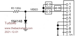 A modified copy of the mono maximite circuit. The links allow selection of one or more colours and for those who want to fiddle, vertically mounted resistors could replace the links to produce any colour they want. If a larger CMM1/2 box was used the board could include a 'sea of holes' to cater for those who want to add all manner of weird and wonderful things. Maybe use the same rear connector as the CMM2 so that PI cobblers can be used to connect to the external world. Bill Keep safe. Live long and prosper. |
||||
| thwill Guru Joined: 16/09/2019 Location: United KingdomPosts: 4301 |
Emphasis mine See @bigmik, I didn't invent the term cobblers for these adapters, even one of your fellow countrymen is using it. Is there an issue that some cobblers tie the ground lines together and if they are not also grounds on the 'mite then you are in trouble - or have I invented that. Best wishes, Tom Edited 2021-12-01 02:12 by thwill MMBasic for Linux, Game*Mite, CMM2 Welcome Tape, Creaky old text adventures |
||||
| flasherror Senior Member Joined: 07/01/2019 Location: United StatesPosts: 159 |
While everybody's tossing around ideas, what about the PCB size? Does it make sense to try to achieve a cheap 100x100mm PCB (assuming that's possible) which leaves extra space inside case or Design larger PCB (to fit whatever case is selected) with 0.1" prototyping area, optional "user installed" connectors etc? Edited 2021-12-01 02:31 by flasherror |
||||
| Mixtel90 Guru Joined: 05/10/2019 Location: United KingdomPosts: 7823 |
Well, it's like stuffing a cuddly toy... :) VGAmite-box-002.pdf I'm not saying this is definitive, of course (note that the SD card isn't connected!). I'm just stuffing bits in a box. For reference, the polylines I've used for tracks are supposed to be 0.6mm wide. This isn't a PCB layout program. If someone would like to use a bigger board then by all means do so - I'm only playing. :) If a case is to be used then there probably aren't a lot of options. I had a job getting hold of the case for the CMM2 as it worked out very expensive from many suppliers by the time postage, handling & vat had gone on. Cheap enough if you want 20 or you want over 30 UKP in parts (+vat), but not for a single one. Edited 2021-12-01 03:07 by Mixtel90 Mick Zilog Inside! nascom.info for Nascom & Gemini Preliminary MMBasic docs & my PCB designs |
||||
| flasherror Senior Member Joined: 07/01/2019 Location: United StatesPosts: 159 |
The reason I mentioned 100x100mm is that the cost for this size is same as slightly smaller prototype PCBs (JLCPCB), so case aside, there might not be any good reason to make an extraordinary small PCB (and compromise functionality to achieve the small size). Not sure if anyone else agrees. I'm surprised there isn't a case that is designed to fit a 100x100 PCB but I am not an enclosure expert so maybe there's one that I don't know about. |
||||
| Mixtel90 Guru Joined: 05/10/2019 Location: United KingdomPosts: 7823 |
It's not just a case of finding a box the right size, it's not good if there is only a single manufacturer or if it's only available at reasonable cost in one country. eg. a box in the US might be the equivalent of 4 UKP in the UK, but US postage costs might easily add another 10 UKP to that. Mick Zilog Inside! nascom.info for Nascom & Gemini Preliminary MMBasic docs & my PCB designs |
||||
TassyJim Guru Joined: 07/08/2011 Location: AustraliaPosts: 6266 |
For the video out, I refer you to my earlier post: https://www.thebackshed.com/forum/ViewTopic.php?TID=14328&P=2#178157 3 resistors. One each to red green blue. Provided the user doesn't use values below 270 ohms (I would prefer 330 if the display is bright enough), the pic will not be over-loaded and the monitor will not be over-driven. Minimum load on the power supply. Blue omitted, 680 ohms to green and 330 ohms to red for amber. If you want to get really fancy, a 470 ohm pot in series with a 270/330 ohm resistor but I call that overkill. Jim VK7JH MMedit |
||||
| Mixtel90 Guru Joined: 05/10/2019 Location: United KingdomPosts: 7823 |
Final attempt, I think. * Fit 1, 2 or 3 resistors to mix VGA colour. * 1-of-4 link to set SD card enable pin * isolation link to disconnect BOOT1 pin during setup * on-board LED wired out (keep the current low as original is still in circuit) * power supply is via USB connector * RESET pin is on GPIO port * Console connections are on GPIO port I'd like to have grided the 5v but I've not got an easy route now. VGAmite-box-003.pdf . Mick Zilog Inside! nascom.info for Nascom & Gemini Preliminary MMBasic docs & my PCB designs |
||||
| The Back Shed's forum code is written, and hosted, in Australia. | © JAQ Software 2025 |
