
|
|
Forum Index : Microcontroller and PC projects : PicoMite VGA Edition beta releases
| Author | Message | ||||
| Mixtel90 Guru Joined: 05/10/2019 Location: United KingdomPosts: 7865 |
Use any little old npn transistor and a schottky diode. :) Mick Zilog Inside! nascom.info for Nascom & Gemini Preliminary MMBasic docs & my PCB designs |
||||
| Volhout Guru Joined: 05/03/2018 Location: NetherlandsPosts: 5058 |
Not sure what you plan to do with this Tinine, but the circuit proposed by Peter, is a logic level shifter that is used in open drain busses (like I2C, and maybe PS2). It works by the grace of the BSS138 specifiction for Vgs (the threshold). This logic FET has a Vgs of around 1.5V, and this coincides with the logic threshold in TTL and 3.3V CMOS busses. For video level level shifting this is not very usefull. Volhout By the way, something people often forget if you want to do logic level shifting on open drain (open collector) busses is that you can simply make a voltage divider. The pullup resistor to 5V (i.e. 3.3k) can be combined with a pull-down resistor (i.e. 6.8k) to convert the 5V to 3.3V. Works the same as the FET circuit above. Edited 2021-12-15 23:42 by Volhout PicomiteVGA PETSCII ROBOTS |
||||
| matherp Guru Joined: 11/12/2012 Location: United KingdomPosts: 10240 |
Absolutely correct. For reference the colours available in order will be #define WHITE RGB(255, 255, 255) //0b1111 #define YELLOW RGB(255, 255, 0) //0b1110 #define LILAC RGB(255, 128, 255) //0b1101 #define BROWN RGB(255, 128, 0) //0b1100 #define FUCHSIA RGB(255, 64, 255) //0b1011 #define RUST RGB(255, 64, 0) //0b1010 #define MAGENTA RGB(255, 0, 255) //0b1001 #define RED RGB(255, 0, 0) //0b1000 #define CYAN RGB(0, 255, 255) //0b0111 #define GREEN RGB(0, 255, 0) //0b0110 #define CERULEAN RGB(0, 128, 255) //0b0101 #define MIDGREEN RGB(0, 128, 0) //0b0100 #define COBALT RGB(0, 64, 255) //0b0011 #define MYRTLE RGB(0, 64, 0) //0b0010 #define BLUE RGB(0, 0, 255) //0b0001 #define BLACK RGB(0, 0, 0) //0b0000 |
||||
| Mixtel90 Guru Joined: 05/10/2019 Location: United KingdomPosts: 7865 |
That's a bi-directional level shifter. Both sides are normally pulled high. Pull the High side down and the diode pulls the low side down to around 0.4v. Pull the low side down and the mosfet turns on, pulling the high side down. I'm sure I've seen this done using a schottky diode where the mosfet s-d diode is and an NPN transistor with it's emitter where the mosfet source would be. There may or may not have been a series resistor in the base. I think Tinine's comment was on the availability of that mosfet! Mick Zilog Inside! nascom.info for Nascom & Gemini Preliminary MMBasic docs & my PCB designs |
||||
| CaptainBoing Guru Joined: 07/09/2016 Location: United KingdomPosts: 2170 |
pretty much any "logic level" FET will do, in this application there is nothing idiosyncratic about the chosen device that makes it vital here. I use a very similar (read identical) circuit on my universal IO board and SI2302 (20V) FETs do a fine job. These are readily available. Edited 2021-12-16 01:54 by CaptainBoing |
||||
| Volhout Guru Joined: 05/03/2018 Location: NetherlandsPosts: 5058 |
As said before, remove the fets, 2 resistors will do the job. PicomiteVGA PETSCII ROBOTS |
||||
| Mixtel90 Guru Joined: 05/10/2019 Location: United KingdomPosts: 7865 |
The main problem with the 2 resistor method is that it's quite high impedance. If the input stage is a mosfet the resistance and gate capacitance restrict how fast you can shove the data through. You can reduce the resistor values to reduce the problem a bit but that's at the expense of output loading. Otherwise, it's a good method. I still reckon that for interfacing a PS/2 keyboard just two cheap zeners will do it, and they take up half the board space of four resistors or a mosfet and two resistors. Mick Zilog Inside! nascom.info for Nascom & Gemini Preliminary MMBasic docs & my PCB designs |
||||
| Tinine Guru Joined: 30/03/2016 Location: United KingdomPosts: 1646 |
It was an attempt at humour  I realise that there are always alternatives. Looking at the general shortage of semiconductors, it seems to be SMDs that are affected mostly. This helped me to decide to stick with socketed devices for my current project.  |
||||
| phil99 Guru Joined: 11/02/2018 Location: AustraliaPosts: 2611 |
Back to the keyboard. Had a think. The need for level shifting assumes that keyboards that drive to 5V exist. As PS/2 is two way, can they exist without damaging the host, even with the mosfet shifter? If the KB drives high while the host pulls low something will break. A 1k0 series resistor with 3V3 zenner(*) at the host end is the best way to protect against this imaginary KB. A resistive divider is unlikely to work as the pullup resistor is a "third wheel" messing up the voltages for keyboards that don't drive high (all of them). (*) A blue or white LED should work too. A 2V7 zenner might not work as low voltage ones start to conduct early and don't reach their specified voltage until passing 10mA. Thunk. (End Think) Edited 2021-12-16 09:52 by phil99 |
||||
| Mixtel90 Guru Joined: 05/10/2019 Location: United KingdomPosts: 7865 |
An LED might be ok but check Vf first as some of them can be up near 4v. A 2v7 500mW zener (BZX55C27) should give 2v5 to 2v9 at 5mA. We want about 2v1. If you can find a 3v0 zener than that should go up to 3v2, but a 3v3 zener could go as high as 3v5 which is marginal for safety. There are some pretty cheap voltage reference diodes at 3v0 which might be better than ordinary zeners at low currents but I've not checked them out. We can't predict the current through the zener precisely as that will depend on any pullups in the keyboard, but we can set a minimum of, say, 2mA by providing our own. Any keyboard that actually drives a line high rather than using a oc output with a pullup isn't PS/2 compliant and has probably already broken hundreds of PCs by now. :) I suspect that if any exist they are either home-built or some sort of modern Chinese implementation that was never tested on PCs. Mick Zilog Inside! nascom.info for Nascom & Gemini Preliminary MMBasic docs & my PCB designs |
||||
| flasherror Senior Member Joined: 07/01/2019 Location: United StatesPosts: 159 |
I haven't seen connections info for Picomite VGA with regards to the colors - what is the wiring? Also, is using colors optional (for example if you need more I/O and are content with mono Green/whatever color) to free up the additional color pins for I/O? Does this require different firmware or possibly OPTION VGA COLOR ON/OFF command? Edited 2021-12-17 00:40 by flasherror |
||||
| atmega8 Guru Joined: 19/11/2013 Location: GermanyPosts: 724 |
Just a few cents..: https://www.amazon.de/ARCELI-Converter-Bidirektionales-Shifter-Arduino/dp/B07RDHR315/ref=sr_1_8?__mk_de_DE=%C3%85M%C3%85%C5%BD%C3%95%C3%91&keywords=bs+175+level+shifter&qid=1639670385&sr=8-8 Level Shifter |
||||
| matherp Guru Joined: 11/12/2012 Location: United KingdomPosts: 10240 |
PicoMiteVGAV5.07.01b2.zip This version includes the option of 320x240 RGB121 colour display YOU MUST LOAD clear_flash BEFORE LOADING THIS VERSION Clear_flash.zip The pin for the mono VGA output has changed to GP20 Pins for colour VGA are: GP18 - BLUE GP19 - GREEN LSB GP20 - GREEN MSB GP21 - RED In both cases connect GP16 to VGA pin 13 (HSYNCH) GP17 to VGA pin 14 (VSYNCH) My wiring to get a good colour balance is as follows: pin GP18 220R to VGA pin1, 1n4148 from pin 1 to GND pin GP21 220R to VGA pin3, 1n4148 from pin 3 to GND 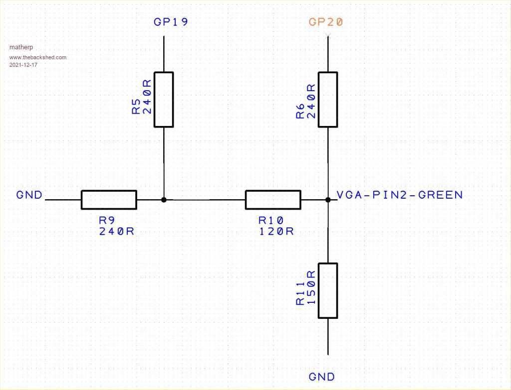 This version includes a fix to the XMODEM issue identified on another thread To enable colour VGA use OPTION COLOUR VGA ON To return to mono use OPTION COLOUR VGA OFF Use OPTION DEFAULT FONT fn [, scale] to select the font to be used for editing and the command line. The system defaults to font 1 (12x8) for the mono 640x480 display and font 7 (8x6) for the colour VGA display. This release also includes a significant change to the way the memory management works to allow for bigger programs. Previously the memory arrangement was 64K program space 32K Hash table for variables 64K Variable space for strings and arrays Now the default arrangement is 78K program space 78K variable space of which 32K is allocated to the hash table when the first variable is created. The hash table contains the name and data value for all simple variables and a pointer into the main variable space for arrays and strings This allows programs up to 78K to be edited, xmodemed and autosaved As before the variable space can always be extended at the expense of program space using OPTION MEMORY n where n is the number of 1K blocks to allocate to program space Although the colour VGA mode is intended to work in RGB121 mode you can use it in any way you wish depending on the way you wire the display. S, for example, if you want a grey scale display use a 4-bit R2R DAC on all the pins and use the pre-defined colours below or their RGB equivalents to select the grey level required (makes sense to set up some Basic constants to improve readability) #define WHITE RGB(255, 255, 255) //0b1111 #define YELLOW RGB(255, 255, 0) //0b1110 #define LILAC RGB(255, 128, 255) //0b1101 #define BROWN RGB(255, 128, 0) //0b1100 #define FUCHSIA RGB(255, 64, 255) //0b1011 #define RUST RGB(255, 64, 0) //0b1010 #define MAGENTA RGB(255, 0, 255) //0b1001 #define RED RGB(255, 0, 0) //0b1000 #define CYAN RGB(0, 255, 255) //0b0111 #define GREEN RGB(0, 255, 0) //0b0110 #define CERULEAN RGB(0, 128, 255) //0b0101 #define MIDGREEN RGB(0, 128, 0) //0b0100 #define COBALT RGB(0, 64, 255) //0b0011 #define MYRTLE RGB(0, 64, 0) //0b0010 #define BLUE RGB(0, 0, 255) //0b0001 #define BLACK RGB(0, 0, 0) //0b0000 Edited 2021-12-17 04:40 by matherp |
||||
| flasherror Senior Member Joined: 07/01/2019 Location: United StatesPosts: 159 |
How critical are the resistor values to maintaining proper color balance? Use 1% resistors or is it acceptable to use cheaper resistors with greater variance in value? What did you prototype with? I'm also wondering if just simply routing R/B/G(MSB) (with resistor/diode) to VGA connector will look that bad for a simpler PCB (although since in that case we're not using the Green LSB I'm guessing the range of green will not be correct?). Also, the Green LSB will still be assigned for VGA colour use and not be able to be used for I/O? Edited 2021-12-17 06:45 by flasherror |
||||
| phil99 Guru Joined: 11/02/2018 Location: AustraliaPosts: 2611 |
"How critical are the resistor values to maintaining proper color balance? Use 1% resistors or is it acceptable to use cheaper resistors with greater variance in value? What did you prototype with?" A) Human colour vision isn't too fussy and varies from person to person. B) Monitors vary greatly. Use a 220 ohm trim-pot for R10 and set it to what looks best to you on your monitor. |
||||
| matherp Guru Joined: 11/12/2012 Location: United KingdomPosts: 10240 |
NO: Use a 220 ohm trim-pot for R11 and set it to what looks best to you on your monitor. |
||||
| flasherror Senior Member Joined: 07/01/2019 Location: United StatesPosts: 159 |
Isn't VGA connector pin 1 RED instead of blue so that GP18 (Blue) should go to VGA Pin 3(the Blue pin)? Same for GP21 (Red) that should go to connector Pin 1(the Red pin)? Is this correct and is a typo in the quoted post? Edited 2021-12-17 09:32 by flasherror |
||||
| matherp Guru Joined: 11/12/2012 Location: United KingdomPosts: 10240 |
Oops - correction pin GP18 220R to VGA pin3, 1n4148 from pin 3 to GND pin GP21 220R to VGA pin1, 1n4148 from pin 1 to GND Edited 2021-12-17 18:20 by matherp |
||||
| matherp Guru Joined: 11/12/2012 Location: United KingdomPosts: 10240 |
PicoMiteVGAV5.07.01b3.zip BLIT PIXEL( LOAD IMAGE and SAVE IMAGE now all working as per PicoMite manual. Picture renders remarkably well considering only 16 colours available This pretty much completes the PicoMite VGA edition with everything relevant from the normal PicoMite up and running and no obvious glitches or artifacts As always if swapping between the PicoMite and PicoMiteVGA firmware you must clear the flash between each and it is always safest when loading new firmware as Basic tokens may have changed which will impact any stored programs 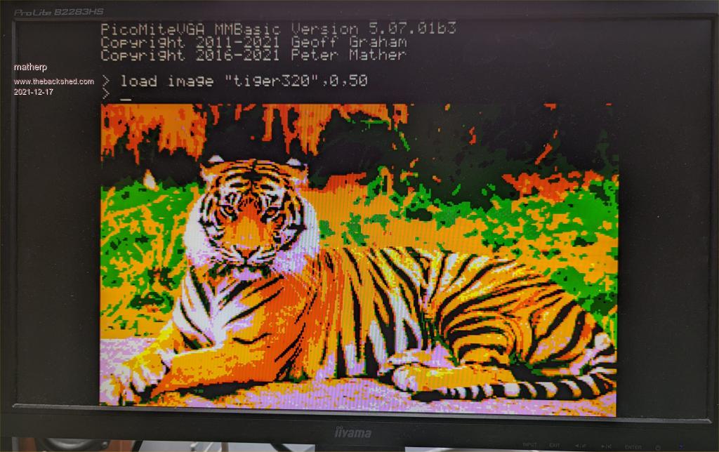 |
||||
| CaptainBoing Guru Joined: 07/09/2016 Location: United KingdomPosts: 2170 |
impressive stuff and being on the second core it has very little effect on performance(?) |
||||
| The Back Shed's forum code is written, and hosted, in Australia. | © JAQ Software 2025 |
