
|
|
Forum Index : Microcontroller and PC projects : PicoMite VGA Edition PCB - release version
| Author | Message | ||||
palcal Guru Joined: 12/10/2011 Location: AustraliaPosts: 1804 |
From the BOM Farnell/Element14 dont seem to stock either of these parts anyone found a suitable replacement. "It is better to be ignorant and ask a stupid question than to be plain Stupid and not ask at all" |
||||
| al18 Senior Member Joined: 06/07/2019 Location: United StatesPosts: 175 |
Mouser has over 3000 in stock in the US |
||||
| palcal Guru Joined: 12/10/2011 Location: AustraliaPosts: 1804 |
The freight from USA to Australia is too much. $20 or more. I can probably source a SMD device that I could solder in, I haven't checked yet just thought someone may have a through hole replacement. Edited 2022-04-20 13:24 by palcal "It is better to be ignorant and ask a stupid question than to be plain Stupid and not ask at all" |
||||
| Turbo46 Guru Joined: 24/12/2017 Location: AustraliaPosts: 1593 |
2n7000 can be used. Altronics and Jaycar both have them but note the orientation is different. Bill Keep safe. Live long and prosper. |
||||
| palcal Guru Joined: 12/10/2011 Location: AustraliaPosts: 1804 |
Thanks, Bill. "It is better to be ignorant and ask a stupid question than to be plain Stupid and not ask at all" |
||||
| palcal Guru Joined: 12/10/2011 Location: AustraliaPosts: 1804 |
I ordered the SD card breakout board from Element14/Farnell part no. 279-9953 It is different to the one shown in the photos. I can't read the silk screen on matherp's photo and the scematic in the ZIP file is .sch format that I can't open. Here is a picture of what I have. I think I will have to offset it but do the pins match up. There was no photo on the Element14 site so I was flying blind. 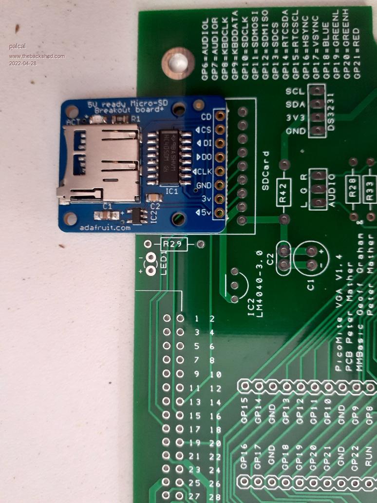 Edited 2022-04-28 14:48 by palcal "It is better to be ignorant and ask a stupid question than to be plain Stupid and not ask at all" |
||||
| Volhout Guru Joined: 05/03/2018 Location: NetherlandsPosts: 3551 |
Hi Pascal, Your sd card board is capabele of 5v. The board that Peter designed is 3.3v So you have the wrong board. But you may be able to get it to workshop by tying 5v and 3.3v pins together to 3.3v. And you may have to swap pins in the Option sd card definition. Volhout PicomiteVGA PETSCII ROBOTS |
||||
| Turbo46 Guru Joined: 24/12/2017 Location: AustraliaPosts: 1593 |
I got the one specified from Core Electronics. The pin layout is different and yours has a voltage regulator and level shifting which are not needed for Peter's board. There is a datasheet on the Element14 site for info on the one you have. Bill Keep safe. Live long and prosper. |
||||
| palcal Guru Joined: 12/10/2011 Location: AustraliaPosts: 1804 |
I have an account at Core Electronics will order from them. Thanks "It is better to be ignorant and ask a stupid question than to be plain Stupid and not ask at all" |
||||
Chopperp Guru Joined: 03/01/2018 Location: AustraliaPosts: 1032 |
Out of stock at CORE ATM Did you get the last one? . Edited 2022-04-28 18:27 by Chopperp ChopperP |
||||
| Amnesie Guru Joined: 30/06/2020 Location: GermanyPosts: 382 |
I am using this Adafruit Sd Breakout on ALL my picoMite builts. It works perfectly with 5V directly, since it has own level shift but it also works via 3V3 on the corresponding pin. In my opinion this is the ultimate breakout because it is ready for every voltage. Of course it is a slightly different pinout than the black (3v3 only) version for which the original picoMite VGA PCB was desigend for. So in short: the Adafruit blue version does work, but it won't fit the pinout on the board. Greetings Daniel |
||||
| palcal Guru Joined: 12/10/2011 Location: AustraliaPosts: 1804 |
Yes must have got the last one. @ Amnesie, thanks for that at least it is not a loss. "It is better to be ignorant and ask a stupid question than to be plain Stupid and not ask at all" |
||||
| Volhout Guru Joined: 05/03/2018 Location: NetherlandsPosts: 3551 |
Pascal, I was impatient.... 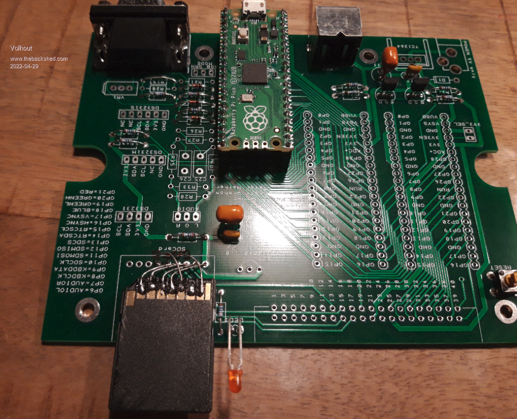 PicomiteVGA PETSCII ROBOTS |
||||
| palcal Guru Joined: 12/10/2011 Location: AustraliaPosts: 1804 |
I think we have all done wiring like that at some time. Edited 2022-04-29 06:45 by palcal "It is better to be ignorant and ask a stupid question than to be plain Stupid and not ask at all" |
||||
| Turbo46 Guru Joined: 24/12/2017 Location: AustraliaPosts: 1593 |
One way to use a different breakout would be to make a carrier board out of strip board which will fit the mounting for the specified board and fit the alternative board on top of that with the cross patching done on the strip board. That will allow you to fit the correct one later if you want. Bill Keep safe. Live long and prosper. |
||||
| Volhout Guru Joined: 05/03/2018 Location: NetherlandsPosts: 3551 |
I think I am confused. When I look at the board layout in the first post of this thread, I can clearly see that 3.3V is routed to pin 25 (or 26 when the pin numbers are mirrored). In this drawing it is on pin 36. Is the board layout in the first post not the last layout ? PicomiteVGA PETSCII ROBOTS |
||||
| matherp Guru Joined: 11/12/2012 Location: United KingdomPosts: 8592 |
No, you have spotted a complete f-up that for reasons unknown nobody else has seen before. Pins 21-40 are all completely wrong on the edge connector. I'll post a revised version once I fix it |
||||
| Volhout Guru Joined: 05/03/2018 Location: NetherlandsPosts: 3551 |
Peter, Not sure if it pays off to change the board layout in this phase, unless you have other reasons to do so. Maybe we should just document what it is, and leave it at that. The early adopters all have this version. And it is unsure how many will build the new version and throw away the old. So you end up with a mix best case. Or you spend a lot of time and no-one uses it. It feels a bit like the CMM2 revision 1 and revision 2 incompatibility. PicomiteVGA PETSCII ROBOTS |
||||
| robert.rozee Guru Joined: 31/12/2012 Location: New ZealandPosts: 2290 |
i believe there are already multiple 40-pin connector pin layouts for the various pico carrier boards. cheers, rob :-) |
||||
| JohnS Guru Joined: 18/11/2011 Location: United KingdomPosts: 3661 |
I'm confused too - what is the layout for the current connector? (on Peter's board) John |
||||
