
|
|
Forum Index : Microcontroller and PC projects : PicoMite VGA Edition PCB - release version
| Author | Message | ||||
| Volhout Guru Joined: 05/03/2018 Location: NetherlandsPosts: 3586 |
On my board (V1.4 I got from Turbo46) the pinning is (seen from front of connector) Upper row GP1 GP2 GP4 GND GP7 GP9 GP10 GP12 GND GP15 SYS ENA ADC GND GP26 GP22 GP21 GP19 GND GP16 Lower row GP0 GND GP3 GP5 GP6 GP8 GND GP11 GP13 GP14 BUS GND 3V3 GP28 GP27 RUN GND GP20 GP18 GP17 Indeed, the left half is pin number identical to the pico, but the right side seems in inverse order. Maybe that is becuase the pin counting on the pico goes round (40 is next to 1) where as connectors count in rows (1 is next to 2/3, and 40 next to 39/38) I hope this helps. I will try to make a sticker for my unit for ease of connecting. Up to now I had a bare board and I connected to the 2 pico shadow footprints that had silkscreen adjacent the pins. Now I finally came to putting it into a housing, and then ran into this problem. Which is not a problem now I know... Volhout Edited 2022-06-04 22:23 by Volhout PicomiteVGA PETSCII ROBOTS |
||||
| phil99 Guru Joined: 11/02/2018 Location: AustraliaPosts: 1813 |
" Which is not a problem now I know..." Indeed, if a different pin sequence is required for a particular device an adapter cable can be made. |
||||
| Volhout Guru Joined: 05/03/2018 Location: NetherlandsPosts: 3586 |
Finally the box arrived and the bare pico board is mounted. My dev. setup... 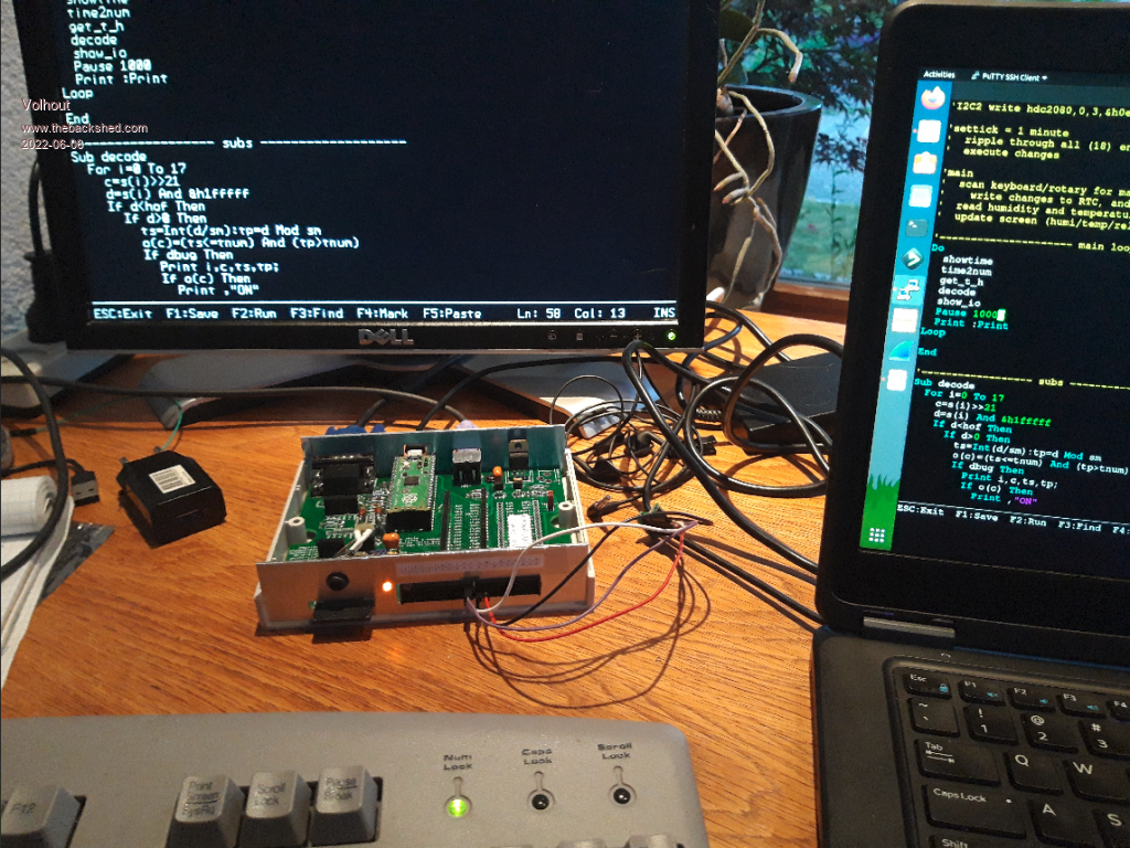 close up (SSTV interface removed from shadow pico socket) 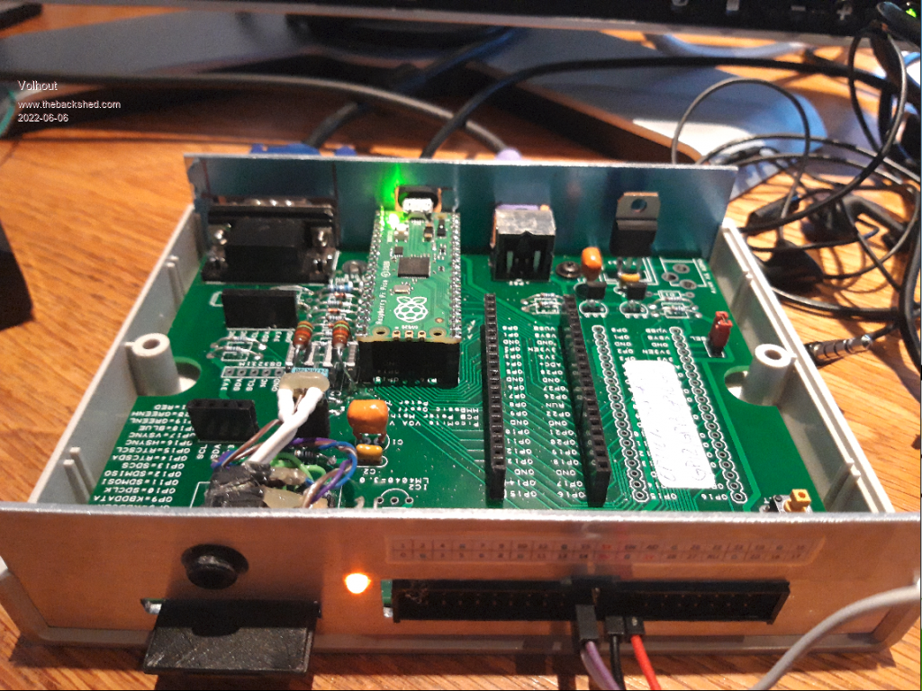 The linear regulator seems reverse, but I only had a LM1086-3V3 in my toolbox. I did separate the VGA signals from the shadow sockets and the 40pin header to improve video quality. The audio filter is an idea from MIXTEL90, using inductors, to get better frequency response and 44kHz reduction. This week my RTC will arrive.... Volhout Edited 2022-06-06 06:49 by Volhout PicomiteVGA PETSCII ROBOTS |
||||
| Volhout Guru Joined: 05/03/2018 Location: NetherlandsPosts: 3586 |
@ Peter, This is the alternative for the inductor based filter. 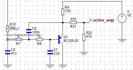 Resistor R22 is only needed to limit the output level to the level similar to the level that your 1.4 board outputs. For headphones it is not needed. Most audio amplifiers may not need it. The transistor is not critical, it can be any PNP, as long as the pinout is right. BC558, BC327 -or- the mirrored pinout 2N3906/2N2907. It's only drawback is 5V. What I like is that it can also be fully SMT. Harm Edited 2022-06-13 19:48 by Volhout PicomiteVGA PETSCII ROBOTS |
||||
| Mixtel90 Guru Joined: 05/10/2019 Location: United KingdomPosts: 5768 |
That configuration still gives me the creeps when you feed it from a device that can't stand more than 3.6V on its pins according to spec. :( If the pin is OFF and the 470R isn't fitted (or headphones connected) there is about 4.3V on it via the forward-biased emitter-base diode, albeit a bit current limited by R7, R8, R9 & R10. With the 470R connected that drops to about 3.75V. That might be survivable, but it's still higher than 3V3+Vf of a schottky diode. Mick Zilog Inside! nascom.info for Nascom & Gemini Preliminary MMBasic docs & my PCB designs |
||||
| Volhout Guru Joined: 05/03/2018 Location: NetherlandsPosts: 3586 |
@Peter, For the new revision of the VGA demo board, I would like to suggest following. 1/ Video On MY monitor the picture quality is not degrading in any way if I simplify the RGB interface to: GP21 -------- 270 ohm ---------- R GP20 -------- 390 ohm ---+------ G GP19 -------- 820 ohm ---+ GP18 -------- 270 ohm ---------- B No diodes, not potmeter 2/ Audio If you want the widest audio spectrum the previously discussed filter is what I can propose (up to 19kHz -3dB). The 150 ohm is perfectly OK, even 100 ohm works as a charm (no distortion)..But 100 ohm degrades the spectrum. 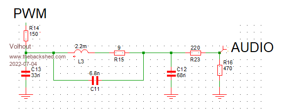 However.... My personal preference is to limit the bandwidth to 12kHz. Honestly, my hearing is not the best in the world, I am anyway deaf above 15kHz. With this filter you do not need to terminate, and the 44kHz rejection is around 10dB better even. Because of the lower cut-off you also suffer less from mirror images. The circuit can be the same as above, only values differ. 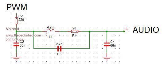 Additional benefit: it does not need the 220 ohm and 470 ohm terminating it. The frequency spectrum remains very acceptable over loads. The inductor designed for (Mick prefers R&S because lower shippig cost, maybe you do to (in UK)) 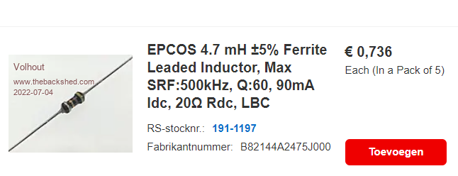 Regards, Volhout PicomiteVGA PETSCII ROBOTS |
||||
| Mixtel90 Guru Joined: 05/10/2019 Location: United KingdomPosts: 5768 |
Looks good! :) I think I'll put both of those ideas onto the next PicoGAME before it's final release. I like the idea of being able to fit alternative audio components into the same circuit as some will prefer a more hi-fi output and others will just want game sounds. I'm currently wondering if it'll be Version 1.5 or Version 2.0. :) Mick Zilog Inside! nascom.info for Nascom & Gemini Preliminary MMBasic docs & my PCB designs |
||||
| Volhout Guru Joined: 05/03/2018 Location: NetherlandsPosts: 3586 |
Hi Mick, Peter, If you make a layout of the board, please take care that these inductors are not too close to each other. They are not magnetically shielded, and couple magnetic field when right adjacent in the layout. Maybe by placement of components between them you can prevent this. 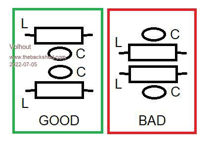 PicomiteVGA PETSCII ROBOTS |
||||
| Volhout Guru Joined: 05/03/2018 Location: NetherlandsPosts: 3586 |
@Peter Some other notes for the pico VGA board release 2.0 1/ Since VGA is THE feature of this board, I would suggest to cut the VGA connections from the main pico to the shadow footprints and the 40 pin header. Especially when you plug in a ribbon cable into the 40 pin connector you start seeing artefacts in the video. You can leave the connection between the 2 shadow footprints intact (this may come in handy if you put a second pico in), as well as the 40 pin header. Just cut of the live video signals and syncs from it. 2/ The TC1264 footprint may get an alternate footprint (i.e. LM1086-33 and LM1117-33). For the rest I have found not obstacles in building it (except I did not purchase the correct SD card header, and hand wired a SD-uSD convertor as a uSD connector on the board. But that was pure me .. ordering the wrong part. Volhout PicomiteVGA PETSCII ROBOTS |
||||
| Bleep Guru Joined: 09/01/2022 Location: United KingdomPosts: 414 |
Hi Volhout, Just to be sure, the resistor R4 (20 Ohms)in the above circuit diagram, is that an actual resistor, or is it showing the resistance of the inductor, so not a separate component? Thanks Kevin. |
||||
| Mixtel90 Guru Joined: 05/10/2019 Location: United KingdomPosts: 5768 |
It's the resistance of the inductor, not a separate one. It's needed for the simulation. Mick Zilog Inside! nascom.info for Nascom & Gemini Preliminary MMBasic docs & my PCB designs |
||||
| Volhout Guru Joined: 05/03/2018 Location: NetherlandsPosts: 3586 |
@Kevin, As Mick said, it is the resistance of the thin copper wire that is used to wind the inductor. It is only needed for the simulation. I was to lazy to remove the part from the picture. Sorry. Volhout PicomiteVGA PETSCII ROBOTS |
||||
| matherp Guru Joined: 11/12/2012 Location: United KingdomPosts: 8604 |
 New version 1.6 of the PCB which I will get made and then release the gerbers and design files. Changes: Option for LM1117 regulator SDcard swapped for the "standard" Maximite version (same as Geoff's PicoMiteVGA PCB) Revised audio filter as per Volhout (thanks) Revised VGA I/F using just 4 resistors and no diodes 40 way connector now wired correctly (pins 21-40 were wrong) Pic omits the GND plane so lots of GND wires appear unconnected Schematic VGAMite - Project.pdf |
||||
| matherp Guru Joined: 11/12/2012 Location: United KingdomPosts: 8604 |
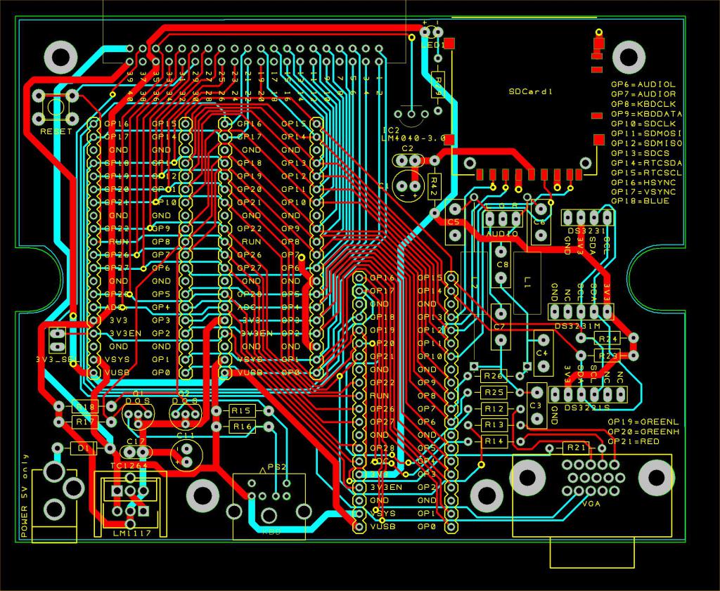
Here is the "final" version of the PCB. Cost GBP7.42 for 5 boards from JLC (+postage). To get boards made just drop the 1.7 zip onto the web page at JLC - as easy as that. 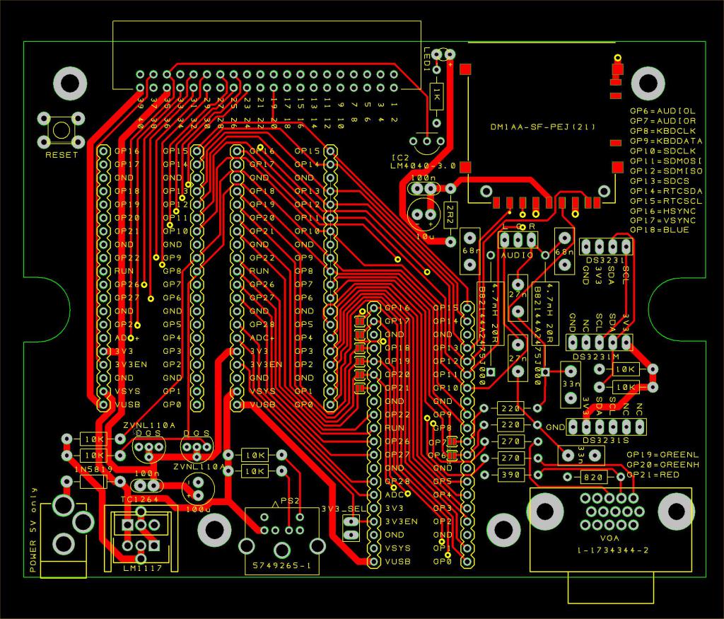 No BOM as all the non standard components are labelled on the silkscreen together with the values for the resistors and capacitors Changes: Option for LM1117 regulator SDcard swapped for the "standard" Maximite version (same as Geoff's PicoMiteVGA PCB) Revised audio filter as per Volhout (thanks) Revised VGA I/F using just 4 resistors and no diodes 40 way connector now wired correctly (pins 21-40 were wrong) By default the VGA and audio pins are not connected to the two Pico additional footprints or the edge connector. Connection can be made using a solder blob on the shorting links Traces re-routed to improve signal quality for audio and VGA Schematic VGAMite - Project.pdf Gerbers VGAMite V1.7.zip Design files VGAMite.zip 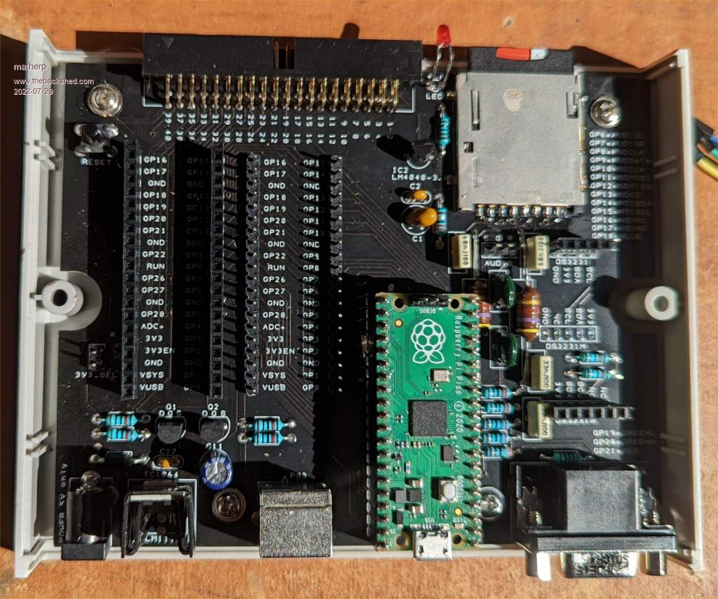 Edited 2022-07-29 20:08 by matherp |
||||
| Rickard5 Guru Joined: 31/03/2022 Location: United StatesPosts: 328 |
is there a Measured drawing for the front and back panel ? I turned the volume on the monitor to max and could hear sound. Thanks Stanleyella |
||||
| Volhout Guru Joined: 05/03/2018 Location: NetherlandsPosts: 3586 |
@Peter, Errata: the value of C7 and C8 must be 2.7nf, not 27nf. Regards, Volhout PicomiteVGA PETSCII ROBOTS |
||||
| matherp Guru Joined: 11/12/2012 Location: United KingdomPosts: 8604 |
Thanks. I've updated the silkscreen in the attached VGAMite V1.7.zip |
||||
| JohnS Guru Joined: 18/11/2011 Location: United KingdomPosts: 3677 |
In case there's a further update, the schematic could do with changing, too. BTW a searchable PDF would be good, if easy enough to create. John |
||||
| scruss Regular Member Joined: 20/09/2021 Location: CanadaPosts: 83 |
Can you please provide a BOM as text? For $reasons, if it's not machine readable text, I can't read it. I could try to parse all the squinty little lines on the schematic PDF, but they're not text either. Also, what are the optional solder links on the board for? (like the ones by GP6 and GP7). This board isn't very searchable, so it's not obvious if you've ever described what they do. Also, I see there's a nice stereo audio out: what's it typically feed into? Headphones? Speaker? Amp? Is that one or both power regulators required? I just got a set of PCBs made (purple!). Just hope I can find some of the connectors, as last time I looked they were unobtainium |
||||
| JohnS Guru Joined: 18/11/2011 Location: United KingdomPosts: 3677 |
A work around: In duckduckgo (or google): site:www.thebackshed.com/forum then here put what you want to search for John |
||||
