
|
|
Forum Index : Microcontroller and PC projects : PicoMite VGA check
| Page 1 of 2 |
|||||
| Author | Message | ||||
| hitsware2 Guru Joined: 03/08/2019 Location: United StatesPosts: 719 |
VGA5.07.03R-C10.UF2 O.K........ got a gender bender Is this : GP16 connect to VGA socket pin 13 GP17 connect to VGA socket pin 14 GP22 connect to VGA Socket 1, 2, or 3 via 220ohm resistor Connect 1n4148 diode anode to VGA socket pin 1,2,or 3. Connect 1N4148 cathode (bar end) to GND Connect GND to VGA socket pins 5,6,7,8,10 Still correct wiring ? Do not have to have PS2 keyboard , right ? VGA monitor should work in same fashion as OLED or ? I am getting a signal ( screen goes dark ) , but no picture ...... ????? ALSO ! Minicom terminal screen acts as if option display is not set for 24 , but ' option display 24 ' gives error ? my site |
||||
| phil99 Guru Joined: 11/02/2018 Location: AustraliaPosts: 2620 |
GP20 supplies the luminance signal for monochrome not GP22, all else is ok. The keyboard is optional, as console is normal USB. Works fine with TeraTerm, have not tried Minicom. Most PS/2 keyboards will run off 3.3V so can connect straight to the Pico. Usually no pullup resistors are needed, so it is a piece of cake if you have one of them. From Addendum to PicoMite Manual VGA Wiring pin GP16 to VGA pin 13 (HSYNCH) pin GP17 to VGA pin 14 (VSYNCH) pin GP18 220R to VGA pin3 (BLUE). 1n4148 from pin 3 , cathode to GND pin GP19 R5 - see diagram below (GREEN LSB) pin GP20 R6 - see diagram below (GREEN MSB / mono VGA out)<<<<<<<<<<<<<<<<<<<<<<< pin GP21 220R to VGA pin2 (RED). 1n4148 from pin 1, cathode to GND Connect GND to VGA socket pins 5,6,7,8,10 OPTION SYSTEM SPI is disabled on the VGA version. PS2 Keyboard wiring IMPORTANT use level conversion between the Pico pins and the PS2 socket or run the keyboard at 3.3V pin GP8 to PS2 socket CLOCK pin via level converter pin GP9 to PS2 socket DATA pin via level converter VBUS to PS2 socket +5V GND to PS2 socket GND To enable the PS2 Keyboard use OPTION KEYBOARD xx where xx can be any one of US/FR/GR/IT/BE/UK/ES to select the language To disable the keyboard use OPTION KEYBOARD NO_KEYBOARD SDcard syntax OPTION SDCARD CSpin, CLKpin, MOSIpin, MISOpin Edited 2022-01-10 12:04 by phil99 |
||||
| hitsware2 Guru Joined: 03/08/2019 Location: United StatesPosts: 719 |
Thank You ! .... Not at all what I was expecting , though . I anticipated the vga screen would act in the same way as a lcd display . ( respond to the program , but not show the ide ) Instead , the ide screen comes on as soon as the Pico boots. The only thing Minicom does is connect the keyboard . Still perhaps usefull if I can increase the font size enough ..... my site |
||||
| matherp Guru Joined: 11/12/2012 Location: United KingdomPosts: 10251 |
You can stop output to the VGA by using OPTION LCDPANEL NOCONSOLE then it will act like a LCD with only drawing commands showing. If you do this at the command prompt it will be permanent - use OPTION LCDPANEL CONSOLE to get it back). If you do it in a program it will not be stored and on reboot the console will re-appear. Best thing is to do something like this Option break 4 On key 3,exitint Option lcdpanel noconsole Do :Loop ' Sub exitint Option break 3 Option lcdpanel console 1 '1 if mono, use 7 if colour End End Sub Edited 2022-01-11 05:28 by matherp |
||||
| hitsware2 Guru Joined: 03/08/2019 Location: United StatesPosts: 719 |
Yes ! ....  If I should decide to use the vga console , can I increase the font size ? And ( while You are being so kind )  Do You know how to wire for the brightest possible white trace ? my site |
||||
| phil99 Guru Joined: 11/02/2018 Location: AustraliaPosts: 2620 |
"Do You know how to wire for the brightest possible white trace ?" Just remove the diode. The monitor will limit the peak brightness to its own maximum. The Pico can't supply enough current for white on its own. Add a general purpose NPN transistor (eg PN100) with collector to +5V**, base to GP20 and emitter to VGA pins 1,2,3 in parallel via a 100 ohm resistor. EDIT ** (or +3.3V - less risky in case of a wiring error, image might not be quite as sharp as with 5V) Edited 2022-01-11 07:09 by phil99 |
||||
| hitsware2 Guru Joined: 03/08/2019 Location: United StatesPosts: 719 |
Dim v(200) ADC open 500000,1 Do CLS ADC start v() For x%= 0 To 200 Pixel x%+400,(200*v(x%))-200 Next x% Pause 200 Loop Interestingly , ' ADC START ' kills the VGA ...... my site |
||||
| matherp Guru Joined: 11/12/2012 Location: United KingdomPosts: 10251 |
Good one. You've found a bug in the SDK - will fix |
||||
| X2themax Newbie Joined: 10/12/2021 Location: GermanyPosts: 11 |
Hi there ! First of all, thank you for this great project! The work that you all put into the Pico Mite is really enormous. I think it's great to have a 5Euro BASIC interpreter computer with MM-Basic. I have already built both versions of the Pico and have a few questions about the VGA version. (...and possibly a few ideas) I do not understand the current structure with the colour correction. Why do we need a green LSB and MSB signal ? Is it right that we have only 8 colours ? 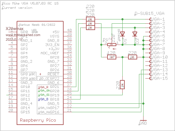 I figured out, that regular 220 ohm resisors and diodes are working very well for an acceptable VGA output with a good white balance: 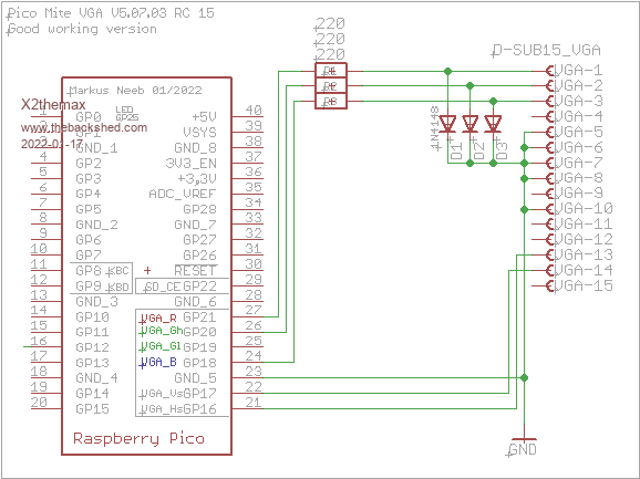 Now my idea based on an intensity signal like the VDC of a commodore 128 with 16 colours: 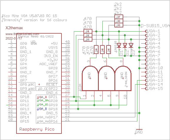 In this version 3 AND gates are combining a intensity signal with each colour signal go get 2 shades of the same colour. What are you thinking about it ? Best regards form germany and sorry for my poor english language. Markus |
||||
| matherp Guru Joined: 11/12/2012 Location: United KingdomPosts: 10251 |
Markus The VGA code uses 4-bits for each pixel. I have called this RGB121 and it gives 16 colours if wired correctly. However, each "bit" could be connected in any way you like e.g 16-level greyscale using a 4-bit R2R DAC. The firmware provides named colours that can be used for all 16 possible outputs and these represent the actual colours if wired RGB121. #define WHITE RGB(255, 255, 255) //0b1111 #define YELLOW RGB(255, 255, 0) //0b1110 #define LILAC RGB(255, 128, 255) //0b1101 #define BROWN RGB(255, 128, 0) //0b1100 #define FUCHSIA RGB(255, 64, 255) //0b1011 #define RUST RGB(255, 64, 0) //0b1010 #define MAGENTA RGB(255, 0, 255) //0b1001 #define RED RGB(255, 0, 0) //0b1000 #define CYAN RGB(0, 255, 255) //0b0111 #define GREEN RGB(0, 255, 0) //0b0110 #define CERULEAN RGB(0, 128, 255) //0b0101 #define MIDGREEN RGB(0, 128, 0) //0b0100 #define COBALT RGB(0, 64, 255) //0b0011 #define MYRTLE RGB(0, 64, 0) //0b0010 #define BLUE RGB(0, 0, 255) //0b0001 #define BLACK RGB(0, 0, 0) //0b0000 So you can use these as constants in a program and name the constant however you like depending on how you physically connect the pins. e.g. DIM integer greyscale[15] greyscale(0)=rgb(black) greyscale(1)=rgb(blue) .... greyscale(15)=rgb(white) |
||||
| JohnS Guru Joined: 18/11/2011 Location: United KingdomPosts: 4038 |
Yes. Other names would make sense with your idea. John |
||||
| X2themax Newbie Joined: 10/12/2021 Location: GermanyPosts: 11 |
Hi Peter, thank you for your fast response. Wow cool, that makes sense !  OK I didn't know that and at the same time I had made a circuit error on my breadboard.  I will try it right away. Thank you and best regards Markus |
||||
| phil99 Guru Joined: 11/02/2018 Location: AustraliaPosts: 2620 |
One possible way to map RGIB(1,1,1,1) (untested) Re-map RGB(1,2,1) VGA to RGIB(1,1,1,1) Colour to Intensity Mapped Display pin(GP19) Colour white 0 lilac yellow 0 brown magenta 0 magenta red 0 red cyan 0 cerulean green 0 midgreen blue 0 blue black 0 black white 1 white yellow 1 yellow magenta 1 fuchsia red 1 rust cyan 1 cyan green 1 green blue 1 cobalt black 1 myrtle DIM integer WhiteD(1) : WhiteD(0) = RGB(lilac) : WhiteD(1) = RGB(white) DIM integer yellowD(1) : yellowD(0) = RGB(brown) : yellowD(1) = RGB(yellow) DIM integer magentaD(1) : magentaD(0) = RGB(magenta) : magentaD(1) = RGB(fuchsia) DIM integer redD(1) : redD(0) = RGB(red) : redD(1) = RGB(rust) DIM integer cyanD(1) : cyanD(0) = RGB(cerulean) : cyanD(1) = RGB(cyan) DIM integer greenD(1) : greenD(0) = RGB(midgreen) : greenD(1) = RGB(green) DIM integer blueD(1) : blueD(0) = RGB(blue) : blueD(1) = RGB(cobalt) DIM integer blackD(1) : blackD(0) = RGB(black) : blackD(1) = RGB(myrtle) ' usage: ColourD(Intensity) where Colour to Display = ColourD & Intensity = 0 or 1 = GP19 Edited 2022-01-18 17:32 by phil99 |
||||
| X2themax Newbie Joined: 10/12/2021 Location: GermanyPosts: 11 |
Hi, it works perfectly. I have loaded this little Image: RGB-Test.zip ...and it works !  I find it interesting how the image routine quantizes the image. I guess Phil's idea of a RGIB() command is not bad.  |
||||
| lizby Guru Joined: 17/05/2016 Location: United StatesPosts: 3363 |
Great, but why not just show us the image rather than make us download the file, unzip it, and then, when I double-click on it, get "rgb.bmp It appears that we don't support this file format", or when I try to open it with PaintShopPro, get  PicoMite, Armmite F4, SensorKits, MMBasic Hardware, Games, etc. on fruitoftheshed |
||||
| Mixtel90 Guru Joined: 05/10/2019 Location: United KingdomPosts: 7879 |
Irfanview has no problem in opening either image, even direct from the zip file. Mick Zilog Inside! nascom.info for Nascom & Gemini Preliminary MMBasic docs & my PCB designs |
||||
| phil99 Guru Joined: 11/02/2018 Location: AustraliaPosts: 2620 |
Loading an image directly into the Pico won't give the correct RGIB rendering as the built in image viewer is still decoding it as RGB(1,2,1). It will be necessary to pre process images in a suitable image editor to change the colour palate to make them decode correctly on the Pico despite it not having the correct decoder for RGIB hardware. I think the re-mapping, in a previous post, of colours only works for graphics and text generated by the Pico not loaded images. Edit. The mapping in my previous post was done whilst half asleep. Though correct it is poorly thought out. Here it is again. DIM integer whiteD(1) = (&HFF80FF,&HFFFFFF) DIM integer yellowD(1) = (&HFF8000,&HFFFF00) DIM integer magentaD(1) = (&HFF00FF,&HFF40FF) DIM integer redD(1) = (&HFF0000,&HFF4000) DIM integer cyanD(1) = (&H0080FF,&H00FFFF) DIM integer greenD(1) = (&H008000,&H00FF00) DIM integer blueD(1) = (&H0000FF,&H0040FF) DIM integer blackD(1) = (&H000000,&H004000) . Edited 2022-01-19 15:54 by phil99 |
||||
| X2themax Newbie Joined: 10/12/2021 Location: GermanyPosts: 11 |
OK -sorry- I will check it ! Here is the test image rgb.bmp: 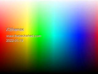 Ok... XnView opens the picture without any problems. It is a reguar RGB-Bitmap and the Pico load this picture correct. If you have any problems I try to post it again. |
||||
| X2themax Newbie Joined: 10/12/2021 Location: GermanyPosts: 11 |
You should now see the following on the Pico Mite:  Now all 16 colours are displayed. |
||||
| X2themax Newbie Joined: 10/12/2021 Location: GermanyPosts: 11 |
I forgot the following: If you assign the GPIOs wrong, the two shades of green are reversed and the picture makes no sense! It should work as above if you coose the right GPIOs. The Second Image shoult be displayed like this:  I wish you all success ! |
||||
| Page 1 of 2 |
|||||
| The Back Shed's forum code is written, and hosted, in Australia. | © JAQ Software 2025 |
