
|
|
Forum Index : Microcontroller and PC projects : PicoMite VGA check
| Author | Message | ||||
| robert.rozee Guru Joined: 31/12/2012 Location: New ZealandPosts: 2437 |
someone might care to give this a try, digital RGBI to analog RGB: 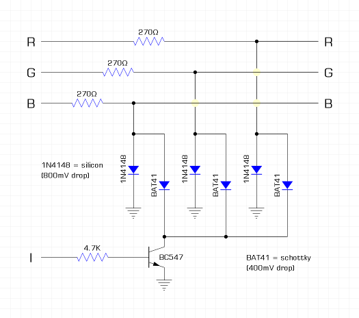 note - the function of I is inverted i have NOT tried the circuit, but believe it should give good results. but, of course, will not solve the problem with loading images. perhaps an OPTION could be added to the firmware to select between RGGB and RGBI. this option could also, at the same time, switch between two sets of colour constant names. cheers, rob :-) Edited 2022-01-19 22:46 by robert.rozee |
||||
| matherp Guru Joined: 11/12/2012 Location: United KingdomPosts: 10241 |
What's the voltage across a BJT transistor when it is turned on? Seems to me you will be pulling the BAT141 to 0.7V i.e. zero impact |
||||
| robert.rozee Guru Joined: 31/12/2012 Location: New ZealandPosts: 2437 |
you are confusing Vbe with Vce. Vce(sat) of a BC547 is around 90mV. there may be better choices that yield an even lower value. as i said, i've not tried the circuit. addendum: have a dig around here: https://www.onsemi.com/products/discrete-power-modules/general-purpose-and-low-vcesat-transistors cheers, rob :-) Edited 2022-01-19 23:26 by robert.rozee |
||||
| Mixtel90 Guru Joined: 05/10/2019 Location: United KingdomPosts: 7867 |
VCEsat for that transistor is 90mV typ, 250mV max. That bit's ok. The BAT41 has a Vf of about 700mV at 10mA though. I can't see this working. Also remember that once driven into saturation the transistor will take a little time to come out of it. Whether that will be an issue at this frequency I don't know. Edited 2022-01-19 23:35 by Mixtel90 Mick Zilog Inside! nascom.info for Nascom & Gemini Preliminary MMBasic docs & my PCB designs |
||||
| robert.rozee Guru Joined: 31/12/2012 Location: New ZealandPosts: 2437 |
oops, i should have selected the BAT42: https://www.vishay.com/docs/85660/bat42.pdf that will get us back to a maximum Vf of 400mV @ 10mA. it does look like there are better choices for the NPN transistor, and i could have used a much lower base resistor to help things along too. i'll let others experiment as i'm not using the VGA version myself. cheers, rob :-) Edited 2022-01-19 23:45 by robert.rozee |
||||
| X2themax Newbie Joined: 10/12/2021 Location: GermanyPosts: 11 |
Hi Mixtel90 I think lizby was right... The BMP header wasn't quite correct and Irfanview had no problems, but Gimp and Photoshop did. @robert.rozee: Peter's schematic ist working good with full 16 colours ! I corrected my files, everything should work now. Here I wrote a small UNREAL "fake" demo to demonstrate the whole thing again in a funny way. Unreal.zip Have a lot of fun ! PS: Do any of you still know the old DOS demo Unreal by Future Crew? If not watch at 7:10 : https://www.youtube.com/watch?v=VjYQeMExIwk |
||||
| lizby Guru Joined: 17/05/2016 Location: United StatesPosts: 3358 |
Once again, it's best not to make forum members unzip things except very long programs and very large images. If possible, please post images or links. You'll get more actual viewers if you don't force people to go through multiple steps, especially with zip files with unknown contents. PicoMite, Armmite F4, SensorKits, MMBasic Hardware, Games, etc. on fruitoftheshed |
||||
| X2themax Newbie Joined: 10/12/2021 Location: GermanyPosts: 11 |
... |
||||
| KD5ZXG Regular Member Joined: 21/01/2022 Location: United StatesPosts: 53 |
1N4148 clipping diodes have lower dynamic resistance than matches 75 ohm cable. It gives a good voltage, but maybe also standing waves and echos. 180 over 150 divider calculates better match to 75 w similar voltage at the far end. 270 for Green's MSB, 270 + 270 = 540 for Green's LSB, all together over 150. I've calculated even closer values if you have a stash of E96 series. 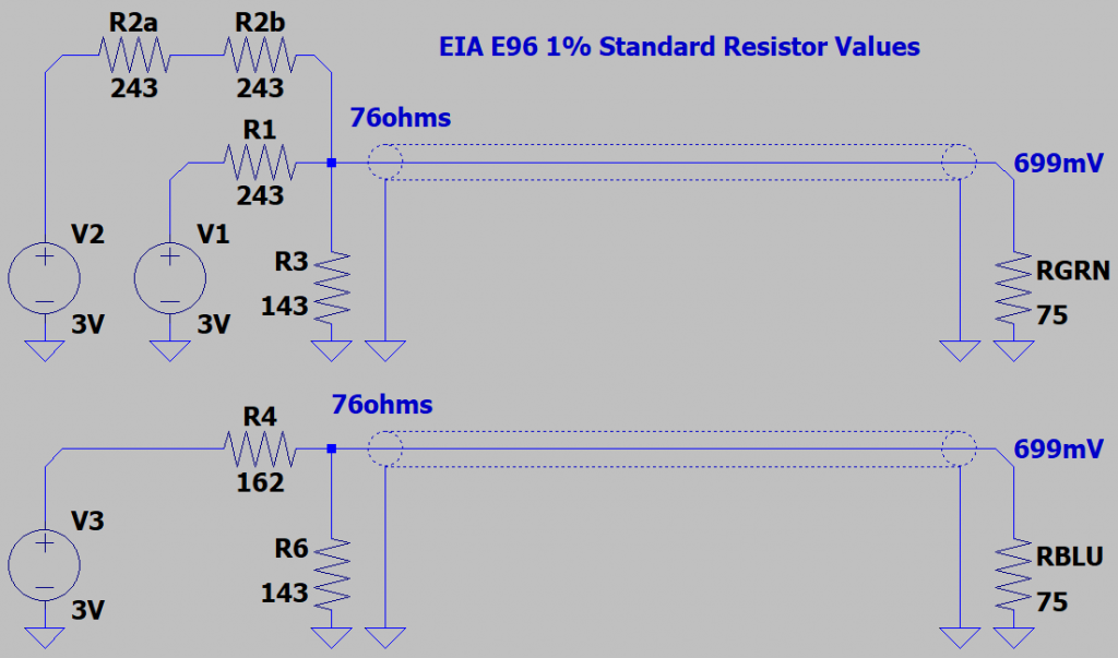 Fair warning: I've only simulated, not yet tested these values. My Pico won't output higher than 3V when driving an LED, which may not be a safe assumption it would output the same when VGA DAC is the load. I cut one end off an old VGA cable only to have trouble getting solder to wet the ground braids. Aluminum or stainless I don't know? But it's most annoying to have ruined a cable I now maybe can't use. Edited 2022-01-21 17:44 by KD5ZXG |
||||
| Mixtel90 Guru Joined: 05/10/2019 Location: United KingdomPosts: 7867 |
Crimp some Dupont pins onto the ends. They can plug into a breadboard then. There isn't much output drive available from the PicoMite pins. You need 9.3mA to drive a 75R resistor to 0.7V. If you attempt to match both ends of the cable you'll need a lot more current and the pin can't supply that even when set to full drive. If you want to match the cable properly you'll have to put an emitter follower in. Edited 2022-01-21 17:56 by Mixtel90 Mick Zilog Inside! nascom.info for Nascom & Gemini Preliminary MMBasic docs & my PCB designs |
||||
| KD5ZXG Regular Member Joined: 21/01/2022 Location: United StatesPosts: 53 |
75 ohm impedance match on the Pico end of the cable isn't the same load as 75 to GND. So current with the E96's works out to 14.3mA, which is still a bit steep. With 180 over 150, maybe about 13mA and 650mV. 270 over 1N4148 could be 8.9mA. 1mA of that bled by the diode on the near side. For 588mV into 75 at the far end. Current might necessitate less than 0.7V at the far end. Edited 2022-01-21 18:32 by KD5ZXG |
||||
| phil99 Guru Joined: 11/02/2018 Location: AustraliaPosts: 2611 |
Impedance match is only important for long cables - tens to hundreds of meters. No visible problems on short cables. Clipping diodes are only needed on very old cheap CRT monitors that have inadequate beam current limiting. I have not found a LCD monitor that can't cope with up to 1.5V. With just a 220 ohm resistor in series with the 75 ohm input, I measure a Pico pin voltage of 2.2V. This gives a pin impedance of around 150 ohms, something to add to the circuit simulation. |
||||
| Mixtel90 Guru Joined: 05/10/2019 Location: United KingdomPosts: 7867 |
It's still 75R to ground at the monitor end - or you have to assume that it is. The max current that still has a reasonable voltage (Voh>2V6) from a Pico pin is 12mA if it's been set that high. That doesn't give you much to play with at the active end. You should be able to drive a VGA input to 0.7V (or close to it) pretty easily over a normal length VGA lead though. Don't be too fussy. If you sit far enough from the monitor to need an extra long cable then you can't read it anyway. :) Peter's original scheme works nicely in real life, in spite of a nasty glitch in the middle of the R-2R ramp caused by heavy loading on the output (tested in simulation, not on a scope). These things are not generally visible. Mick Zilog Inside! nascom.info for Nascom & Gemini Preliminary MMBasic docs & my PCB designs |
||||
| The Back Shed's forum code is written, and hosted, in Australia. | © JAQ Software 2025 |
