
|
|
Forum Index : Microcontroller and PC projects : Alternative take on the 5" SSD1963 + PicoMite
| Author | Message | ||||
| Mixtel90 Guru Joined: 05/10/2019 Location: United KingdomPosts: 7867 |
I was unhappy with the location too - I've swapped the text and connector positions. Unfortunately I can't get RHS mounting holes. The board piggy-backs on the back of the display but, in order to keep the board within the cheap PCB offer, I can't use the full width. However, my board is only 75mm wide and snapping 1.6mm FR4 board over that distance is no mean feat, even when you've scored it on both sides and put one side in a vice. :) I would recommend putting a spacer on the back though, to prevent it shorting something on the back of the display. I've put a 3mm hole to use for one, it lines up with a relatively blank area of the display board so a nylon spacer should be ok. The SDcard module has a row of SMD, but they are a bypassed supply cap and 10k pullups on the signals. You can use the "pins up" version on the back of the pcb or the "pins down" version on the front. Or you can find a version with no pins and fit your own. The RTC module is also common on ebay. Edited 2022-01-15 18:52 by Mixtel90 Mick Zilog Inside! nascom.info for Nascom & Gemini Preliminary MMBasic docs & my PCB designs |
||||
| Mixtel90 Guru Joined: 05/10/2019 Location: United KingdomPosts: 7867 |
Well, I did the other end... 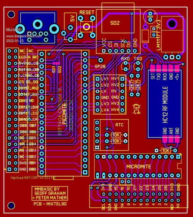 Unfortunately the HC12 has covered the "safe" hole that I'd found for a spacer. Edited 2022-01-15 22:10 by Mixtel90 Mick Zilog Inside! nascom.info for Nascom & Gemini Preliminary MMBasic docs & my PCB designs |
||||
| flasherror Senior Member Joined: 07/01/2019 Location: United StatesPosts: 159 |
Just had a thought for the RS485 PCB - you might be able to fit two RS485 header connectors instead of one to allow daisy chaining multiple boards? For the HC12 PCB I think layout for the 5 pin through hole header might be a better choice than the SMD version: 1. Can easily swap RF modules if required 2. Modules can be preprogrammed with channel etc on a test jig PCB and simply swapped to actual nodes. This might be important as there have been fake HC12 that use different crystal, preventing communication between real/fake HC12s. Didn't mean to cause extra work, never occurred to me that you might layout for SMD rather than header connector so apologies for not specifying. Of course, doing a separate PCB for HC12 probably allows space to throw in JDY40/HC12 RF modules (both same pinout) and CDEBYTE 7-pin modules to allow flexibility in RF module selection. Let me know if you want to implement these, I can post my notes for those modules. Edited 2022-01-15 22:59 by flasherror |
||||
| Mixtel90 Guru Joined: 05/10/2019 Location: United KingdomPosts: 7867 |
You shouldn't daisychain RS485 like that. Common the loop wires in the same plug-in connector so that when you unplug a node the rest of the loop stays running. Alternatively, connect the loop to a local box and plug the node into that on a short stub (not as good - it can sometimes cause all sorts of echoes on the loop and reduce the range). I'll consider a header type for the HC12, but the SMD version will probably be more stable from an RF point of view. I won't be making any of these boards anyway. As a radio amateur I know that there's enough c**p out there on the air without adding more. The only HC12 modules I can easily find that have pins are a short black version with the antenna already soldered onto one end (usually out of stock). I'm quite happy to give you the SL6 file if you want to make a version in Sprint Layout. Edited 2022-01-15 23:25 by Mixtel90 Mick Zilog Inside! nascom.info for Nascom & Gemini Preliminary MMBasic docs & my PCB designs |
||||
| flasherror Senior Member Joined: 07/01/2019 Location: United StatesPosts: 159 |
I never even heard of Sprint Layout before you mentioned you used it, but seems reasonably priced for what it does (layout only). What's the general parts library like? Does SL6 have common parts like PICs etc or do you have to use "generic" DIP28 sockets? Autorouting? (I am not good at manual routing, I always paint myself into a corner somehow). Also any annoying license/registration scheme? I hate having software locked to the PC that it's running on... I use Eagle for PCB design but always meant to check out Kicad etc. |
||||
| Mixtel90 Guru Joined: 05/10/2019 Location: United KingdomPosts: 7867 |
The library is pretty minimal, but Grogster has quite a large library that he kindly let me have a copy of. There are a few others available on the web. It's *very* easy to create your own components from scratch though, and keep them in your own libraries. The "autorouting" that it has is crude and extremely minimal. TBH I've not used it apart from just playing as the manual routing is very easy if you just keep an eye on the grid (and don't get confused between English and metric. lol) Sprint Layout won't read circuit files from anything, not even their own circuit drawing software so there's no schematic capture possible. There's no problem in running it on more than one machine. It's not locked. The file is registered to you though and your details appear every time you start it up. Just to remind you! :) There is a viewer for SL6 files and a demo version of Sprint Layout 6 on the official web site. The demo won't save anything. I've used Eagle previously. I like it but I don't like the restrictions that Autodesk put on it now. I like to be able to make boards bigger than that even if I don't actually do so. :) I've also tried KiCad but I found the learning curve very steep and making new components was a pain. DesignSpark looks more promising and I might try that before long. Mick Zilog Inside! nascom.info for Nascom & Gemini Preliminary MMBasic docs & my PCB designs |
||||
| Mixtel90 Guru Joined: 05/10/2019 Location: United KingdomPosts: 7867 |
Here's a version for the HC12 and EY-40 wireless modules. ssd1963-5in HC12 10.zip . Mick Zilog Inside! nascom.info for Nascom & Gemini Preliminary MMBasic docs & my PCB designs |
||||
| Mixtel90 Guru Joined: 05/10/2019 Location: United KingdomPosts: 7867 |
With some leverage I've managed to squeeze the ESP8266-01S in. 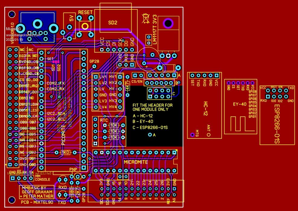 Mick Zilog Inside! nascom.info for Nascom & Gemini Preliminary MMBasic docs & my PCB designs |
||||
| lizby Guru Joined: 17/05/2016 Location: United StatesPosts: 3358 |
Nice. I can't tell for certain, but do you think you have enough capacitor to get the ESP-01 over the humps? The LM1117T is very capable, but weediness in the power supply is perhaps the biggest problem with the ESP-01. PicoMite, Armmite F4, SensorKits, MMBasic Hardware, Games, etc. on fruitoftheshed |
||||
| Mixtel90 Guru Joined: 05/10/2019 Location: United KingdomPosts: 7867 |
Hopefully. The incoming reservoir is 1000uF and the LM1117 is 800mA rated. In theory I think it should handle it, but space is very tight. lol I'm more bothered that the antenna isn't really far enough away from the ground planes. Even if it were, the board will be close to the display so that might cause problems with any module that uses a PCB antenna. The voltage on the ESP is wrong in this pic. I've shown it on 5V. :( Mick Zilog Inside! nascom.info for Nascom & Gemini Preliminary MMBasic docs & my PCB designs |
||||
| lizby Guru Joined: 17/05/2016 Location: United StatesPosts: 3358 |
Ah, +now+ I see the cap. PicoMite, Armmite F4, SensorKits, MMBasic Hardware, Games, etc. on fruitoftheshed |
||||
| KD5ZXG Regular Member Joined: 21/01/2022 Location: United StatesPosts: 53 |
Why the oddball Micromite as an I/O expander vs a second Picomite? More pins, faster, cheaper, usb bootloader... Edited 2022-01-21 18:48 by KD5ZXG |
||||
| Mixtel90 Guru Joined: 05/10/2019 Location: United KingdomPosts: 7867 |
The PicoMite only has 3 ADC inputs. I want more. :) As three of the remaining pins were those three ADCs and I needed a serial interface I'd already lost at least one of them (two for RS485). It also takes up a lot more PCB area. I wanted to keep the board small. Firstly, the price goes up when you get over 100mm x 100mm. Secondly, if you can't get all four fixing points because of the above then the best compromise is to make the board as narrow as possible. I managed to keep it to 75mm, which is still rigid for 1.6mm FR4. Speed isn't a great issue. You are controlling it over a serial interface and that's the limiting factor. Mick Zilog Inside! nascom.info for Nascom & Gemini Preliminary MMBasic docs & my PCB designs |
||||
| The Back Shed's forum code is written, and hosted, in Australia. | © JAQ Software 2025 |
