
|
|
Forum Index : Microcontroller and PC projects : MX170: PWM resolution
| Author | Message | ||||
| robert.rozee Guru Joined: 31/12/2012 Location: New ZealandPosts: 2437 |
hmmm, i am warming to the idea of directly poking the PWM registers, provided it doesn't create any glitches. this would be after configuring the pins and frequency using: PWM 1, 400, 50, 50 (assuming i'm using 2 outputs, one for coarse adjustment and the other for fine adjustment) the environment will be completely contained in a thermally insulated metal box, so all temperature changes will be extremely smooth. does anyone know what the PWM register addresses are? if they could also be read back, that would be most excellent as i could then work out a chart showing granularity versus frequency and CPU speed (perhaps a useful addition to the MMbasic manual). cheers, rob :-) Edited 2022-02-14 02:16 by robert.rozee |
||||
| Mixtel90 Guru Joined: 05/10/2019 Location: United KingdomPosts: 7877 |
Do you need the register address? Use PWM 1, 400, myvar1, myvar2 a% = PEEK(VARADDR myvar1) b% = PEEK(VARADDR myvar2) value_of_myvar1 = PEEK(INTEGER a%) to read it or POKE INTEGER a%, value_to_be_set or something along those lines... Edited 2022-02-14 02:45 by Mixtel90 Mick Zilog Inside! nascom.info for Nascom & Gemini Preliminary MMBasic docs & my PCB designs |
||||
| Tinine Guru Joined: 30/03/2016 Location: United KingdomPosts: 1646 |
That's pretty   |
||||
| matherp Guru Joined: 11/12/2012 Location: United KingdomPosts: 10250 |
and also unless I'm missing something completely wrong - just gives you the value you set in the first place. To get the register address you need to look up the datasheet and "peek(word" it. |
||||
| Mixtel90 Guru Joined: 05/10/2019 Location: United KingdomPosts: 7877 |
Why would the register change unless you'd set it? TBH I couldn't see the point in reading the PWM register. It may well be wrong. I'm no programmer. :) Mick Zilog Inside! nascom.info for Nascom & Gemini Preliminary MMBasic docs & my PCB designs |
||||
| Tinine Guru Joined: 30/03/2016 Location: United KingdomPosts: 1646 |
That's kinda what hit me, aren't you just accessing the address of the variable? But then again, isn't the PWM assigned by PPS? PIC32MX1XX_2XX_Family_Data_Sheet_61168D.pdf Craig |
||||
| Mixtel90 Guru Joined: 05/10/2019 Location: United KingdomPosts: 7877 |
The pins are set via PPS, but the registers for PWM will be decided by MMBasic. Probably using the timer registers but it doesn't have to. There don't seem to be any specific PWM devices on that chip. Mick Zilog Inside! nascom.info for Nascom & Gemini Preliminary MMBasic docs & my PCB designs |
||||
| Tinine Guru Joined: 30/03/2016 Location: United KingdomPosts: 1646 |
I wonder... Play around with various PWM settings and PEEK the registers to see which change? Registers attached, might be easier than the data sheet. Bypic registers.zip |
||||
| Volhout Guru Joined: 05/03/2018 Location: NetherlandsPosts: 5066 |
Robert, Please note that the trim input of the reference is very sensitive, and the noise filter pin of the chip is connected to the other input of the opamp inside the reference. This means you need a very good low pass filter after the pwm output. Also check: the temperature resolution of the ds18s20 is not gating for success but the absolute accuracy. Or you will have to match each individual ds18s20 with its ad587. In a process of hours calibration in a temperature chamber. Nice project btw.... PicomiteVGA PETSCII ROBOTS |
||||
| Volhout Guru Joined: 05/03/2018 Location: NetherlandsPosts: 5066 |
Robert, You may also be able to create a 16 bit dac with a 4 bit resistor dac, combined with 12 bit pwm dac. In that case you already have 24dB rejection of the pwm switch noise. Volhout. PicomiteVGA PETSCII ROBOTS |
||||
| Geoffg Guru Joined: 06/06/2011 Location: AustraliaPosts: 3285 |
I would not want to put this special feature into the standard Micromite distribution as documenting it would be a nightmare. However, here is a special version V5.05.05RR (for Robert Rozee): Micromite-V5.05.05RR.zip In the PWM command the duty cycle can be specified as a negative integer and that value will be directly loaded (as a positive number) into the OCxRS register of the output compare module without scaling or error checking. Notes: - The clock frequency for the timer is the CPU speed (normally 40MHz) for PWM frequencies 1250Hz and above or CPU speed divided by 64 for PWM frequencies less than that. - You will need to refer to the timer and output compare documentation to see what is going on: PIC32 Reference.zip - I have not fully tested this so let me know if you have any problems. Geoff Geoff Graham - http://geoffg.net |
||||
| robert.rozee Guru Joined: 31/12/2012 Location: New ZealandPosts: 2437 |
hi Geoff, many many thanks! so far it works brilliantly i've been using the following test program to verify correct operation of controller 1 at frequencies below 1250Hz: Do Input "frequency"; frequency If frequency=0 Then Exit limit=625000\frequency ' 40MHz/64 = 625000 Print frequency " Hz",, limit " steps" PWM 1, frequency, 0, 0, 0 For I=1 To limit-1 Print " " I " " Chr$(13); PWM 1, frequency, 0, 0, -I Pause 10 Next I Pause 2000 I=limit PWM 1, frequency, 0, 0, -I Print "finished" Loop for all frequencies i've tried (below 1250Hz), 625000\frequency corresponds exactly to 100% with a 40MHz CPU clock, with the pulse width variable in steps of 1.6us (1/625000). i've also used the below code to verify that at different frequencies, successive values produce a pulse width change: Sub check Do Input "frequency"; frequency If frequency=0 Then Exit Do PWM 1, frequency, -1, -1, -1 Pause Rnd*25 PWM 1, frequency, -2, -2, -2 Pause Rnd*25 Loop Until Inkey$<>"" Loop End Sub btw, the random pauses are to prevent aliasing and ensure both pulses display clearly on my scope no matter what frequency is being tested. at frequencies of 1250Hz and above i see a pulse width granularity of 25ns, as expected. the only minor 'bug' i see is that if i enter a frequency less than 20Hz, then the error message displayed is truncated: > run frequency? 10 10 Hz 62500 steps [8] PWM 1, frequency, 0, 0, 0 Error : 10 is invalid (valid is 20 to 5 > i'm guessing this clipping (at 39 characters) is common to all error messages. cheers, rob :-) Edited 2022-02-15 00:13 by robert.rozee |
||||
| Geoffg Guru Joined: 06/06/2011 Location: AustraliaPosts: 3285 |
Thanks, something I need to fix. Geoff Graham - http://geoffg.net |
||||
| robert.rozee Guru Joined: 31/12/2012 Location: New ZealandPosts: 2437 |
every DS18B20 and AD587 will be a unique pair anyway. it doesn't matter if the DS18B20 is inaccurate, just as long as the output is precise:  the trim is applied via a high-value resistor, which results in surprisingly little filtering being required. the PWM output of the MX170 controls an electronic switch that toggles between 10v and 0v. the centre of this switch is then connected to a low-value resistor (1k or so) which feeds into a filter capacitor (1uf or so). this capacitor then feeds via a high-value resistor (1M or so) to the trim pin. the trim pin is also attached to the slider of a 10k pot that is strung between 10v and 0v. first one trims the reference with the 10k pot, then you carry out the (long) digital calibration procedures. the electronic switch is usually a CMOS logic device powered from the reference voltage itself. eg, a 70C04 or similar. see, for an example: https://www.eevblog.com/forum/metrology/an-experimental-pwm-circuit-with-74hcu04/msg3921608/#msg3921608 (although in this example use of HC family limits the supply to 7v maximum. this is something i need to investigate further.) cheers, rob :-) Edited 2022-02-15 00:42 by robert.rozee |
||||
| Volhout Guru Joined: 05/03/2018 Location: NetherlandsPosts: 5066 |
Hi Robert, I hope you are not anoyed by my interest and feedback. Thank you for the explanation. I understand what you are trying to achieve. If you are running the PWM at 1250Hz to achieve 16 bit resolution (Geoff suggest). 1/ to suppress the ripple from 10V to 100mV at the 10uF cap, you need a factor 100 (40dB) reduction of pp ripple. If your goal is 10uV (1ppm) I think 100mV is too much, but opinions may vary. Anyway, you need at least 2.2k resistor to get 100mV. 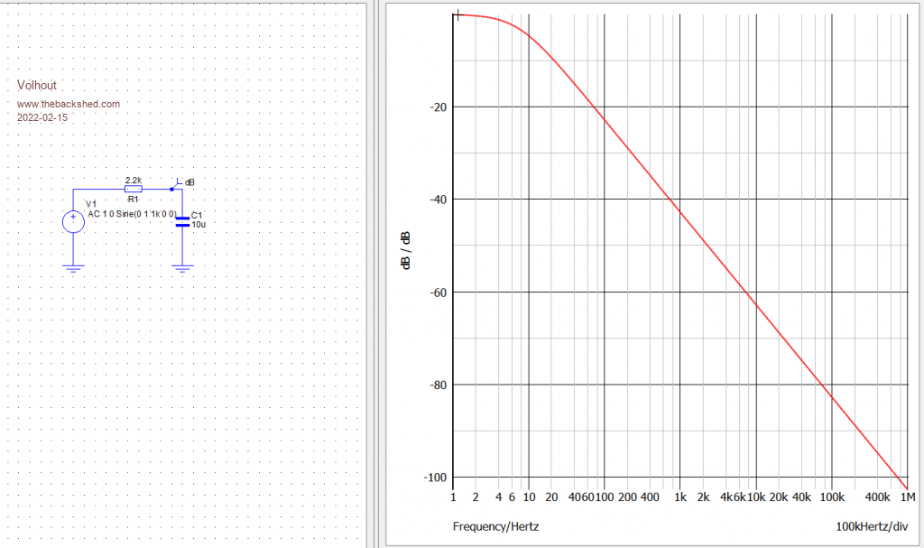 If you use 2.2k then the peak current drawn from 10V is 5mA. That will generate ripple on the 10V. Therefore it is better to buffer the 10V with a low drift opamp, and use the buffered output to power the PWM. However... If I read read the datasheet of the AD587 correctly, the tuning range from the TRIM pin is +/- 14mV. There is already a high impedance resistor inside the AD587. When the tuning range is that limitted, you van also run the PWM from a accurate 3.3V, and apply the output via a relatively high impedance resistor to the wiper of the potmeter. As long as it is high impedance with respect to the potmeter. Something like 100k. So power the MX170 from a accurate and temperature stable 3.3V (does not need to be as accurate as the AD587 itself) and use it's push-pull output to drive the RC filter directly. No need for external switches. By the way the trimpotmeter needs to have good long term stability (metal film ?). And you may already have to be carefull about the metals you use. Thermocouple voltages between solder and copper will already play a role at only few degrees temperature difference. My colleague, who has designed multimeters also suggest that when you have to use mechanical relays, use bi-stable relays, because heating of relays coil will cause thermoelectric voltages that destroy your 1ppm goal. Edited 2022-02-15 01:05 by Volhout PicomiteVGA PETSCII ROBOTS |
||||
| robert.rozee Guru Joined: 31/12/2012 Location: New ZealandPosts: 2437 |
no worries, not annoyed at all - your feedback is very much welcome and appreciated. the recommendations on the EEVblog metrology forum seem to be to keep the switching frequency relatively low. Andreas on EEVblog suggests 300Hz to aid in rejection of both 50Hz and 60Hz mains. i rather like your idea of using an opamp to buffer the 10v, conveniently at the same time it can be halved to 5v which makes using a 74HCU04 easier: 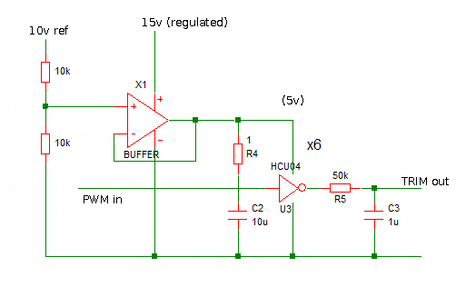 (edited from schematic in EEVblog posting linked to earlier, "TRIM out" goes to trim pin via a high-value resistor) i can always use a second PWM channel to provide a second trim voltage through an even higher feed resistor if needsbe, thereby achieving more effective bits of resolution. the schematic i borrowed above uses 50k, it just needs to be a couple of orders of magnitude less that the associated high-value resistor. remember that we are only wanting to shift the trim pin a very small amount. i would rather not use the MX170's PWM output pin to drive the resistor/capacitor directly, as there is still quite some electrical noise on the PWM pin. the use of a CMOS logic chip running from the reference voltage seems to be a trusted approach to mitigate this. 'professionals' replace trimpots with fixed-value resistors after calibration! but will address that one when i get to it. cheers, rob :-) |
||||
| Mixtel90 Guru Joined: 05/10/2019 Location: United KingdomPosts: 7877 |
Looking at Volhout's plot above, even with only 2k2/10u any noise from the MX170's PWM pin is going to be very well filtered out. The primary clock frequency is well above 1MHz, where you are already at -100dB and falling rapidly. Harmonics will be non-existent. I would suggest that if you are seeing noise on the output from the filter then it's to do with poor layout or is coming from your reference supply rather that produced by the chip. If response time isn't an issue but noise is, you could always use a 2-stage filter rather than a single RC stage. PWM is always a compromise between allowable ripple and filter response time. :) Use a good quality capacitor. (50k? What sort of new-fangled value is that? What happened to good old 47k? It'll be feeling left out ...) Mick Zilog Inside! nascom.info for Nascom & Gemini Preliminary MMBasic docs & my PCB designs |
||||
| Volhout Guru Joined: 05/03/2018 Location: NetherlandsPosts: 5066 |
In case the adjustment range on the trim pin is +/-14mV on a 10V range that is 28mV/10V = 0.003. If you are goaling for 1ppm ripple (10uV on 10V) from the PWM you need a filter that outputs max 10uV/0.003 = 3mVpp ripple at the TRIM pin. With the chosen 300Hz frequency Zc=1/(2*pi*f*c). For 10uF Zc= 53ohm. To get 3mV from 5V at the HCU04, you need 0.003/5 gain is 1/330'th Therefore the series resistor must be minimal 330x53ohm = 17k. So your 50k/10uF is fine for 300Hz. Please note that ceramic capacitors capacitance value is voltage dependent (at 12V they can be 5uF only), but with 50k you have sufficient margin. But if you want to go a certain, pick a film capacitor for that one. And maybe a 1nF ceramic parallel to make sure no high frequency passes. Another thing to think about is: If you really achieve 16 bits (1:65000) you potentially can avoid the potmeter completely, and do it all in SW. +/-14mV adjustment range at 16 bits resolution would allow you to adjust to 0.5uV steps. That should be sufficient for many applications. Nice project... Volhout PicomiteVGA PETSCII ROBOTS |
||||
| Volhout Guru Joined: 05/03/2018 Location: NetherlandsPosts: 5066 |
Hi Robert, How puzzle pieces sometimes fall into place. Studying my new challenge, and found that customer uses a 16bit DAC (DAC8531E) to generate accurate output voltages and currents... At Farnell a 6 dollar DAC.... Let's see if we can change that to PWM.... Volhout PicomiteVGA PETSCII ROBOTS |
||||
| The Back Shed's forum code is written, and hosted, in Australia. | © JAQ Software 2025 |
