
|
|
Forum Index : Microcontroller and PC projects : MX170: PWM resolution
| Author | Message | ||||
| robert.rozee Guru Joined: 31/12/2012 Location: New ZealandPosts: 2437 |
hi Volhout, i did look at using a 16-bit DAC, but could find nothing i could readily lay my hands on locally at a reasonable (ie, cheap!) price. in principal a 16-bit DAC (or indeed 2x 8-bit DACs) should be just as good as the PWM approach, if not better. i have located in my spare parts cache a tube of a dozen 74HCU04 chips, and am planning on experimenting with them shortly. i have a couple of LT1021-5 references (5 volt output) that i can pair up with a 74HCU04 directly without any need for dividing down 10v -> 5v. the LT1021-5's performance might not be ideal, but it will be a good starting point to explore with to find out what does and does not work. i've also ordered ten ADG419 analog switches, which are currently on a slow boat from china. these are the 'rolls royce' solution: can switch up to 12v, 5v control logic input, break-before-make switching, available as DIP (expensive) and SOIC (cheap). i also have a few peltier effect devices here, which i need to hook up as a 'mini thermal chamber'. this will be more of a mechanical challenge! cheers, rob :-) |
||||
| robert.rozee Guru Joined: 31/12/2012 Location: New ZealandPosts: 2437 |
have had some success: LT1021-5 reference, 74HCU04 powered from Vref (5v), with all gates paralleled, feeding via a 47k resistor into a 1uf integrating capacitor and from there via a 27k resistor into the LT1021's adjust pin. power is from a 5v->15v boost regulator running off the USB supply of the micromite. using a 300Hz PWM i can achieve a Vref swing from 5.05v down to 4.82v, with about 2000 steps of adjustment available. that equates to a granularity of about 115uv (micro-volts), or 23ppm. this is nowhere near fine enough :-( using the combination of 47k/1uF/560k the swing reduces, becoming 5.016v down to 4.961v. now the 2000 steps available gives a granularity of about 28uv, or 5.5ppm. this is starting to get down to the level required to be useful for temperature compensation. moving up to a 10kHz PWM frequency (still 47k/1uF/560k), i can trim to within 10uv, or 2ppm. typing at the command line PWM 1, 10000, -1227 produces a meter reading that flips between 5.00000v and 4.99999v :-) this is all built up on a solderless breadboard, with absolutely atrocious noise everywhere  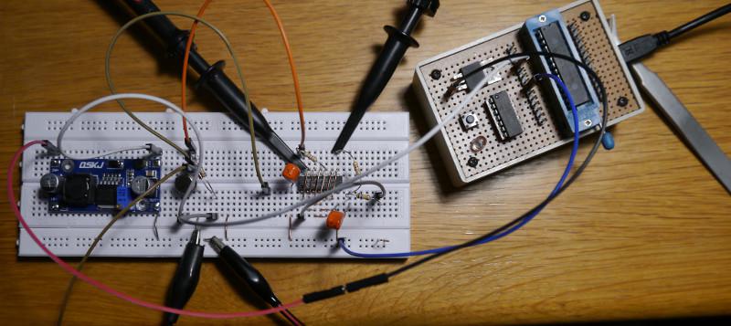 next step is building a thermal chamber, and characterizing the drift of the LT1021-5 reference (untrimmed) over the range 5 degrees C to 40 degrees C. cheer, rob :-) Edited 2022-02-23 00:57 by robert.rozee |
||||
| Volhout Guru Joined: 05/03/2018 Location: NetherlandsPosts: 5059 |
Not sure why you use a 47hcu04 with 6 gates parallel. If you look in the datasheet you will see that the upper mosfet is barely ON with 3.3v drive. A single gate in a 74hct04 has lower impedance ar 3.3v drive when powered from 5v With 5v drive the hcu is superior. Volhout Edited 2022-02-23 02:29 by Volhout PicomiteVGA PETSCII ROBOTS |
||||
| Tinine Guru Joined: 30/03/2016 Location: United KingdomPosts: 1646 |
Did I miss something? Where is the 16bit resolution? |
||||
| robert.rozee Guru Joined: 31/12/2012 Location: New ZealandPosts: 2437 |
i'm following the suggested design put forward in the first post of this thread: https://www.eevblog.com/forum/metrology/an-experimental-pwm-circuit-with-74hcu04/msg3921608/#msg3921608 there have been various discussions over the years about paralleling up CMOS gates to achieve the equivalent of a pair of closely coupled MOSFETs switching between supply rails. the onsemi datasheet for the 74hcu04 confirms: 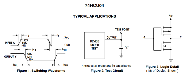 (retrieved from: http://pdf-html.ic37.com/pdf_file_A/20200531/pdf_pdf/pdf4/ONSEMI/74HCU04_datasheet_830450/135209/74HCU04_datasheet.pdf) you are 100% right, i need the full 5 volt drive on the PWM signal going into the 74HCU04. this explains a 0.15v low level output i was seeing when the PWM signal was driven high. will try convering the PWM to 5v levels this evening and see how it looks. still just at the stage of throwing together something with the parts i have to hand. the number of steps (resolution) required depends upon the thermal drift of the reference over the intended operating temperature range. if one assumes worst case this is 5ppm per degree C (for p/n LT1021B-5), over the range 5 to 40 degres C this translates to a maximum of 175ppm. onto this, you need to account for aging of the reference, another 15ppm after 1000 hours. ie, a little under 200ppm, or 0.001v span. if you don't want any external trim resistors (ie, the PWM is able to also correct for the initial inaccuracy of 4.95v to 5.05v) that takes you way out to 10,000ppm. this is where you start needing to make use of a full 16-bits. i'm hoping to be able to trim with a pot, then substitute 2 fixed trim resistors to get within 1000ppm and do the rest with PWM (or a DAC). lets say 12-bits (4000 steps) to be on the safe side, which translates to a MMbasic PWM frequency of either: 1. less than 150Hz, or, 2. between 1250Hz and 10kHz. at the moment i'm leaning towards 3kHz, which gives 13000 steps to work with. cheers, rob :-) Edited 2022-02-23 11:06 by robert.rozee |
||||
| Mixtel90 Guru Joined: 05/10/2019 Location: United KingdomPosts: 7871 |
Wouldn't using pwm feeding into a 4-bit R-2R ladder work well here? Mick Zilog Inside! nascom.info for Nascom & Gemini Preliminary MMBasic docs & my PCB designs |
||||
| robert.rozee Guru Joined: 31/12/2012 Location: New ZealandPosts: 2437 |
have added a BC547 to drive the input to the 74HCU04, with a 4k7 collector resistor to Vref and a 1k5 base resistor. this has improved the output swing of the 74HCU04 considerably. also added a few strategic filter caps to reduce noise. have also dropped the boost converter output down to 8v (from 15v, which was originally required for the AD587). next is to add an opamp to buffer Vref prior to it being supplied to the 74HCU04. this should further reduce noise and in general tighten things up further. the experiment is proving quite interesting  Geoff: the ability to specify precise PWM counts (as negatives) really is quite invaluable, and makes PWM outputs far more versatile. adding a description of this into the manual shouldn't be too complicated, as long as you explain that the negative limit at any given PWM frequency is: cpu_clock \ (64 * frequency) for frequencies of 1249Hz or less, cpu_clock \ frequency for frequencies of 1250Hz or higher, and that this limit corresponds to a positive value of 100%. while exceeding the (negative) limit for any given frequency produces odd results (i've not investigated this much), it doesn't seem to do anything dire. MMbasic carries on running fine. i'm not quite sure i understand how this would work, can you perhaps post a diagram? cheers, rob :-) Edited 2022-02-23 22:23 by robert.rozee |
||||
| Mixtel90 Guru Joined: 05/10/2019 Location: United KingdomPosts: 7871 |
Think of a R-2R ladder. Your zero reference is set by the resistor at the low end to ground. Instead of grounding this resistor connect it to the output from a PWM source. Now, if you are using 10-bit PWM and a 4-bit R-2R you have a 14-bit output, with bits 0-3 on the R-2R and bits 4-14 on the PWM. https://www.edn.com/hybrid-pwm-r2r-dac-improves-on-both/ I believe there are some hybrid DAC chips that use this approach. You can also do it the other way, feeding the PWM in where the LSB input bit would normally be then use a longer R-2R ladder after it. That way you use the R-2R as coarse adjustment and the PWM for fine. https://www.eevblog.com/forum/beginners/r-2r-ladder-and-pwm/ Mick Zilog Inside! nascom.info for Nascom & Gemini Preliminary MMBasic docs & my PCB designs |
||||
| Geoffg Guru Joined: 06/06/2011 Location: AustraliaPosts: 3285 |
That does sound simple, but then explaining the application of such a feature would take a lot more. I understand that is important to you but I am concerned that only you will think that way. But, "never say never". If I sense any demand I will happily make that "feature" part of the mainstream. Geoff Edit: BTW, it is: cpu_clock \ (64 * frequency) for frequencies less than 1249Hz Edited 2022-02-23 23:13 by Geoffg Geoff Graham - http://geoffg.net |
||||
| robert.rozee Guru Joined: 31/12/2012 Location: New ZealandPosts: 2437 |
aha, that suddenly makes sense and extremely handy if you are running short on PWM bits. the one downside i can see (in the present application) is that each of the bits feeding into the R-2R ladder would need to be level-shifted/buffered, which would add further circuitry.also, while for most PWM applications the only thing that matters is that successive codes produce an increasing output, ie, no overlaps. for trimming a voltage reference it is also essential that for a given code (and ambient temperature) the output is always going to be exactly the same (trim) voltage. extra complexity makes this harder to ensure. for the moment, i'm going to run with a 3kHz PWM (giving 13,000 steps) and see how far i can get with that. ultimately, the best solution may well be a 16-bit DAC as Volhout suggested, in which case the micromite will end up serving as just a fancy lookup table! cheers, rob :-) Edited 2022-02-23 23:35 by robert.rozee |
||||
| Geoffg Guru Joined: 06/06/2011 Location: AustraliaPosts: 3285 |
Sorry, I did not read your post correctly. Your original text was correct. Geoff Geoff Graham - http://geoffg.net |
||||
| Volhout Guru Joined: 05/03/2018 Location: NetherlandsPosts: 5059 |
@Robert, I am not sure if I can explain it in words. But there is one thing I have to warn you about. The output of a PWM is dividing the input voltage by a factor DC (Duty Cycle). This means that for a accurate output voltage, you need a accurate input voltage AND an accurate duty cycle. The accuracy of the duty cycle is determined by the resolution of the PWM, but also the delays in the switch (74HCU04) and the level shifter. The transistor level shifter (BC547 and 2 resistors) is relatively slow and highly a-symmetrical in delay (the output high-low is MUCH faster that low-high). Good for an experiment, but not suited for the final product. To give you an idea of the speeds involved: The PWM clock is 40MHz, so 1 lsb equals 25ns. To meet the 1 lsb resolution over the whole range, you need a switch that is faster than 25ns (The HCU is, but the BC547 not). So you will have to replace the BC547 with something that is fast, and translates 3.3V to the levels you require (5V or 6V or 7V). Preferably the slew rate is symmetrical (rise time = fall time). In example a 74ACT04 gate, or alternatively a 74LVC04 gate. And use a single gate input to connect to the MX170 output, otherwise you may load the MX170 output too much and it may become a-symmetrical also. As much ridiculus as it may look, I would build a chain. MX170 -- 1xACT04 buffer -- 5xACT buffer -- 6x HCU switch -- RC filter Get the first ACT buffer as close to the MX as you can, and add a series resistor (value to be tuned, but start with 22 ohm) between the ACT04 and the HCU04. This is to prevent overshoots at the HCU gate inputs that may cause misbehaviour. Put a solid ground plane under the MX-ACT-HCU section and good decoupling at the Vdd pins (for the ACT04 preferably with a ferrite bead to remove switching spikes from 5V. The ACT's are famous for this. Happy experimenting.... Volhout P.S. There is another way of doing this, but it involves analog amplification. power the MX170 from an accurate 3.3V, and use the MX170 output pin to directly drive an amplifying integrator (opamp circuit) that makes 10V swing. You do need a good opamp, but since it controls only few 100 ppm, it does not need to be of the top of the range, but needs to be FET input and low offset drift. Rail-rail is nice, but not essential, especially when you power it from 15V (for the AD587). Simpler, but analog design. P.P.S. The ladder solution can also work but depends on your MX170 algorythm. If you want the most significant 4 bits to be resistor network, then the resistors must be 12bit accurately matched, or better. 0.025% (matched) resistors may be difficult, and driving them with 0.025% matched impedance drivers might also be a challenge. You are asking something more accurate than the ladder networks on the CMM2 that generate video. Not for the faint hearted. Edited 2022-02-24 07:54 by Volhout PicomiteVGA PETSCII ROBOTS |
||||
| KD5ZXG Regular Member Joined: 21/01/2022 Location: United StatesPosts: 53 |
TMUX1134 4x 2ohm SPDT 22nS 74CBT are even quicker, though I find none offering individual control. Not a deal breaker if your intent was parallel. 74CBT3257 4x 5ohm SPDT 6nS Why are no "buffer" or "inverter" gates offered with low resistance, but transmission gate multiplexers exist aplenty??? I have a bunch of 74CBT3253 2x 4way leftover from SSrelay ALU experiments. Specifically, Manchester magnitude comparator, a very fast non-ripple borrow. Check my Hackaday, not going any further off-topic here... Now thinking these parts fast enough for picomite VGA. Low enough resistance to achieve an impedance match. No emitter drop or saturation voltage to worry about. Could be cheap overkill for what you are attempting as well. Edited 2022-02-24 11:15 by KD5ZXG |
||||
| robert.rozee Guru Joined: 31/12/2012 Location: New ZealandPosts: 2437 |
good point, i had been hoping that the BC547 + 4k7 would be 'just good enough' for the job  this evening i tested a slightly simpler approach, reconfiguring the 74HCU04 as a single gate at the input end, that then driving into the remaining five. the BC547 et al are now eliminated, and the output at the 5x paralleled outputs looks like this: this evening i tested a slightly simpler approach, reconfiguring the 74HCU04 as a single gate at the input end, that then driving into the remaining five. the BC547 et al are now eliminated, and the output at the 5x paralleled outputs looks like this: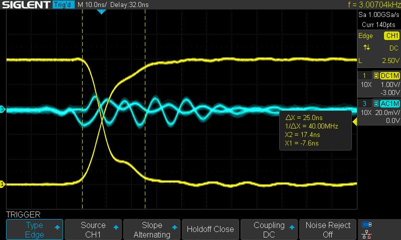 the cursors (dotted vertical lines) are set 25ns apart, or the equivalent of one 40MHz CPU clock cycle of the micromite. as can be seen (yellow trace), both the high-low and low-high transitions now complete within this time interval, and are fairly closely matched in slope. the result is better than i expected! the blue trace (AC coupled) shows ripple of 30mv or so on the reference output at each transition. note that both scope channels are set to 20MHz bandwidth limiting. my shoddy solderless breadboard assembly with long jumper wires is an RF nightmare. neat parts, but too difficult to obtain at the moment. i do have some ADG419 on the way from china, and also see a Vishay DG419 in DIP package can be brought from digikey (https://www.digikey.co.nz/en/products/detail/vishay-siliconix/DG419DJ-E3/2621758) but need to order $70 worth to avoid high shipping costs. it turns out that digikey has nothing else that i want/need in stock - their shelves are quite bare. i remember back in the olden days when you could just wander down the road to the local suppliers to pick up electronic parts... cheers, rob :-) Edited 2022-02-24 21:46 by robert.rozee |
||||
| Glen0 Regular Member Joined: 12/10/2014 Location: New ZealandPosts: 95 |
Haven't had a thorough read of this but it looks like you are looking for a fast switch. Have you considered a TC4427 Fet driver for instance. Relatively cheap and plenty of speed and power. Wide supply and output range. Edited 2022-02-25 08:40 by Glen0 |
||||
| robert.rozee Guru Joined: 31/12/2012 Location: New ZealandPosts: 2437 |
BRILLIANT!!! have just ordered 5x samples of TC4427A from microchip direct, thy should be here in a couple of weeks from a perusal of the datasheet it looks like this device should do exactly what is required, with the A variant having a tighter match of rise and fall propagation delays.cheers, rob :-) Edited 2022-02-25 11:37 by robert.rozee |
||||
| KD5ZXG Regular Member Joined: 21/01/2022 Location: United StatesPosts: 53 |
No shortage of the single pole variety at the moment: SN74LVC1G3157 TI is like six miles away, I've never has to wait more than a day. Not saying how it works from anywhere else. They also have an awesome lunchroom. Its a long story... Edited 2022-02-25 14:54 by KD5ZXG |
||||
| robert.rozee Guru Joined: 31/12/2012 Location: New ZealandPosts: 2437 |
shipping to this part of the world is generally via FEDEX or similar, with shipping costs in the region of $30 being common. not a problem if you're ordering hundreds, or if there are a large number of different parts on your shopping list, but no good if you just need a few of one part. cheers, rob :-) Edited 2022-02-25 14:59 by robert.rozee |
||||
| KD5ZXG Regular Member Joined: 21/01/2022 Location: United StatesPosts: 53 |
Oh, you just need the kind made in New Zealand... |
||||
| robert.rozee Guru Joined: 31/12/2012 Location: New ZealandPosts: 2437 |
alas, all our factories that made such things shut down decades ago :-( |
||||
| The Back Shed's forum code is written, and hosted, in Australia. | © JAQ Software 2025 |
