
|
|
Forum Index : Microcontroller and PC projects : RaspberryMite
| Author | Message | ||||
| Mixtel90 Guru Joined: 05/10/2019 Location: United KingdomPosts: 8911 |
Is it worth me continuing with this idea? Overall size, fixing holes, GPIO position, general I/O are all in the same positions as a RPi 3B. That doesn't necessarily mean it will fit the same cases though! The heights of components will come into it. I can't get the SD card on the end unless it's a SMD one on the bottom of the board like a RPi. 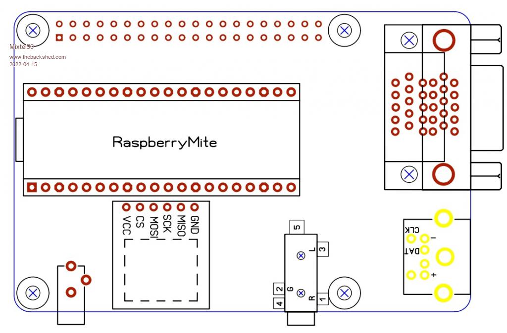 Edited 2022-04-15 19:10 by Mixtel90 Mick Zilog Inside! nascom.info for Nascom & Gemini Preliminary MMBasic docs & my PCB designs |
||||
| Amnesie Guru Joined: 30/06/2020 Location: GermanyPosts: 757 |
Inspired by a comment I first thought it would be a good idea because there are a lot of cool (even CNC milled) cases for the Pi, but then I realized that you can't manage the VGA connector to any of the outlines of the RaspberryPi components. I think it only would be a real benefit, if we could use RaspberryPi cases... Otherwise I don't see any good reason for it. But maybe there is something I have not thought about :) Edit: Maybe one could modify a RaspberryPi case in such a way the VGA connector fits... And doesn't look ugly in the end... �  Another downside (at least for my why I hate the normal cases) the RaspberryPi is a mess! All cables to all sides..  Edited 2022-04-15 19:55 by Amnesie |
||||
| Mixtel90 Guru Joined: 05/10/2019 Location: United KingdomPosts: 8911 |
I think the VGA connector is lower than the Pi USB connectors so there may be a dividing piece to be cut out of the case there. There would be a slight gap above it, I think. The PS/2 connector is roughly the same height so you might get away with that (I've not measured anything). I have a feeling the PS/2 is slightly wider. I could move the power and audio jacks to the end, but it would be very non-standard for a Pi. The power jack would need filing out. Mick Zilog Inside! nascom.info for Nascom & Gemini Preliminary MMBasic docs & my PCB designs |
||||
| Rickard5 Guru Joined: 31/03/2022 Location: United StatesPosts: 463 |
MICK That is a Killer GOOD IDEA I SO LOVE THAT for embedded projects, but if you were to listen to my Humble wish I'd Love to see the VGA and Kb circuits be separate Modules that can be attached with board headers or single row ribbon cables for a few reasons, 1. to make the microcontroller fit in more places, like board here and VGA where it fits on a project ect... 2. save $$$ for projects like robotics or motion control, Animatronics, you only nerd the KB and VGA when programming so several projects can share the same VGA and KB Modules I may be Vulgar, but , while I'm poor, I'm Industrious, Honest, and trustworthy! I Know my Place |
||||
| matherp Guru Joined: 11/12/2012 Location: United KingdomPosts: 11512 |
Mick I made Pi-HAT compatible boards for the MM2, MM+, and MMX that did fit the Pi cases and they never got any traction so you may find initial interest but no follow up https://www.thebackshed.com/forum/ViewTopic.php?TID=10043 |
||||
| Mixtel90 Guru Joined: 05/10/2019 Location: United KingdomPosts: 8911 |
Unfortunately you can have a VGA version OR a Normal version - you can't attach a VGA display to a Normal PicoMite. If you use the pins allocated to VGA for something else then you can't run the VGA firmware. You can program any PicoMite via the USB console, of course. Just use a Normal PicoMite and accept that you can't have a VGA display on it at all. I could easily take the keyboard and VGA off the above design but there'snot a lot of point to the design if I do. The PicoMite is already a general purpose design. For maximum flexibility just mount one on some stripboard or something, with some connectors or terminals. Program it over the USB. ------------ @matherp Yep, I know. TBH I'm not sure this is worth bothering with. Mick Zilog Inside! nascom.info for Nascom & Gemini Preliminary MMBasic docs & my PCB designs |
||||
| lizby Guru Joined: 17/05/2016 Location: United StatesPosts: 3784 |
It's much larger, and not VGA, and not case-fitting, and not in Pi footprint, but there already is a Picomite with 2x20 connector PCB here ~ Edited 2022-04-15 21:57 by lizby PicoMite, Armmite F4, SensorKits, MMBasic Hardware, Games, etc. on FOTS |
||||
| al18 Senior Member Joined: 06/07/2019 Location: United StatesPosts: 238 |
Mick, I like the design - don�t change a thing. Your design would fit into on the stackable Pi cases such as this one https://www.amazon.com/Layers-Clear-Stackable-Raspberry-Heatsink/dp/B07BGYGLZG Once you get your Game PicoMite board finalized, you could also make a gaming hat with the two DB9 connectors and a spot for the 5 pin Analog Joystick Edited 2022-04-15 22:56 by al18 |
||||
| Volhout Guru Joined: 05/03/2018 Location: NetherlandsPosts: 5931 |
Hi Mick, Something to think about. The Rpi(0/2/3/4) has 26 GPIO lines connected to the 40pin connector. The picomite with VGA and SD card and PS2 keyboard does not have 26 free IO pins. This means that you should not do this project if you plan to support Rpi HAT's. Only some will work, many will not since you simply doe not support all the IO pins. In essence you will have to develop your own HAT's based on the available number of IO's that you have. So you will have to develop your own HAT's. IF your plan is to support Rpi cases, with little grinding you could use the Rpi cases (as others suggested). In that case I would definitely put the micro-sd card reader on the bottom, same as Rpi has. Since that is one thing we could make fit. But honestly, you could make your own "standard" by turning the game VGA version (that you have a good and cheap case for) into a modular system. Adapt the game VGA design to support "HAT"'s and develop one or two yourself. - a mechanical relays (4) and optocoupler input board (4) - a stepper motor board - a esp8266 wifi support board - a "play to toy" board based on some common I2C devices PicomiteVGA PETSCII ROBOTS |
||||
| Mixtel90 Guru Joined: 05/10/2019 Location: United KingdomPosts: 8911 |
If I wanted something like that I'm not sure I'd do it that way. I could already mount the miniVGA like that, but why so many VGA and PS/2 ports? I would probably forget them and have a stack of very simple PicoMite to pins boards (possibly my PicoMIte Backpack with bits missing? https://www.thebackshed.com/forum/ViewTopic.php?TID=13981&P=4#173883 ) all linked via SPI or I2C. Defining one as the master would then let you use the other four for parallel processing, expanded I/O or whatever. You could perhaps put PS/2 and VGA on just one of them (may or may not be the bus master). I've looked at the design again and there's not enough I/O spare on the PicoMite to necessitate a 2x20 connector. It couldn't really be compatible in any way with the CMM2 or the RPi. The only thing I can see in favour of this now is that it might, in a few cases, be less scary for those who are familiar with the SBC way of doing things. ------------------ @Volhout I'm already doing something like that. The miniVGA has a 2x13 I/O port. My idea is to plug "things" into that. The port has virtually the same signals as the range of Micromite-based I/O modules so you would be able to plug those same "things" into RS485, I2C or whatever via the I/O modules or use them independently via the miniVGA. The first of the "things" is designed (4x opto in, 3x relay, 3x analogue in), but I really need to look at one or two more ideas. I like the idea of a stepper motor board. :) Edited 2022-04-16 01:54 by Mixtel90 Mick Zilog Inside! nascom.info for Nascom & Gemini Preliminary MMBasic docs & my PCB designs |
||||
| MikeO Senior Member Joined: 11/09/2011 Location: AustraliaPosts: 275 |
Mick, Nice I like this, I think combining MMBasic hardware with other CPUs that have network ability can have a lot possibilities. I did a post some time ago using a MX170/raspberry Pi combination here however the project has more recently been expanded to use the Picomite , all I have done so far is on my site, actually the first project "mmPi" has been accepted for publication in Silicon Chip , Circuit Notebook section next "available" slot, bit more promotion for the Micromite hopefully! Codenquilts |
||||
| The Back Shed's forum code is written, and hosted, in Australia. | © JAQ Software 2026 |
