
|
|
Forum Index : Microcontroller and PC projects : PWM to +/- 10V
| Author | Message | ||||
| Volhout Guru Joined: 05/03/2018 Location: NetherlandsPosts: 5058 |
Hi Tinine, For a 10kHz PWM you could try the opamp circuit at below: It converts 3.3V PWM to +/- 10Vdc The opamp (TL072) is not critical. It combines gain with active filtering. The active filter for rejecting the 10kHz to below 1mVrms. 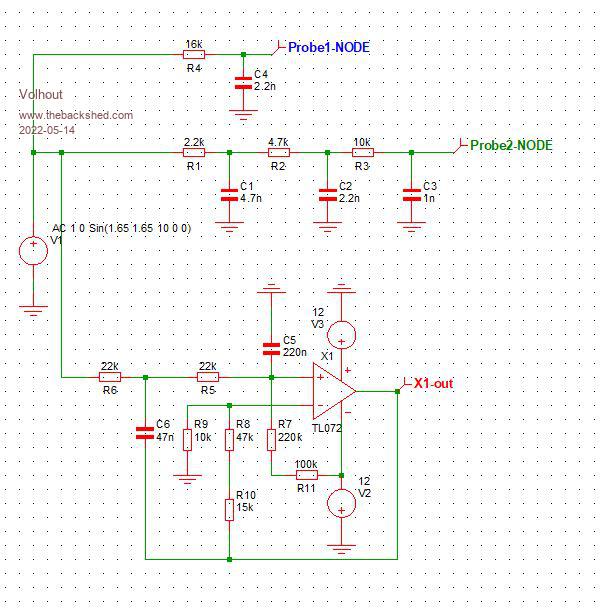 I added the other (100kHz filters) in the graph below. These are not suitible. 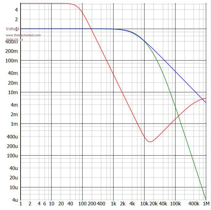 The conversion from 3.3V to +/-10V can be seen here. 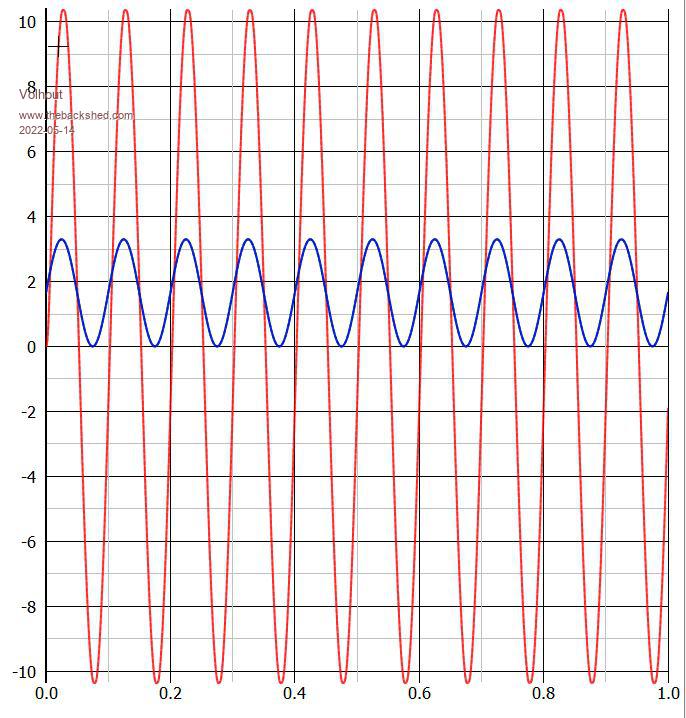 I used E12 resistors (so 62k is 47k+15k, 320k=220k+100k) to use easily available components. Edited 2022-05-14 00:40 by Volhout PicomiteVGA PETSCII ROBOTS |
||||
| Tinine Guru Joined: 30/03/2016 Location: United KingdomPosts: 1646 |
@Volhout: Many, many thanks for this...this is HUGELY appreciated! �  Whilst my crude DAC does work, it just doesn't feel refined enough. I will run both versions to compare �  Not sure if I have the required component values but I will order them if not. Would you believe it, I read your post just after I walked-out of CPC-Farnell in Preston and it was closing time �  Unrelated side-story: The first thing that hit me was the TL072 because I have been upsetting some people elsewhere. � Purist guitarists are a very strange bunch and will believe any old garbage. This is a distortion pedal, the "Klon Centaur" (I call in Clown Central. ) 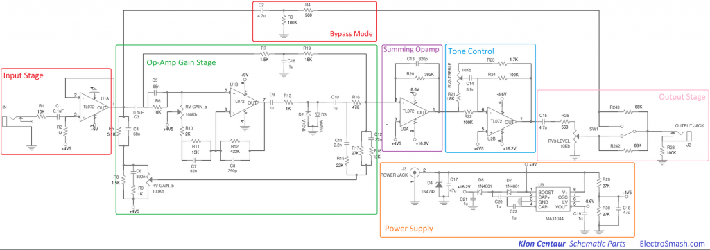 The designer published the schematic and one can buy a ready-made clone for < $50 BUT the purists insist that the originals "sound better" � However...they refuse to participate in a blind test � eBay: Now you're gonna want $5K every time I use your DAC � Craig Edited 2022-05-14 16:03 by Tinine |
||||
| Mixtel90 Guru Joined: 05/10/2019 Location: United KingdomPosts: 7865 |
Want a PCB with 5 blue LEDs on it to make it sound better than the original? I can do a retrofit module to improve any of the other modules (it's a small box and you attach it using 2 wires) for a mere 2000UKP. One of the LEDs is an indicator to show that the device is functioning. The others are inside the box, introducing a carefully measured amount of distortion and noise onto the supply rail of the effects box using a system of rambodynamic resistification limiting. Note that the 4 LEDs must be in darkness (the board won't work in the open) and the LEDs are mechanically arranged to produce a combined light pattern so the board layout is critical. Edited 2022-05-14 16:35 by Mixtel90 Mick Zilog Inside! nascom.info for Nascom & Gemini Preliminary MMBasic docs & my PCB designs |
||||
| PeterB Guru Joined: 05/02/2015 Location: AustraliaPosts: 655 |
Craig. Does the distortion thing use low copper wire? That makes all the difference. Have you tried my 2 resistors? If not why not?  Peter Please add O2 P Edited 2022-05-14 16:37 by PeterB |
||||
| Tinine Guru Joined: 30/03/2016 Location: United KingdomPosts: 1646 |
@Mixtel90/PeterB I suspect that you guys have been having a good laugh on the audiophile forums How about the $2K+, 1-metre-long power (kettle) cords? Never mind the cr@ppy 2.5mm T&E behind the walls because that's invisible, I have it on good authority that a "de-oxygenated" kettle cord will vastly improve the audio "spatial definition"....I also have a bridge for sale. Craig @PeterB Today is/was my breadboarding day but the electric fork-truck just died and I have been roped into working on it...grrr |
||||
| phil99 Guru Joined: 11/02/2018 Location: AustraliaPosts: 2610 |
The expression "Beauty is in the eye of the beholder" can be generalized as:- Art is in the mind of the beholder. It has no objective existence so what sounds good or looks good is up to our imaginations. At the end of the day we are all just dumb animals, clever yet stupid. . Edit Went right off topic there. See line above:) Edited 2022-05-14 18:05 by phil99 |
||||
| Tinine Guru Joined: 30/03/2016 Location: United KingdomPosts: 1646 |
Art-dealing is in the mind of the money-launderer � WRT: the chicks in this town, beauty is in the eye of the beer-holder Edited 2022-05-14 18:51 by Tinine |
||||
| Volhout Guru Joined: 05/03/2018 Location: NetherlandsPosts: 5058 |
Everything the audiophiles say is true. The human ear is the most adaptive human sensor. You can willingly and also unwillingly tune it. As proof: listen 1 hour to MW radio from a tube radio with paper cone loudspeaker. After 1 hour it sounds good. Audiophiles are so easy to fool..... PicomiteVGA PETSCII ROBOTS |
||||
| Tinine Guru Joined: 30/03/2016 Location: United KingdomPosts: 1646 |
And a fool and his money are easily parted. Managed to escape and just got to CPC Farnell before closing. Man, even resistors are out stock. Purchased a variety pack of 610 so I hopefully have all I need to drive both DACs |
||||
| Turbo46 Guru Joined: 24/12/2017 Location: AustraliaPosts: 1639 |
The circuit I proposed earlier will give +/- 10 volts centred around 1.65 volts. If an extra -ve input is applied to the inverting input to the op amp - turning it into a summing circuit you could apply an offset to it to make the output of the op amp zero at mid point (50% PWM). I would use a resistor and LED in the -12 volts to earth to provide a -ve reference and an appropriate value of resistor from there to the inverting input to provide an offset to make the 50% PWM give an output of zero volts with symmetrical outputs for 0% and 100%. I don't believe the original circuit does this. A trimmer pot in that circuit could be used to give a zero null on the output. A simpler way would be to AC couple the input to the circuit and connect the non inverting input to ground via an appropriate resistor. In the advent of a failure of the PWM signal or the micro the output of the op amp would be zero if that is a good thing. Two or three stage filters in either circuit would help. Bill Keep safe. Live long and prosper. |
||||
| Tinine Guru Joined: 30/03/2016 Location: United KingdomPosts: 1646 |
Got sidetracked yesterday so only got to play with this stuff today. Volhout's circuit appears to be working well on the breadboard: 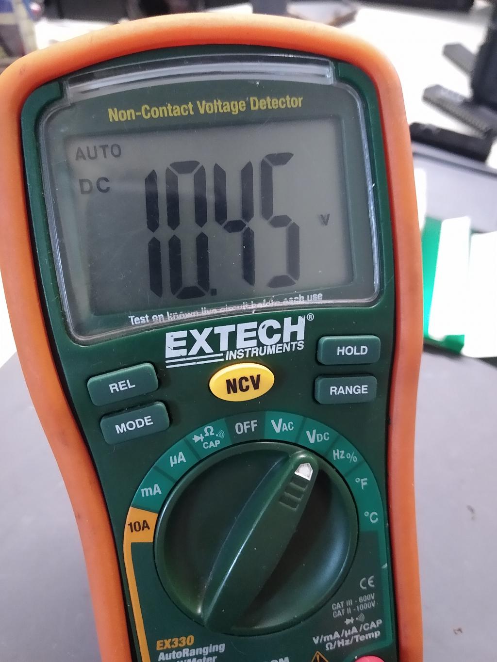 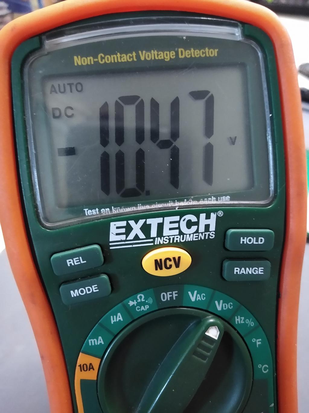 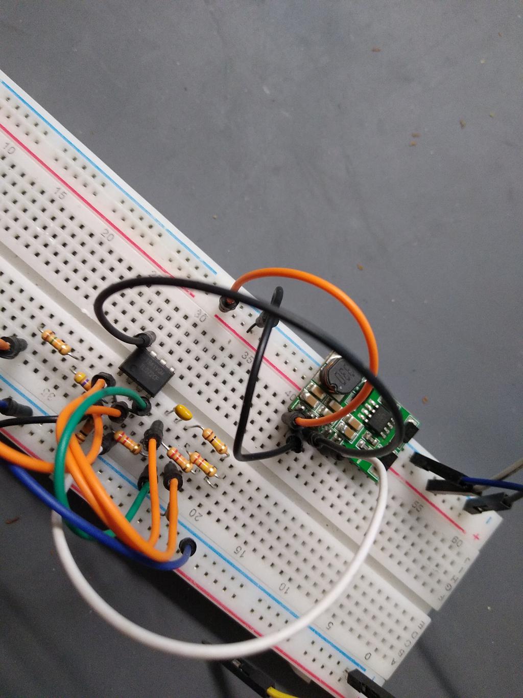 14 bits give me a resolution of 0.0012V and I'm getting those increments � Slight (expected) null-offset, the zero-point is 8059 as opposed to 8192 � 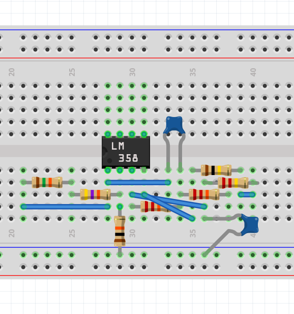 Craig Edited 2022-05-17 00:44 by Tinine |
||||
| Tinine Guru Joined: 30/03/2016 Location: United KingdomPosts: 1646 |
A very good point....it would be a very bad thing if the axis ran away. However, I run very tight error-traps. The PID runs at 1KHZ and the position of the axis must be very close to the commanded position. If the actual position gets out of the window, the entire machine shuts down Craig |
||||
| Turbo46 Guru Joined: 24/12/2017 Location: AustraliaPosts: 1639 |
To quote a friend from my working days "Belt and braces". Bill Keep safe. Live long and prosper. |
||||
| Mixtel90 Guru Joined: 05/10/2019 Location: United KingdomPosts: 7865 |
If the cost of a capacitor makes it failsafe then why not put one in? Mick Zilog Inside! nascom.info for Nascom & Gemini Preliminary MMBasic docs & my PCB designs |
||||
| Tinine Guru Joined: 30/03/2016 Location: United KingdomPosts: 1646 |
Because that would still be reliant on a semiconductor, outputting zero-volts. There are many possible causes of axis runaway, the main one being a fractured encoder-cable-conductor in a cable chain. Furthermore, this is full torque-mode PID meaning 0V only means zero-current to the axis motor. A 200Kg linear axis, hurtling along at 1000mm/sec will keep coasting and could cause damage/injury. I have watchdogs on top of watchdogs (not the MMBasic WD) that will shut down the power source and engage dynamic braking (loss of power shorts the motor windings). |
||||
| Turbo46 Guru Joined: 24/12/2017 Location: AustraliaPosts: 1639 |
Sounds like you have already discarded the suggestion but I'll show it anyway. 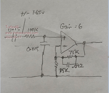 This circuit has a low pass 3 db point at 100Hz with a gain of 6. It is non inverting unlike the original and will give a symmetrical output. This gives a higher input impedance which allows for higher value resistors and therefore smaller capacitors. The AC input coupling will mean that the output will drop to zero if the input fails. The gain could be nudged up by adding a high value resistor in parallel with the 15k or down with a small value resistor in series with the 75k. No filing. FWIW Bill Edited 2022-05-17 16:05 by Turbo46 Keep safe. Live long and prosper. |
||||
| Tinine Guru Joined: 30/03/2016 Location: United KingdomPosts: 1646 |
Getting these spikes directly from the buck-booster (5v to +/-12v). Is this "tolerable" or do I need more filtering? I don't intend to actually use this booster beacuse I use an ATX Pico power supply but I suspect that I might see something similar. Craig 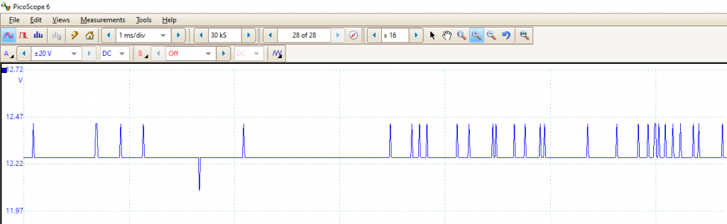 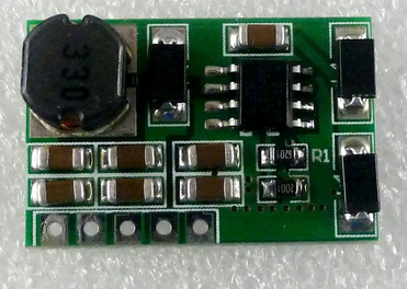 |
||||
| Tinine Guru Joined: 30/03/2016 Location: United KingdomPosts: 1646 |
Hey Bill I'm always interested. Would you please re-post the sketch without the watermark? Cheers! Craig |
||||
| Turbo46 Guru Joined: 24/12/2017 Location: AustraliaPosts: 1639 |
Done. 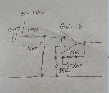 Bill Keep safe. Live long and prosper. |
||||
| PeterB Guru Joined: 05/02/2015 Location: AustraliaPosts: 655 |
Bill. I think that Craig's circuit is part of a servo and would need a response down to d.c. I may be wrong. He hasn't tested my circuit yet after all the hours I spent wearing my slide rule down to the bone. These young blokes have no respect for we old people. PeterB  |
||||
| The Back Shed's forum code is written, and hosted, in Australia. | © JAQ Software 2025 |
