
|
|
Forum Index : Microcontroller and PC projects : Can anyone convert this to MMBasic?
| Page 1 of 2 |
|||||
| Author | Message | ||||
lew247 Guru Joined: 23/12/2015 Location: United KingdomPosts: 1709 |
Can anyone convert this to MMBasic? It's the code for a Tetra detector, as in the radio's used by Police, Ambulance and Fire services in Europe The original code was written for a PIC16F818 and uses code like this which I have no clue about ; FI1216 control, ADC and LED bar driver ; V0.0 141130 Initial draft ; V0.1 141201 Done ADC, LED bar ; V0.2 141202 Subroutines, TMR0 ; V0.3 141203 Tetra 4s, MAX HOLD function ; V0.4 141204 Fixed AD, lose controls, enter buttons ; V0.5 141206 I2C ; V0.6 141207 Fixed I2C ; V0.7 141228 BRT Button ; V0.8 141231 THR Button ; V0.9 150118 Cal levels FI1216, f(LO) ; V0.10 150119 THR setting ; V0.11 150119 EEPROM R/W ; V1.0 150119 Release LIST P = 16F818 , F = INHX8M #include < p16f818.inc > __CONFIG _WDT_OFF & _PWRTE_OFF & _INTRC_IO & _MCLR_ON & _BODEN_OFF & _LVP_OFF & _CPD_OFF & _WRT_ENABLE_OFF & _DEBUG_OFF & _CCP1_RB2 & _CP_OFF ; Equates RESET_V EQU 0x00 ; Address of RESET Vector OSC_FREQ EQU D'8000000' ; Internal Oscillator Frequency is 8 MHz ; Registers FLAGS EQU 0x20 ; Various flags THRLVL EQU 0x21 ; Threshold level set via UI MAXH EQU 0x22 ; LEVEL MAX HOLD value to be shown on LED bar TEMPBAR EQU 0x23 ; Pattern on LED bar if it's blanked (BRT) TEMPTHR EQU 0x24 ; Used in threshold set routine BRITE EQU 0x25 ; LED Brightness T4S EQU 0x26 ; Tetra 4s timing I2CDELAY EQU 0x27 ; Used for I2C timing I2CBUF EQU 0x28 ; Used for I2C data I2CCNT EQU 0x29 ; Used for I2C bitbanger DB2 EQU 0x30 ; Stealth byte for prescaler (0x50-0x5F) TEMPW EQU 0x40 ; Context saving for interrupts TEMPSTATUS EQU 0x41 ; in all banks ; Defines #define LEDS PORTB ; 8 LED bar RB0-3 GRN, RB4,5 ORG RB6,7 RED #define RSSI PORTA , I do have a copy of the full code if anyone can convert into Basic or write a simple program to tune the tv tuner, monitor the output and display by led or audible tones depending on the signal strength In the UK the mobiles transmit on 199 25Khz channels in the frequency range 380.0125Mhz - 384.9875Mhz They send a sync signal to the base stations every 4 seconds so the "beacon" can be picked up and displayed by a tone, light or other means There are many ways to do this including using an SDR radio and rtl_power or similar app There are commercial units that do the same thing such as Target Blu Eye and Python Detectors All they do is monitor for the data burst and display that it's been received, there is no decoding or monitoring of the tetra signal at all The version I'm thinking of building uses an old analogue tv tuner as the bandwidth of 1 channel is 8 Mhz which is enough to monitor the whole tetra band at once looking for any signals All the tv tuner has to do is be tuned to around 382.50Mhz which most wideband tuners could do as they covered the VHF and Cable channels as well as the UHF ones One such tuner was the FI1216 which is tuned by it's I2c bus.Remove the TDA9800 demodulator and insert an AD8307 92 dB Logarithmic Amplifier and then send the output into a pic as the person who wrote the code did but I reckon a Pi Pico running MMBasic would do it a lot better and easier IF anyone could program it You can read about the project on the authors page HERE but he gave up on it due to patent trolls threatening him so he removed the code from online This will only work properly if a proper tuned antenna for that frequency is attached as the signals will be pretty weak 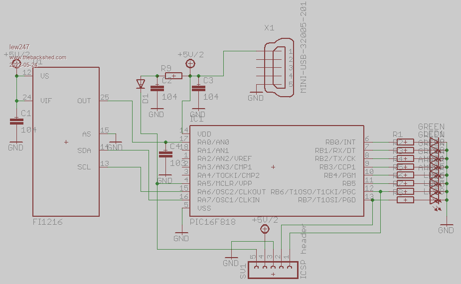 You can see a video of a similar type device working on YouTube here |
||||
| thwill Guru Joined: 16/09/2019 Location: United KingdomPosts: 4369 |
Not me I'm afraid. I'm guessing that is PIC assembler, the ';' characters start code comments. However it seems to have lost lots of newline characters ... and possibly gained some too ... that's why it looks so completely incomprehensible. Best wishes, Tom Edited 2022-05-24 05:16 by thwill MMBasic for Linux, Game*Mite, CMM2 Welcome Tape, Creaky old text adventures |
||||
| thwill Guru Joined: 16/09/2019 Location: United KingdomPosts: 4369 |
If you want to send me the source then I can probably write an MMBasic program to reformat it so it is at least legible which will make it much easier to determine how doable a conversion project would be. Best wishes, Tom MMBasic for Linux, Game*Mite, CMM2 Welcome Tape, Creaky old text adventures |
||||
| Volhout Guru Joined: 05/03/2018 Location: NetherlandsPosts: 5931 |
I am afraid no-one can. This is only part of a project. It is a header file for a project, that defines the fuses of the particualr PIC processor (like WDT = watchdog timer ON) and a set of definitions for variables used in the C file (or assembly file, or basic file). As Tom pointed out, the ";" is a separator used in MPASM (Microchip Assembler). In essence: you are missing part of this project. This is only one of multiple (2 or more) files. PicomiteVGA PETSCII ROBOTS |
||||
| JohnS Guru Joined: 18/11/2011 Location: United KingdomPosts: 4335 |
Start from scratch. Make sure the hardware helps instead of hinders. John |
||||
TassyJim Guru Joined: 07/08/2011 Location: AustraliaPosts: 6538 |
The datasheet for the TV tuner IC is readily available. Pin 25 is the audio out which the PIC monitors, probably just for any activity. Not a major programming challenge. Jim VK7JH MMedit |
||||
| thwill Guru Joined: 16/09/2019 Location: United KingdomPosts: 4369 |
It looks like an interesting project - except possibly making oneself visible to "patent trolls". Lewis does have the full code, as he said in the original post what he posted was only a snippet (which seems to have been mangled in the process). The actual code, which I've now seen, is properly formatted (so no need for me to write code to reformat it) and is well documented PIC assembler. I imagine it could be converted to MMBasic relatively easily, or used as a reference if someone wanted to start from the datasheet instead. I would help if I could Lewis but I've got too much on my plate already. Best wishes, Tom Edited 2022-05-24 19:31 by thwill MMBasic for Linux, Game*Mite, CMM2 Welcome Tape, Creaky old text adventures |
||||
| lew247 Guru Joined: 23/12/2015 Location: United KingdomPosts: 1709 |
FQ1216ME.pdf I've been trying to work out how to use the I2C bus to program the tuner to go to 382.5Mhz I've attached the datasheet of the tuner I'm going to use which gives details of the I2C bus and how to program it but it's all gobblydygook to me I've got as far as I need to set the Tuner to Mid Band which is 0 1 0 0 0 x x x �P0-P7 the AGC controls need to be set to either 001 high, 010 (power on mode) or 101 low to set the frequency it "seems" to need the following Address Byte �ADB Divider Byte 1 �DB1 Divider Byte 2 �DB2 Control Byte CB Bandswitch Byte BB Auzilary Byte AB (AGC) Using the example given they used 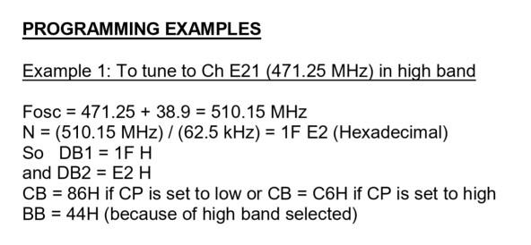 I've managed to work out that I need to set the tuner to 421.5Mhz? or do I considering I'm removing the demodulator from inside it Using this frequency I need to set the following 421.4 MHZ N = 1A 56 DB1 = 1A H DB2 = 56 H CB = ? BB = ? I'm conpletely stumped to be honest If anyone gets the time or inclination to look at the datasheet could you tell me the data I need to send on the I2C bus to do the 2 following things please Set Frequency to 382.5Mhz or very close to it Set AGC level to 001 Set AGC level to 010 Set AGC level to 101 I can work out the rest of the program myself (I think) it's just programming the actual tuner that's my issue because my knowledge of I2c is cr@p and the ability of my brain to process and store the knowledge to understand it went when I got my memory issues Of course I coule be completely wrong in how I've interpreted the datasheet and maybe if I am then let me know and I'll just give up on this Edited 2022-05-24 20:42 by lew247 |
||||
| Volhout Guru Joined: 05/03/2018 Location: NetherlandsPosts: 5931 |
Hi Lew247, Since you are in the UK you will have either a system B/G or system I tuner (not system L for France). Meaning the tuner runs at 38.9MHz IF (intermediate frequency). When you program the divider to &h1A56 to achieve 421.4MHz you use 16 steps per MHz in the PLL settings (62.5kHz step). Since you want to tune to 380MHz, you are to use MID band (not high band since that starts at 442MHz up). Mid band is set with writing &bxxx00002 (or &h02) to BB. The control byte (CB) must be programmed with &b10000110 to work with 62.5kHz steps, and use low current charge pump (slower tuning, but better matching 62.5kHz steps). So CB must be set to &h86. I hope this helps, Volhout Edited 2022-05-25 01:48 by Volhout PicomiteVGA PETSCII ROBOTS |
||||
| lew247 Guru Joined: 23/12/2015 Location: United KingdomPosts: 1709 |
Thanks Volhout, it does, it's more or less what I thought But I still don't understand how to actually send the data to the tuner Do I open I2c then send each command one after the other, or seperatly or altogether like how can I tell it that I want to send the BB command for instance |
||||
| Volhout Guru Joined: 05/03/2018 Location: NetherlandsPosts: 5931 |
@lew247 Depending on the connection you make to pin 6 of the tuner, the I2C address changes. In the datasheet is the 8 bit address, but MMBasic uses 7bit addressing. pin6=GND : I2C address = &h60 pin6=1.7V: I2C address = &h61 pin6=3.3V: I2C address = &h62 pin6=5V : I2C address = &h63 I have not been able to find out what the register addresses are, so it may be possible that this tuner does not support individual register setting. And you must send all 6 registers always. This you should be able to derive from the PIC code. Good luck, nice project..... PicomiteVGA PETSCII ROBOTS |
||||
| Devaz Newbie Joined: 13/07/2022 Location: NetherlandsPosts: 7 |
@lew247 Have u try this Wire.beginTransmission(0x60); Wire.write(0x1A); // DB1 Wire.write(0x56); // DB2 Wire.write(0x02); // CB Wire.write(0xCE); // BB byte msg = Wire.endTransmission(); I'm using the FQ1216ME and its working with this settings. Now i'm testing the FI1216 but it looks that its not the same as the FQ tuner. Grz |
||||
| lew247 Guru Joined: 23/12/2015 Location: United KingdomPosts: 1709 |
Thanks In the end it was an Fi1216 i managed to get and yes the settings are different but hopefully not too much this is the Fi1216 datasheet which contains the commands fi1216.pdf I only need it to turn to mid band and tune to 382.5 or whichever closest frequency to that matches with the step size selected The step size doesn't matter as it will be staying on that one frequency I just got the boards back from JLPCB today so once I get someone to take out the TDA9800T and solder in the board I had made, It should be relatively easy to get working I made two boards, one for the Fi1216 that either an OLED display or one of the 2.5/3.5 displays will fit onto along with a gps/compass unit so the unit can show true speed when mounted in the car as well as tetra alerts the 2nd board contains the replacement for the TDA9800T to convert the signal to voltage to feed to the picromite (the board says FM1216 but should work for either) 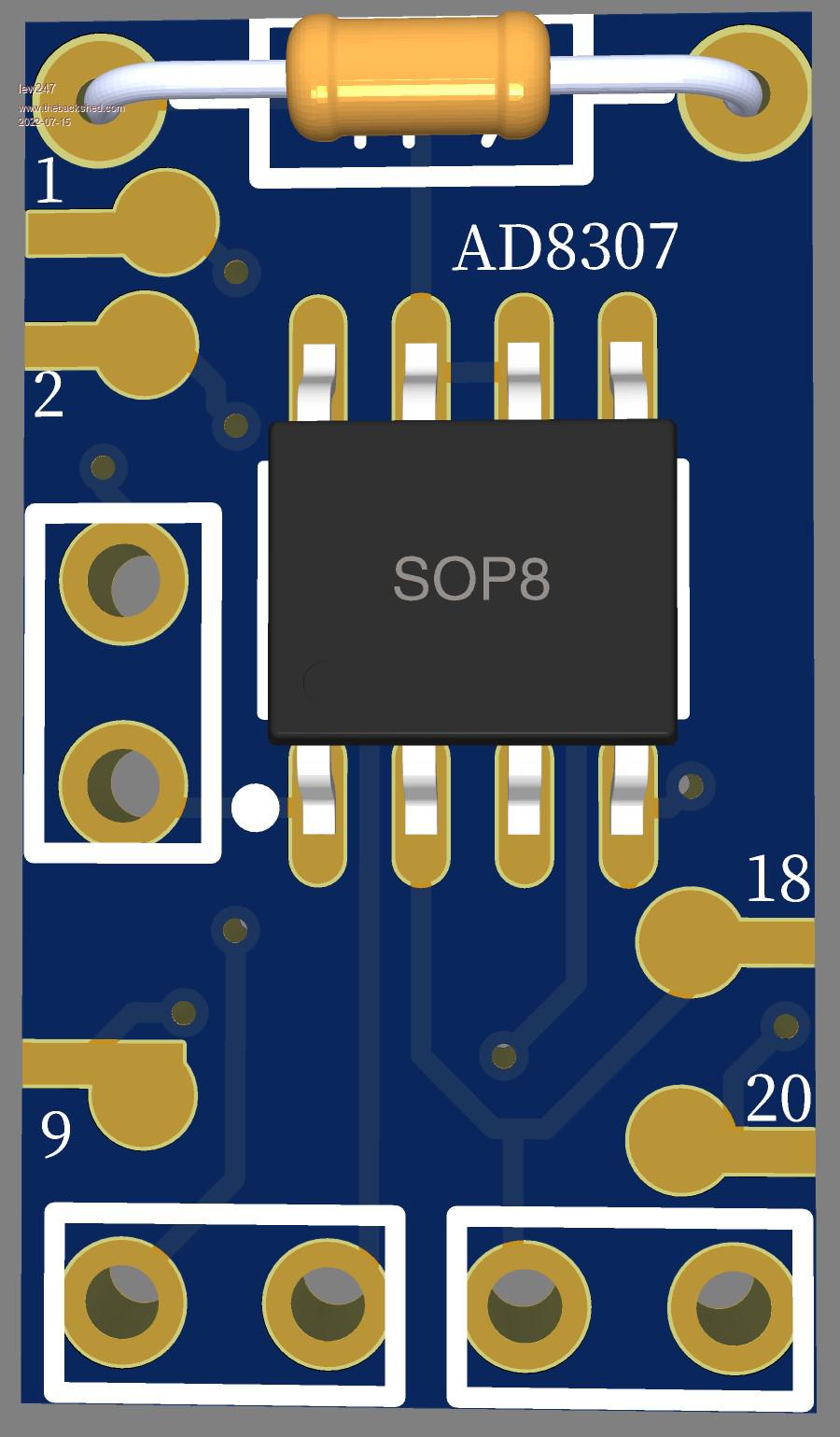 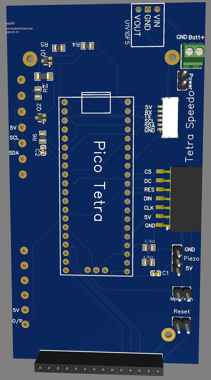 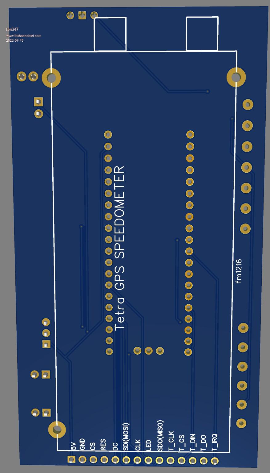 |
||||
| Volhout Guru Joined: 05/03/2018 Location: NetherlandsPosts: 5931 |
I think BB=&h02, CB=&h86 (or &hCE ??). Regards, Volhout PicomiteVGA PETSCII ROBOTS |
||||
| Devaz Newbie Joined: 13/07/2022 Location: NetherlandsPosts: 7 |
@lew247 The PCB is nice but i think u need an extra amplifier for the signal. With commands are u use for the Fi1216 DB1 = DB2 = CB = BB = Grtz Edited 2022-07-16 04:23 by Devaz |
||||
| pwillard Guru Joined: 07/06/2022 Location: United StatesPosts: 341 |
Considering that the source code *should* have looked like this: ; FI1216 control, ADC and LED bar driver ; V0.0 141130 Initial draft ; V0.1 141201 Done ADC, LED bar ; V0.2 141202 Subroutines, TMR0 ; V0.3 141203 Tetra 4s, MAX HOLD function ; V0.4 141204 Fixed AD, lose controls, enter buttons ; V0.5 141206 I2C ; V0.6 141207 Fixed I2C ; V0.7 141228 BRT Button ; V0.8 141231 THR Button ; V0.9 150118 Cal levels FI1216, f(LO) ; V0.10 150119 THR setting ; V0.11 150119 EEPROM R/W ; V1.0 150119 Release LIST P #include <p16f818.inc> __CONFIG _WDT_OFF & _PWRTE_OFF & _INTRC_IO & _MCLR_ON & _BODEN_OFF & _LVP_OFF & _CPD_OFF & _WRT_ENABLE_OFF & _DEBUG_OFF & _CCP1_RB2 & _CP_OFF ; Equates RESET_V EQU 0x00 ; Address of RESET Vector OSC_FREQ EQU D'8000000' ; Internal Oscillator Frequency is 8 MHz ; Registers FLAGS EQU 0x20 ; Various flags THRLVL EQU 0x21 ; Threshold level set via UI MAXH EQU 0x22 ; LEVEL MAX HOLD value to be shown on LED bar TEMPBAR EQU 0x23 ; Pattern on LED bar if it's blanked (BRT) TEMPTHR EQU 0x24 ; Used in threshold set routine BRITE EQU 0x25 ; LED Brightness T4S EQU 0x26 ; Tetra 4s timing I2CDELAY EQU 0x27 ; Used for I2C timing I2CBUF EQU 0x28 ; Used for I2C data I2CCNT EQU 0x29 ; Used for I2C bitbanger DB2 EQU 0x30 ; Stealth byte for prescaler (0x50-0x5F) TEMPW EQU 0x40 ; Context saving for interrupts TEMPSTATUS EQU 0x41 ; in all banks ; Defines #define LEDS PORTB ; 8 LED bar RB0-3 GRN, RB4,5 ORG RB6,7 RED #define RSSI PORTA Means to me that even if you *HAD* all the source... it would be a task to make it usable again. Was it intentionally mangled like that? |
||||
| Devaz Newbie Joined: 13/07/2022 Location: NetherlandsPosts: 7 |
It's easy to write some new code for it. The difficulty is the hardware and the low signal being received. Grtz Edited 2022-07-16 05:11 by Devaz |
||||
| Devaz Newbie Joined: 13/07/2022 Location: NetherlandsPosts: 7 |
Have u test this settings with the FI1216 ? Edited 2022-07-16 05:13 by Devaz |
||||
| Devaz Newbie Joined: 13/07/2022 Location: NetherlandsPosts: 7 |
@lew247 I think you were looking for this file ;-) pdf-tetra-detector.zip Grtz |
||||
| Devaz Newbie Joined: 13/07/2022 Location: NetherlandsPosts: 7 |
@lew247 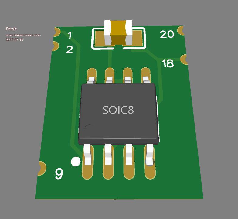 |
||||
| Page 1 of 2 |
|||||
| The Back Shed's forum code is written, and hosted, in Australia. | © JAQ Software 2026 |
