
|
|
Forum Index : Microcontroller and PC projects : Anyone REALLY good with electronic circuits?
| Page 1 of 2 |
|||||
| Author | Message | ||||
lew247 Guru Joined: 23/12/2015 Location: United KingdomPosts: 1709 |
Can someone take a look at this What I need to know is the output from Pin 25 on the FI1216 is it a dc voltage or a tone? I need to know what it is so I can figure out what kind of input to a Picomite I'm "guessing" it's a voltage that varies depending on signal strength because it goes to the analog input of the pic16f818 |
||||
| Amnesie Guru Joined: 30/06/2020 Location: GermanyPosts: 757 |
Hello, I looked at the schematics and the datasheet; on page 3 it says pin 25 is AF Sound Output, which is comming from the AM demodulator. "AF" probably means Audio Frequency. So it is no dc voltage but a normal ac tone signal. Datasheet: https://pdf1.alldatasheet.com/datasheet-pdf/view/96786/PHILIPS/FI1216MF.html Greetings Daniel Edited 2022-05-27 20:40 by Amnesie |
||||
| PeterB Guru Joined: 05/02/2015 Location: AustraliaPosts: 669 |
G'Day lew I am not an expert but the Philips F!1216 data indicates it is an audio tone. In one diagram it shows a capacitor connection to the outside world. But I am probably wrong �  Peter(B) I was a bit slow off the mark. P Edited 2022-05-27 20:42 by PeterB |
||||
| lew247 Guru Joined: 23/12/2015 Location: United KingdomPosts: 1709 |
It would normally be an audio tone yes but the demodulator chip TDA9800T has been replaced by an AD8307 logarhythmic amplifier which is why I'm uncertain what the actual output the pic is decoding, audio tone or dc / ac voltage |
||||
| Volhout Guru Joined: 05/03/2018 Location: NetherlandsPosts: 5927 |
Lew247, When the tda9800 is removed, this pin most likely is just a pin. Maybe that pin is connected to the output of the log amplifier that has replace the 9800. Sounds logical. For your project, where the tuner is used to look at a 4MHz spectrum, an audio output (200kHz bandwidth) does not make sense. And a demodulated audio output, with 15kHz bandwidth is even more unlikely. PicomiteVGA PETSCII ROBOTS |
||||
| lew247 Guru Joined: 23/12/2015 Location: United KingdomPosts: 1709 |
The output of the tuner IF (6Mhz bandwidth) goes to the input of the log amplifier where it's amplified and if any signals are detected the poutput of the log amplifier sends it to the output pin on the tuner I guess I'll just have to wait until the tuner arrives, swap the demodulator for the log amplifier, connect a 385Mhz antena and see what the output is when it detects a signal by connecting a volt meter to the output pin, I don't have a scope. |
||||
| PeterB Guru Joined: 05/02/2015 Location: AustraliaPosts: 669 |
Sorry Lew, I rushed in without giving enough attention to your description. I do that sort of thing. Looking at the FI1216 block diagram and guessing where the TDA9800 starts I would assume that your signal is an A.M. carrier modified by your new amplifier. And that sort of agrees with what the TDA9800 expects. Sorry that I'm not much help. Peter(B) |
||||
| Mixtel90 Guru Joined: 05/10/2019 Location: United KingdomPosts: 8904 |
According to the data sheet pin 25 is normal AF audio with pre-emphasis, but has a DC bias - like the output from a normal common emitter transistor stage (which it may well be). You have to put a capacitor from it (they suggest 33uF with + towards the chip) to get rid of the DC component followed by a 1k and 51nF de-emphasis (50us) RC filter. If you look at it on a scope you'll see DC shifted audio, with the capacitor & filter you can expect an audio signal of about 350mV. You can't connect pin 25 to a PicoMite as it can probably reach 5V with a 1k DC impedance. I would suggest turning it into an AF signal as described above then have an amplification stage (op-amp because you only have 350mV of audio at most) and clipping circuit (reversed pair of 2V4 zeners fed by a resistor) to get a cleanish square wave signal of 2-3V for the PicoMite if you are trying to detect a tone or tones. Edited 2022-05-28 17:10 by Mixtel90 Mick Zilog Inside! nascom.info for Nascom & Gemini Preliminary MMBasic docs & my PCB designs |
||||
TassyJim Guru Joined: 07/08/2011 Location: AustraliaPosts: 6538 |
The module is going to be modified. pin 25 will be the output of a log-amp. It is a DC voltage ranging from close to zero to a maximum of 3V depending on received signal strength. 25mV per dB Jim VK7JH MMedit |
||||
| Mixtel90 Guru Joined: 05/10/2019 Location: United KingdomPosts: 8904 |
Ah, once you modify it all bets are off. :) Mick Zilog Inside! nascom.info for Nascom & Gemini Preliminary MMBasic docs & my PCB designs |
||||
| PeterB Guru Joined: 05/02/2015 Location: AustraliaPosts: 669 |
Jim. What do you know that I don't? (and don't be rude  How do you know that it is a DC voltage? I'm not arguing just curious. It's all a bit beyond me. Peter(B) |
||||
| Mixtel90 Guru Joined: 05/10/2019 Location: United KingdomPosts: 8904 |
The link in the first post mentions mods to the tuner can, Peter. Mick Zilog Inside! nascom.info for Nascom & Gemini Preliminary MMBasic docs & my PCB designs |
||||
| PeterB Guru Joined: 05/02/2015 Location: AustraliaPosts: 669 |
Mick. I am totally confused by what is going on. Having never been a video type doesn't help but I thought my (old) general experience might do some good. Peter(B)  |
||||
| Mixtel90 Guru Joined: 05/10/2019 Location: United KingdomPosts: 8904 |
I know the feeling. :) I hadn't realised that the tuner was being modified either, as the original post simply asked what was on pin 25 of the beast. Mick Zilog Inside! nascom.info for Nascom & Gemini Preliminary MMBasic docs & my PCB designs |
||||
| lew247 Guru Joined: 23/12/2015 Location: United KingdomPosts: 1709 |
Apologies, I should have made it much clearer, I see things in my head what I want to know but it's really hard to put it into words most of the time After spending hours reading the datasheet of the AD8307 and trying to understand how it works with the output of the 6Mhz saw filter in the tuner I "think" I finally understand it It converts an RF signal to a DC voltage (I believe) In the datasheet it says Am I right in thinking that the maximum output of the AD8307 on the output pin is 2.5V and the voltage increases from 25mv for a very weak signal to 2.5v for a very strong one? Also with regard to the rf tuner What exactly does AGC "take over point" mean? 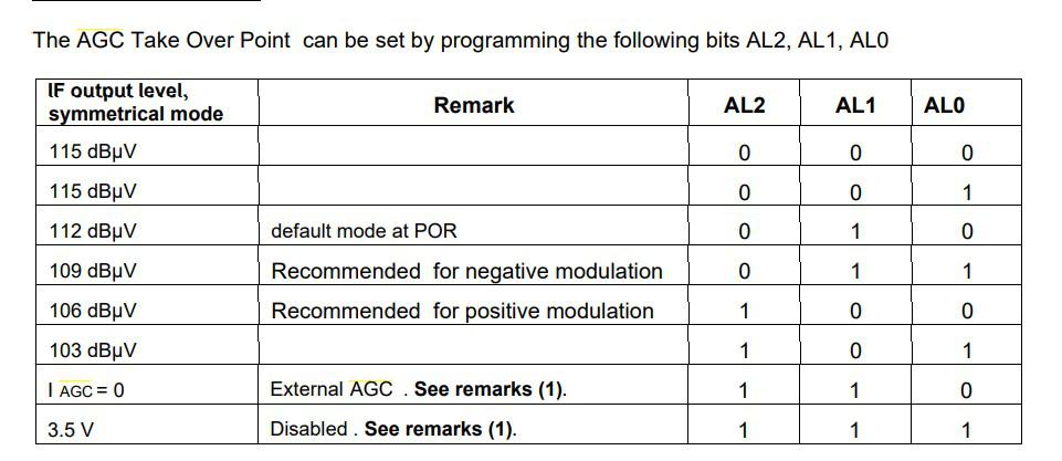 I want to be able to switch between wanting to hear strong signals and weak signals using the I2c bus I want to be able to switch between town strong signals due to lots of signals being recieved and I need the gain turned down to motorway driving where I need weak signal detection and the gain turned up high Am I right in thinking if I set the AGC pin to 115 dB�V then it will detect weaker signals better and if I set it to 103 dB�V it would be better if the signals were stronger and I need a weaker signal gain? Edited 2022-05-29 17:54 by lew247 |
||||
| phil99 Guru Joined: 11/02/2018 Location: AustraliaPosts: 3289 |
"............to 2.5v for a very strong one?" Yes, that is what I understand it to mean. If you wish to be cautious add a 1kR between it and the Pico with a shotkey diode from the Pico pin to 3.3V or a 2.7V zenner to ground. |
||||
| Mixtel90 Guru Joined: 05/10/2019 Location: United KingdomPosts: 8904 |
That's how it looks to me. 0.25V for -74dBm up to 2.5V at +16dBm. There's an internal 12.5k (nominal) resistor to ground on pin 4 and it varies the current through it at 2uA/dB (40uA/decade). I'm not sure, but you may have to treat it as a high impedance output and don't feed it into too low a resistance or accuracy will suffer. A non-inverting op-amp buffer might be an idea. The AGC seems to make sense - set it to 001 for max sensitivity and 101 for minimum. Edited 2022-05-29 18:01 by Mixtel90 Mick Zilog Inside! nascom.info for Nascom & Gemini Preliminary MMBasic docs & my PCB designs |
||||
| PeterB Guru Joined: 05/02/2015 Location: AustraliaPosts: 669 |
Lew et al. My goodness, we really are never too old to learn. I just assumed a log amp was just a non linear amp. At least you do seem to be making progress. Peter(B) |
||||
| lew247 Guru Joined: 23/12/2015 Location: United KingdomPosts: 1709 |
What's really frustrating for me, is I actually used to know all this beore my brain injury, I used to be a TV and radio engineer and actually traced faults and repaired to component level back in the 90's When I start something new these days, or have an idea for a project I have to basically re-teach myself everything which is exceptionally frustrating, knowing that if I then leave the project for a few months I'll have to start again. |
||||
| PeterB Guru Joined: 05/02/2015 Location: AustraliaPosts: 669 |
Lew. You really do have my sympathy. I have to contend with old age. recently I was trying to help tinine with a problem and I decided I needed simultaneous equations......simul what? I even had trouble spelling it. And I start designing something and come across earlier work on the same thing. But it is still fun if a bit slow and there are a lot of good bloke on TBS who love a problem and are prepared to put up with my inane waffles. Enjoy what you can while you can because non of us know what the future holds. Peter(B) |
||||
| Page 1 of 2 |
|||||
| The Back Shed's forum code is written, and hosted, in Australia. | © JAQ Software 2026 |
