
|
|
Forum Index : Microcontroller and PC projects : PM: Confused about SYSTEM I2C and SETPIN sda,scl,I2C....
| Page 1 of 3 |
|||||
| Author | Message | ||||
Grogster Admin Group Joined: 31/12/2012 Location: New ZealandPosts: 9584 |
PM manual, page 32, RTC: OK, fine. But then in the I2C section, page 137, it states that: So....which one is it?  If I want to put an RTC on pins GP26 and GP27, and I use OPTION SYSTEM I2C to set those pins for the RTC, can I still use that I2C channel for other I2C things, or is it then locked forever to the RTC ONLY? I would like to be able to use the one I2C channel for BOTH an RTC module AND other I2C devices. I am working on a PM-based SSD1963 5" TFT design(basically a sort-of E100 replacement due to chip shortages), and I/O pins are VERY short in number, and I really only have this ONE I2C channel that I can use, so would like to be able to use it for both, rather then just have it locked to the RTC only. Can I use the SETPIN sda,scl,I2C2 command to set the I2C2 channel, and then just use the RTC commands and they will work, or am I snookered? Ideally, what I want to connect to this channel other then the RTC, is probably an EEPROM chip, but most likely an I2C I/O port expander chip to provide more I/O since most of the native I/O will be gobbled up by the parallel interface to the LCD, the touch and SD card support etc. Basically, I am using every single I/O pin on the PM module, and am still left wanting, so was hoping I could add an I2C port expander chip to the design, but it would HAVE to co-exist with the RTC module on the same channel is the thing. Smoke makes things work. When the smoke gets out, it stops! |
||||
| Volhout Guru Joined: 05/03/2018 Location: NetherlandsPosts: 5021 |
Hi Grogster, I can only speak for the VGA picomite, since that is what I have used lately. If you define OPTION SYSTEM I2C GP14,GP15 you have essentially initialized the I2C2 port (at 100kHz) on pins GP14 and GP15. You don't have to do this again. After that you can enable the RTC (if you have one) with OPTION RTC AUTO ENABLE (but you don't have to, if you have no RTC). Anyway, with the OPTION SYSTEM I2C set, you can immediately use it. No SETPIN required, no I2C2 OPEN needed. That is all performed in the OPTION SYSTEM I2C . Simply I2C2 WRITE, or I2C2 READ. Do not close the I2C2 port, or you will loose your RTC. There can only be 1 system I2C port, so the second I2C port (in above case I2C port 1) requires you to SETPIN and I2C OPEN. Volhout P.S. you are not the first one that is confused. Maybe it is something that can be "simplified". Putting it in the manual may not be a good idea, since often the question is asked on the forum before the manual is consulted. Edited 2022-08-23 21:49 by Volhout PicomiteVGA PETSCII ROBOTS |
||||
| Grogster Admin Group Joined: 31/12/2012 Location: New ZealandPosts: 9584 |
Glad I am not the only one to get confused by this! �  Once I understand it, I'll be fine then. �  So, lets say I OPTION SYSTEM I2C GP27,GP26, then can I use RTC SETTIME and RTC GETTIME as usual, and provided the RTC is on GP26 and GP27, that will work, and I can also use the standard I2C WRITE and I2C READ commands on the same I2C port, yes? If so, fab, and I can proceed along those lines. If not, I will have to think of something else. EDIT: Ahhh, OK. Re-reading your post I picked up on this, which I did not pick up on the first time through your post.  Edited 2022-08-23 22:06 by Grogster Smoke makes things work. When the smoke gets out, it stops! |
||||
DrifterNL Regular Member Joined: 27/09/2018 Location: NetherlandsPosts: 58 |
The system I2C bus as configured by OPTION SYSTEM I2C is still free to use (PicoMite User Manual page 78). You are using GP26 as SDA and GP27 as SCL which is the I2C2 bus (2nd I2C bus). By making this the system I2C bus means that it (I2C bus) is always set to the pins configured by OPTION SYSTEM I2C and the bus is also always open and can't be closed. To use the system I2C bus for other I2C devices all you need to use is in your software is I2C2 Write and I2C2 Read and of course MM.I2C. One thing to remember is that, I believe, the system I2C is set to 400KHz but I can't find the timeout value in the manual. � To use the non system I2C bus you will need to use the SETPIN sda, scl, I2C and I2C OPEN speed, timeout Edited 2022-08-23 22:33 by DrifterNL Floating Point Keeps Sinking Me! Back To Integer So I Don't Get Injured. |
||||
| Mixtel90 Guru Joined: 05/10/2019 Location: United KingdomPosts: 7815 |
The restriction with having only a SYSTEM I2C port available is that you are stuck with the default settings as you have no OPEN and CLOSE. It will always have to run in master mode at 100kHz and with (probably) 100ms timeout to suit the RTC. That's probably not a problem in most cases. Mick Zilog Inside! nascom.info for Nascom & Gemini Preliminary MMBasic docs & my PCB designs |
||||
| KenH Newbie Joined: 06/02/2022 Location: United KingdomPosts: 13 |
Co-incidentally, I came across the same problems yesterday. I have an RTC, EEPROM and PFC8574 I/O expander on GP20 and GP21 with Option System I2C GP20, GP21. The PFC8574 kept throwing errors. On investigation, the System I2C bus runs at 400KHz and the PFC8574 is only a 100KHz device. Page 43 of the manual: "The I2C based display controllers use the SYSTEM I2C pins as per the pinout for the specific device. Other I2C devices can share the bus subject to their addresses being unique. If an I2C display is configured it will not be necessary to "open" the I2C port for an additional device (I2C OPEN), I2C CLOSE is blocked, and all I2C devices must be capable of 400KHz operation." I tried closing the system I2C channel "Option System I2C disable" and using I2C OPEN at 100KHz on GP20 and GP21. That solved the PFC8574 problem, but I could not access the RTC as the commands only seem to work with Option System I2C. Page 32 of the manual: "In order to enable the RTC you first need to allocate the I2C pins to be used using the command: OPTION SYSTEM I2C SDApin, SCLpin" So it looks as though you want to use an RTC and 100KHz devices, you need to use 2 separate I2C busses. I have now moved the PFC8574 to the second I2C2 channel and all is well. Best wishes Ken |
||||
| Mixtel90 Guru Joined: 05/10/2019 Location: United KingdomPosts: 7815 |
Ah - sorry - I got mixed up between 100kHz and 400kHz for an RTC. :( Perhaps a little bit could be added to the OPTION SYSTEM I2C bit of the Commands section of the manual to state what the default settings will be? 400kHz, master, presumably 8 bits and, presumably, 100ms timeout. Mick Zilog Inside! nascom.info for Nascom & Gemini Preliminary MMBasic docs & my PCB designs |
||||
| Grogster Admin Group Joined: 31/12/2012 Location: New ZealandPosts: 9584 |
Thanks for all the extra replies chums, it has been very useful information for me.  I actually thought that the RTC modules were a 100kHz device. I did not think they ran at 400kHz, as it is only a clock, and only needs to exchange a handful of bytes, so one would not think that fast I2C would be required. Oh well. I'll keep looking at this some more, but I had an idea last night while lying in bed waiting to drift off to sleep, and that was to use a 2nd PM module - they are so cheap, and I can easily fit two of them on the 5" SSD1963 PCB footprint. Use one as the main processor, and use the 2nd one as a slave I/O device. The extra benefit of that, is that you get not only I/O, but extra I2C, serial, SPI and PWM channels of the 2nd PM module - much more feature-rich then just plain I/O. They could be linked with one of the two COM ports, as the COM ports have buffering, allowing commands to be easily automatically queued on BOTH modules, for processing inside a main loop. No need for a 3rd I2C IRQ line from a port expander, to tell the main PM that the port expander wants attention, so one more pin on the main PM saved. I might play with this idea a little too. Smoke makes things work. When the smoke gets out, it stops! |
||||
| Mixtel90 Guru Joined: 05/10/2019 Location: United KingdomPosts: 7815 |
You could, dare I say it, build a PicoMite Pear as a test bench for inter-Pico communication. :) Mick Zilog Inside! nascom.info for Nascom & Gemini Preliminary MMBasic docs & my PCB designs |
||||
| KenH Newbie Joined: 06/02/2022 Location: United KingdomPosts: 13 |
Of course, the other alternative is to just use I2C OPEN at 100KHz and access the RTC registers directly with the I2C read and write commands. Write small subs to write the RTC registers and read then and update $date and $time. Regards Ken |
||||
| Mixtel90 Guru Joined: 05/10/2019 Location: United KingdomPosts: 7815 |
Or use a Micromite as a high speed I2C I/O expander in not much more board space. You get more ADC for your buck than you do with a PicoMite. :) Mick Zilog Inside! nascom.info for Nascom & Gemini Preliminary MMBasic docs & my PCB designs |
||||
| Volhout Guru Joined: 05/03/2018 Location: NetherlandsPosts: 5021 |
Maybe this is something for the picomite bug list. The system I2C port needs to be 100kHz -or- the user manual must be adapted.  The DS1307 and M41T11 RTC chip cannot run at 400kHz. It's maximum is at 100kHz 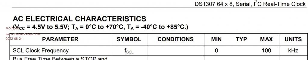 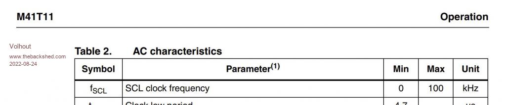 Edited 2022-08-24 18:51 by Volhout PicomiteVGA PETSCII ROBOTS |
||||
| Bleep Guru Joined: 09/01/2022 Location: United KingdomPosts: 622 |
Hi Volhout, Simple answer is to use the 3231, dirt cheap. https://www.ebay.co.uk/itm/224582710859?hash=item344a2c364b:g:1D4AAOSwU-ZhIzu4 I bought 3 for �7.50 from China. All work great on the Picomite with standard setup and settings. Regards, Kevin. |
||||
| lizby Guru Joined: 17/05/2016 Location: United StatesPosts: 3347 |
Check out this thread for serial control of a picomite. It's specifically about MMBasic for Windows, but has been tested using an picomite as a controller. It can either gather data sent by another picomite or directly control the other picomite by sending commands for it to execute from the ">" prompt as if the controlling picomite was a human at the keyboard--that's with no user MMBasic program running at all on the second picomite, but you can also have a user program and run commands sent from the controller using the EXECUTE command. Wired up, have yet to test. PicoMite, Armmite F4, SensorKits, MMBasic Hardware, Games, etc. on fruitoftheshed |
||||
| DrifterNL Regular Member Joined: 27/09/2018 Location: NetherlandsPosts: 58 |
About the 3231 module in the link. I read under Module Parameters that the module accepts a CR2032 or LiR2032. The module has a small battery charging circuit on the board and thus unmodified uses the LiR2032 which is a chargeable 2032. To use a CR2032 I read online somewhere that the red diode on the module needs to be removed which disables the charging circuit. Edited 2022-08-24 22:34 by DrifterNL Floating Point Keeps Sinking Me! Back To Integer So I Don't Get Injured. |
||||
| lizby Guru Joined: 17/05/2016 Location: United StatesPosts: 3347 |
Even simpler and smaller aliex DS3231 module A number of Mick's Picomite PCBs (and those of other people) use these. PicoMite, Armmite F4, SensorKits, MMBasic Hardware, Games, etc. on fruitoftheshed |
||||
| Volhout Guru Joined: 05/03/2018 Location: NetherlandsPosts: 5021 |
I appreciate your suggestions, but my point is that we have a mismatch between the user manual, that advocates a DS1307, and the firmware that will not work with a DS1307. Geoff and Peter have to align user manual and firmware. Same for the M41T11 chip. The DS3231, DS3232 and the PCF8563 are fine Volhout Edited 2022-08-25 16:30 by Volhout PicomiteVGA PETSCII ROBOTS |
||||
TassyJim Guru Joined: 07/08/2011 Location: AustraliaPosts: 6264 |
I agree that the manual needs attention but due to the rather poor timekeeping accuracy of the DS1307, any reference to it should be dropped or at least a warning. Jim VK7JH MMedit |
||||
| phil99 Guru Joined: 11/02/2018 Location: AustraliaPosts: 2578 |
Re DS1307 I have one from Jaycar working on PicoMite 5.07.05b17 but as Jim says it's accuracy is dismal. option list OPTION SYSTEM SPI GP18,GP19,GP16 OPTION SYSTEM I2C GP8,GP9 OPTION CPUSPEED (KHz) 378000 OPTION DISPLAY 55, 120 OPTION LCDPANEL ILI9488, RLANDSCAPE,GP15,GP14,GP13,GP7 OPTION TOUCH GP12,GP11 GUI CALIBRATE 0, 3820, 408, -1306, 946 OPTION SDCARD GP22 > rtc gettime > > ? datetime$(now) 26-08-2022 08:53:43 > The RTC command presumably tests typical I2C RTC speeds and addresses to find the right one. Edited 2022-08-26 10:20 by phil99 |
||||
| Grogster Admin Group Joined: 31/12/2012 Location: New ZealandPosts: 9584 |
I agree with the others here about the 1307. It is a HORRIBLE chip by today's standards, and when 3232 or 3231 chips are easy and cheap to get now.... I would personally never use a 1307 in ANY project, cos they are so inaccurate. They were fine to support at the time that 3232 or 3231 chips were very expensive by comparison, but now they are very cheap. Most RTC modules on AliExpress or eBay use them now, and while they might likely be clones, I have never had any issues with them and they always work for me, making the drifty-as-hell 1307 a bit pointless now I would think. My 2c only. Smoke makes things work. When the smoke gets out, it stops! |
||||
| Page 1 of 3 |
|||||
| The Back Shed's forum code is written, and hosted, in Australia. | © JAQ Software 2025 |
