
|
|
Forum Index : Microcontroller and PC projects : PM: 2.8" LCD board for the PM...
| Page 1 of 2 |
|||||
| Author | Message | ||||
Grogster Admin Group Joined: 31/12/2012 Location: New ZealandPosts: 9592 |
Hi all. Cos I needed a board to drive a 2.8" SPI LCD with the PM, I came up with this board that piggy-backs onto a standard 2.8" SPI module with touch: 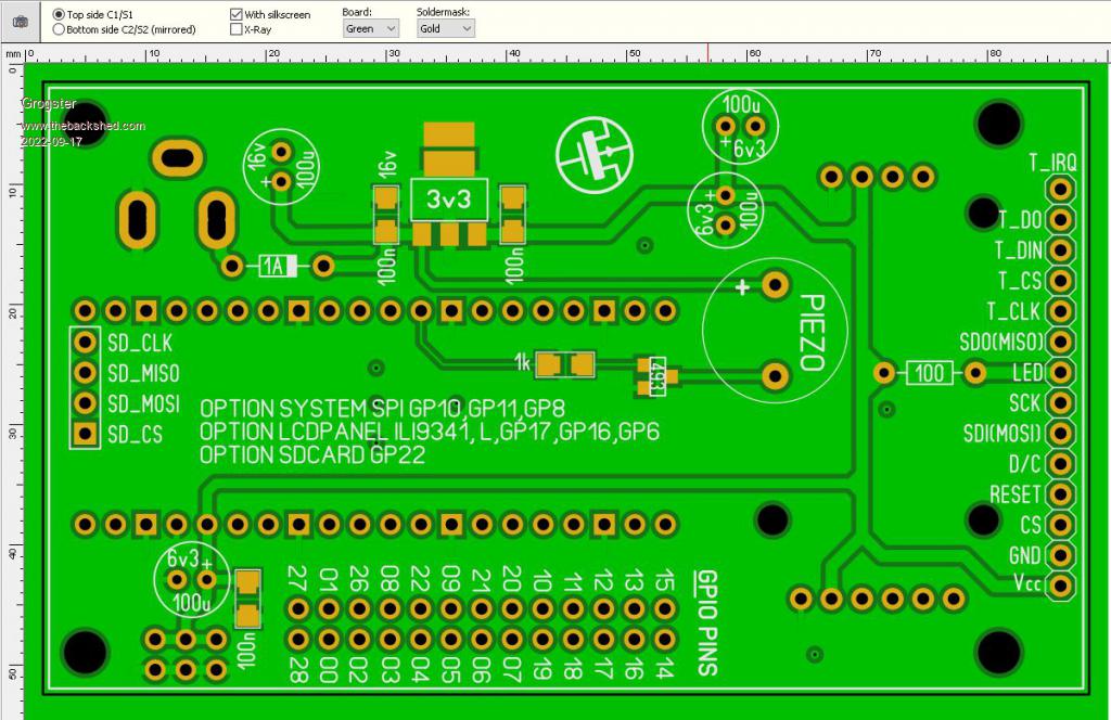 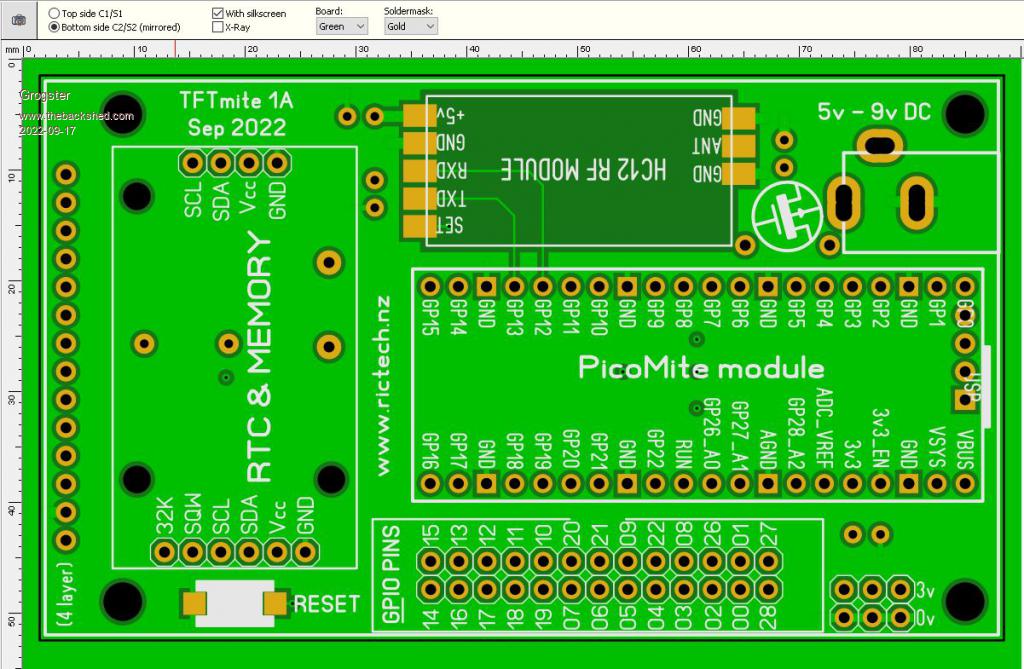 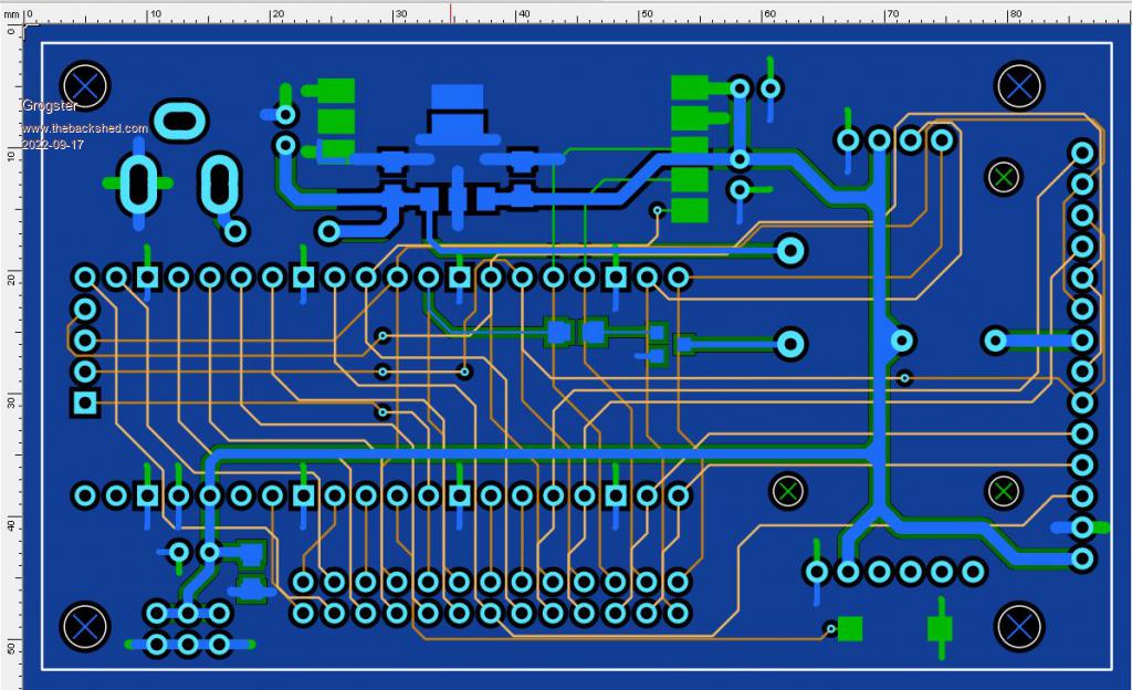 The board is four-layer. �Four-layer boards used to be very expensive compared to double-sided, but these days, that is not the case. �These four-layer designs cost a whole two bucks more then the standard double-sided price. �Seven bucks for five vs five bucks if it were double-sided, so it makes sense to simply go directly to four-layer if it is easier to route everything, and it is on this size. All PM pins are routed out to a box-header. �2x3 header for 3v3 and ground connections for experimenters. �RTC module with EEPROM memory chip, HC12 wireless module, linear LDO regulator, piezo sounder and reset button all on-board. With the aid of a daughterboard, you could easily add anything else you wanted to to the PCB stack such as the LPF for audio out or a PWM motor driver or something like that. Needs 9v DC supply if you want to use the piezo, as they don't tend to "Start" on 5v or less, but if you KNOW you won't be using the piezo or the GUI touch click sound, then you can run the board from 5v. EDIT: Forgot to add the OPTION TOUCH command to the silkscreen, but I will be doing that shortly. Edited 2022-09-17 20:09 by Grogster Smoke makes things work. When the smoke gets out, it stops! |
||||
| Mixtel90 Guru Joined: 05/10/2019 Location: United KingdomPosts: 7858 |
That's very neat! I've not attempted 4-layer yet. Well, not for anything other than a bit of playing. I'm not suggesting this as a change, but if a spare GPIO pin was available it could PWM a charge pump or even a very simple SMPS to get sufficient voltage for a piezo. As GP25 is only useful for driving the base of a transistor it might be a good use for the latter. I must look into that... Edited 2022-09-17 20:19 by Mixtel90 Mick Zilog Inside! nascom.info for Nascom & Gemini Preliminary MMBasic docs & my PCB designs |
||||
| Volhout Guru Joined: 05/03/2018 Location: NetherlandsPosts: 5056 |
Hi Grogster, Are you sure 3V3 is sufficient to light backlight. ? I always used 5V with a resistor. Volhout PicomiteVGA PETSCII ROBOTS |
||||
| Grogster Admin Group Joined: 31/12/2012 Location: New ZealandPosts: 9592 |
Deleted your duplicate post. I normally use 5v also, but I have hooked up an LCD and 3v3 works fine for the backlight. At least on the 2.8" SPI LCD anyway. Perhaps NOT on the bigger 5" or 7" LCD's, but we're not using either of those.  With a 27R series resistor, the LCD is quite bright - even on 3v3. Smoke makes things work. When the smoke gets out, it stops! |
||||
palcal Guru Joined: 12/10/2011 Location: AustraliaPosts: 1986 |
I seem to remember there is some configuration on the back of the LCD, a 3.3v reg. to run off 5V. and it can be shorted out for 3.3V. "It is better to be ignorant and ask a stupid question than to be plain Stupid and not ask at all" |
||||
| Grogster Admin Group Joined: 31/12/2012 Location: New ZealandPosts: 9592 |
Yes, you are correct. "J1" - solder-blob it to bypass the on-board 3v3 regulator and run the display from an external 3v3. The LED connection is separate from that though. Smoke makes things work. When the smoke gets out, it stops! |
||||
| Glen0 Regular Member Joined: 12/10/2014 Location: New ZealandPosts: 95 |
Looks very nice thanks, I would like to get my hands on a few as soon as the board is ready. I Recall way back that there was an issue with dodgy HC-12 modules on the market. Is this still the case and if so can you suggest/recommend a supplier. Are you expecting to stock up in the near future? |
||||
| Grogster Admin Group Joined: 31/12/2012 Location: New ZealandPosts: 9592 |
Howdy Glen. Yes, I will be getting at least five boards to experiment on, but I could get ten boards if I know you would like some. Yes, the dodgy HC12's are an issue. Basically, any that are being offered for US$3 or so, are bound to be clones, so avoid those listings like the plague. I have a contact at the factory now, and order direct from the manufacturer to ensure they are genuine. But even the people making the HC12's are having issues with chip shortages. I got some recently, but only a small batch, and I have them already reserved for other things which is why the website still lists them as sold-out, but if you were after a couple, I can spare a few. Genuine ones now have the HC logo laser-engraved into the top of the crystal package. This is something that costs money to have done, so no cloners are going to go to the cost to have that done on what seem to be rejected crystals anyway. So, keep a close eye on the crystal on the HC12. If it has the HC12 logo lasered into it, the module will be genuine. Clones won't have the logo on the crystal package. I note that with the latest HC12's I got, the MCU has changed back from a QFN package, to the SSOP that the module originally had on it. My guess would be cos the QFN chip is hard to get at the moment, but perhaps they were able to buy stock of the SSOP chip. These modules still have the laser-engraved HC logo on the crystal though. Smoke makes things work. When the smoke gets out, it stops! |
||||
| Glen0 Regular Member Joined: 12/10/2014 Location: New ZealandPosts: 95 |
Yes I am definitely keen to get some. What's the minimum number of boards you would be prepared to supply to me and roughly how much are they each? Cheers |
||||
Quazee137 Guru Joined: 07/08/2016 Location: United StatesPosts: 593 |
This is GREAT. Inline with a change over I have been working on. It'll be a good jumping off board to do some testing. A header cable wired to match the RPi header and test my RPi hats on the pico. Using the RPi 3.5" display on my testing jig but haven't got around to the 2.8"s. I have a board I'm working on that has the chip and not the pico board. Waiting for your testing of them. I'll need to make five. Who is your order from? JLPC  I hope. I hope.Thanks Quazee137 |
||||
| Grogster Admin Group Joined: 31/12/2012 Location: New ZealandPosts: 9592 |
@ Glen - Please PM me or email me and we can discuss your needs as I have not yet placed the order, so it would be the perfect time to incorporate you. I'm not interested in profiting from this, so on-sell at cost price. For ten boards, JLCPCB are currently charging US$7 but more will probably affect the price, so we need to talk about your needs. Please remember that this is the 1A design - the prototype - so before you get too excited and order heaps, we probably should prove the design with a small number of test boards before you commit to a large quantity of PCB's if you catch my drift. @ Quazee137 - Yes, I get everything through JLCPCB these days. Assembled or not. Smoke makes things work. When the smoke gets out, it stops! |
||||
| Grogster Admin Group Joined: 31/12/2012 Location: New ZealandPosts: 9592 |
Quick update on this thing: Built one, and tested all the major aspects of it, and it works fine. 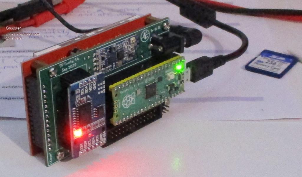 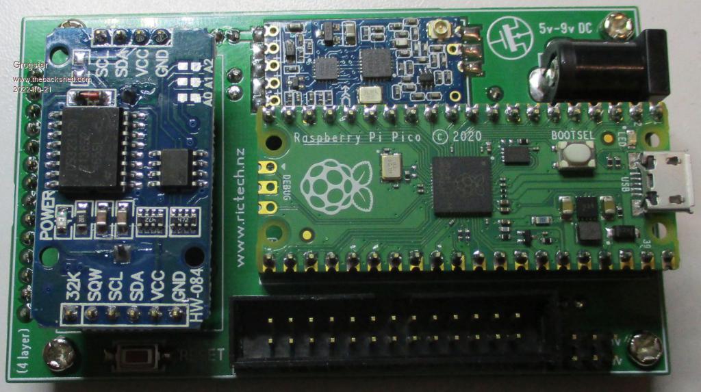 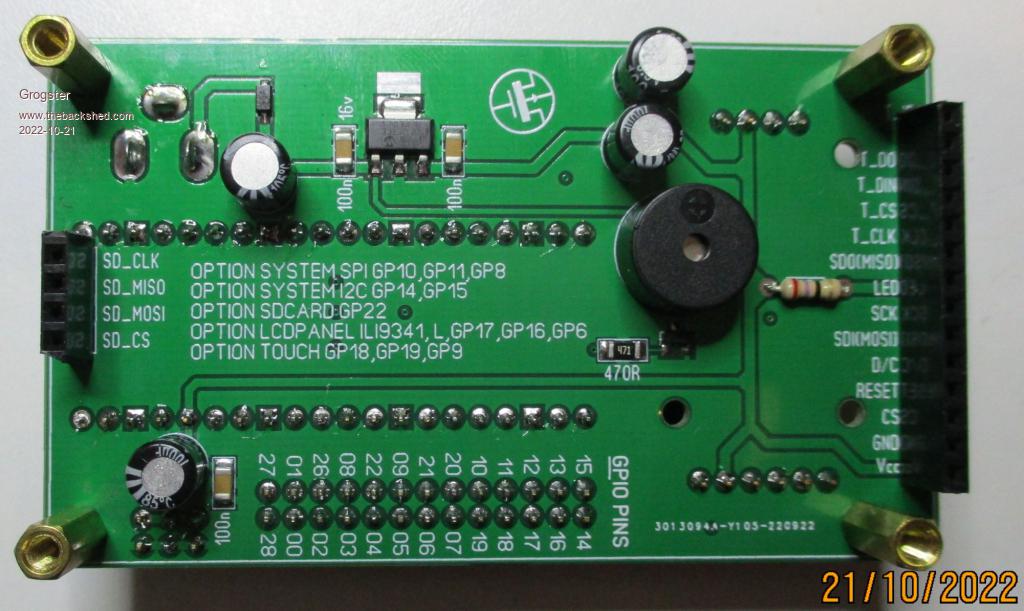 One thing I did note, is that the PM SD card handler REALLY does not like the 1k series resistors on these LCD panels! Reading from the card works fine, but any attempt to write or save to the card causes a low-level filesystem hard error(not verbatim - I forget EXACTLY how it was worded). This error is bad enough, to totally corrupt the SD card, and you have to reformat the card to use it again. I have heard of people having this issue before, when they use any modular type of SD card connection, that has anything at all in series with the SPI connections. This is also the case here, so one thing that has to happen, is those 1k resistors need to be removed and replaced with zero-ohm ones or just wire links. Once you do that, writing works just fine. 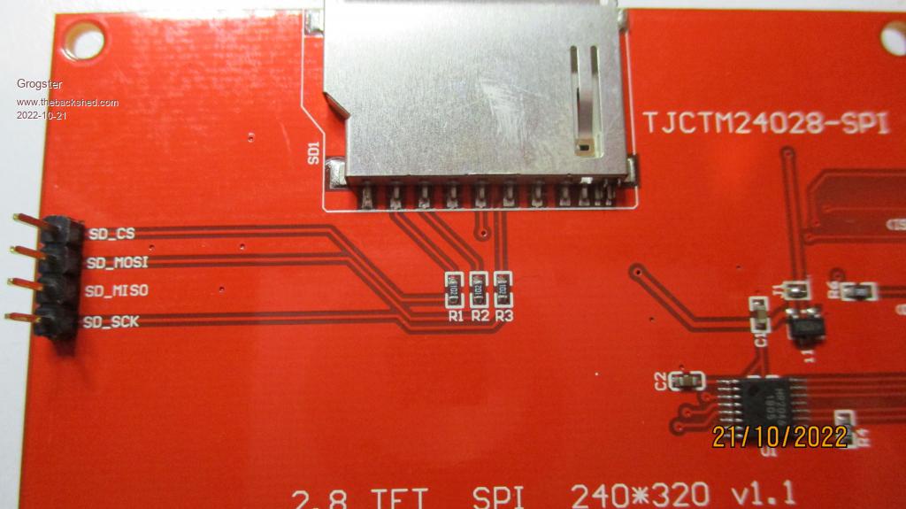 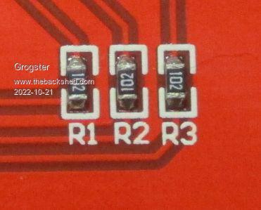 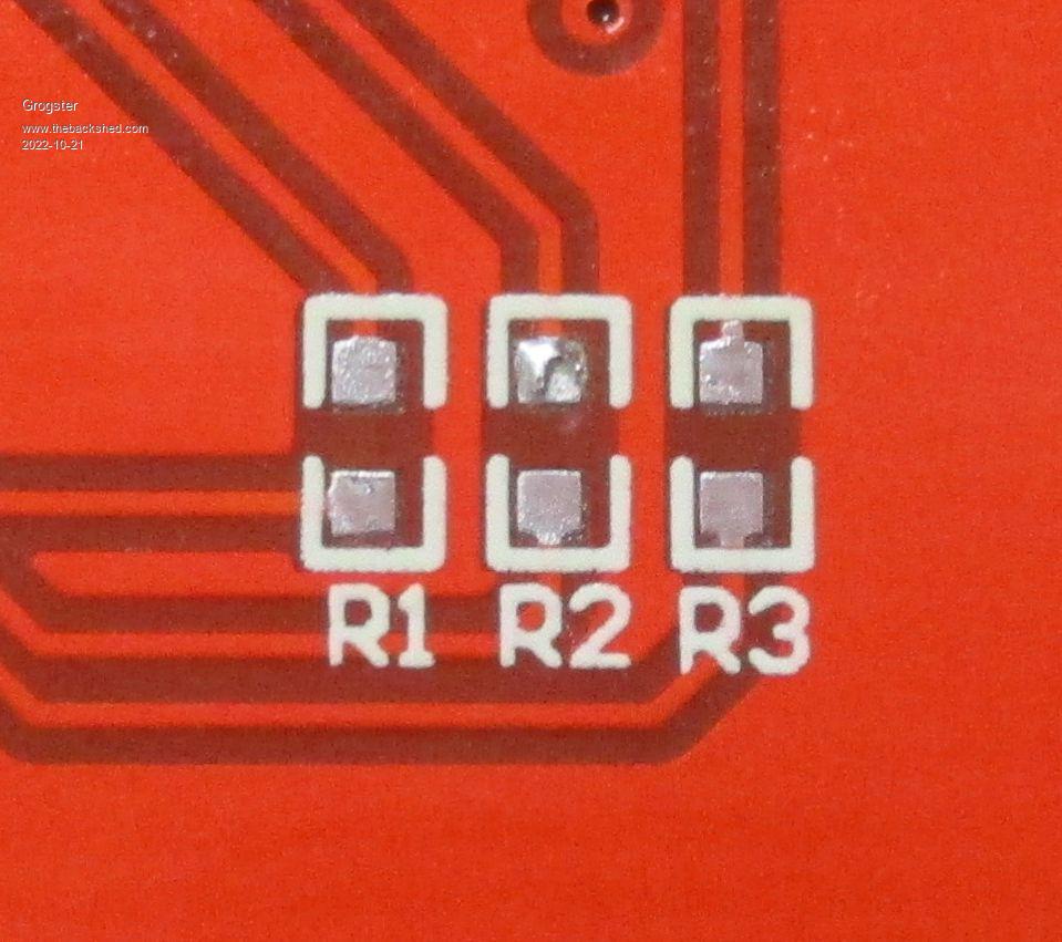 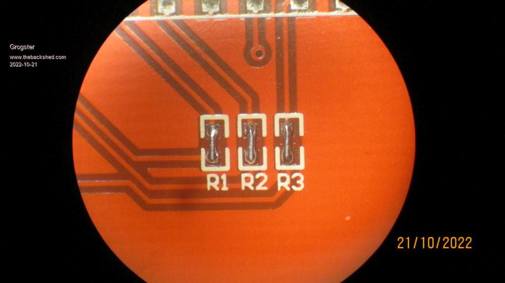 Interestingly, there are 1k resistors(R1,R2,R3) in series with SD_CS, SD_CLK and SD_MOSI, but there is no resistor in series with SD_MISO, so you end up with a kind of "Unbalanced" SPI bus. This does not seem to bother Micromite series chips, but the RP2040 really does not like the taste of those series resistors, so they MUST be removed. That will be true for pretty much ALL LCD modules where there are series resistors in the SD card SPI lines. Smoke makes things work. When the smoke gets out, it stops! |
||||
| Glen0 Regular Member Joined: 12/10/2014 Location: New ZealandPosts: 95 |
Looks good. These LCD boards seem to have lots of different quirky problems. I have some 2.8" LCD's and HC12's arriving early December. Noticed how you soldered the HC12 directly to the main board. What is the 3V3 regulator you are using for this board. I will order some of them, the SMD caps and the power connectors. Where do you usually source these components. Cheers |
||||
| Hans Senior Member Joined: 18/10/2022 Location: CanadaPosts: 116 |
@Grogster Hello; Some curious questions ... The RTC you are using has some flash memory at Hex57, have you been able to read/write to it? If you have, do you have any published code you can share? The Pico W has an RF chip on it, do you know, has anyone tried utilizing that instead of adding a separate RF board? Thanks, Hans ...  |
||||
| palcal Guru Joined: 12/10/2011 Location: AustraliaPosts: 1986 |
This is not my code, not sure if it was all by TBS member Twofingers. DS3231 EPROM.zip "It is better to be ignorant and ask a stupid question than to be plain Stupid and not ask at all" |
||||
| Grogster Admin Group Joined: 31/12/2012 Location: New ZealandPosts: 9592 |
Howdy. Regulator is Microchip MCP1703A-33: LINK Microchip don't have any in stock at the moment - stupid frustrating silicon shortages.  I normally get Microchip parts from Microchip Direct, but as they are out, you can find most other stuff from Element14 or mouser. Element14 list this reg as out of stock at the moment, BUT - they will have about two and a half thousand of them next month, so their website says... LINK I do have a few of these in stock though, so if you wanted any desperately urgently, I can provide you with some. SMD caps and 470R resistor are 1206 footprint, from any supplier you like. The electros are low-profile MCMHR series ones(7mm height) such as these ones here: 100uF 6v3 100uF 16v These caps are in stock now. I think that is all the special parts. RTC modules are standard from eBay or AliExpress for about two bucks each: LINK You need to remove the right-angle pin-header, and replace it with standard straight ones, then it plugs directly into the host PCB. DC socket and 3mm mounting hardware are standard - get them anywhere you like. Piezo is standard 12mm type - get them anywhere you like. I got lower-profile ones that fit better under the LCD then the ones from Jaycar, which are taller(and more expensive): LINK Despite these only being 14c each, they have always worked fine for me, but you know the old saying - "Buyer beware".... EDIT: @ Hans - No, I've never used the EEPROM chip on these RTC's, but I expect the code Paul posted should work - MMBASIC is very good at writing to those type of EEPROM chips, and I remember seeing heaps of threads over the years of people playing with them - myself included(but not on these modules). Looking close at the RTC module now, the EEPROM chip is a 24C32. This has been brought up before on the forums, but Peter(matherp - the lead developer of the PicoMite code) has said that the W variant of the Pico board will NOT be supported due to complications with interfacing to it from what I remember. The Pico-W board is not officially supported, so MMBASIC SHOULD run just fine on it, but no guarantees and definitely no WiFi support. For now, anyway. Peter has a habit of saying no, then surprising us all with a code that works. But don't get your hopes up. Edited 2022-10-23 15:04 by Grogster Smoke makes things work. When the smoke gets out, it stops! |
||||
| palcal Guru Joined: 12/10/2011 Location: AustraliaPosts: 1986 |
Grogster said I have used the code for years on a DS3231 to save data and it works fine. "It is better to be ignorant and ask a stupid question than to be plain Stupid and not ask at all" |
||||
| Mixtel90 Guru Joined: 05/10/2019 Location: United KingdomPosts: 7858 |
...it saves data just fine but it's a one-way trip! WOM data sheet (link to a PDF) Edited 2022-10-23 17:02 by Mixtel90 Mick Zilog Inside! nascom.info for Nascom & Gemini Preliminary MMBasic docs & my PCB designs |
||||
| phil99 Guru Joined: 11/02/2018 Location: AustraliaPosts: 2608 |
It functions very much like my memory. Chip availability April 1 ? The cooling requirement is interesting. |
||||
| Hans Senior Member Joined: 18/10/2022 Location: CanadaPosts: 116 |
Paul; Thanks so much for the code.  I will put it to good use! I will put it to good use!Hans ... |
||||
| Page 1 of 2 |
|||||
| The Back Shed's forum code is written, and hosted, in Australia. | © JAQ Software 2025 |
