|

|
Forum Index : Microcontroller and PC projects : PicoMite: what the monkey made
| Page 1 of 3 |
|||||
| Author | Message | ||||
| thwill Guru Joined: 16/09/2019 Location: United KingdomPosts: 4344 |
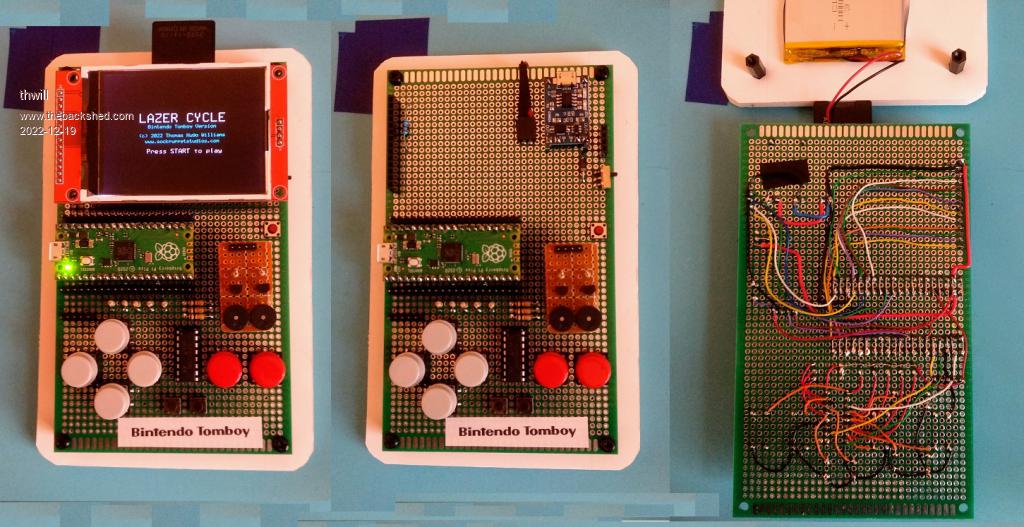
Hi folks, I had planned to defer sharing until I had a schematic and maybe a video made, but I failed to be that patient:  Thanks to everyone who helped, even if they didn't know that they were, especially @Volhout (audio), @Mixtel90 (I borrowed the backpack schematic for much of the layout) and @Turbo46 (encouragement). Apologies for the dreadful photo lighting / editing. Best wishes, Tom MMBasic for Linux, Game*Mite, CMM2 Welcome Tape, Creaky old text adventures |
||||
| IanRogers Senior Member Joined: 09/12/2022 Location: United KingdomPosts: 152 |
Looks really good..  On my pico system the pico is under the screen ( like the micromite backpack ) Just shows how versatile these things are.. Well done.... Ian I'd give my left arm to be ambidextrous |
||||
| Martin H. Guru Joined: 04/06/2022 Location: GermanyPosts: 1357 |
a original Tomboy  hope you'll get PicoVaders running   Edited 2022-12-20 00:28 by Martin H. 'no comment |
||||
| thwill Guru Joined: 16/09/2019 Location: United KingdomPosts: 4344 |
I did, it does  . .Tom Edited 2022-12-20 00:30 by thwill MMBasic for Linux, Game*Mite, CMM2 Welcome Tape, Creaky old text adventures |
||||
| Volhout Guru Joined: 05/03/2018 Location: NetherlandsPosts: 5703 |
With integrated NES controller... WAUW... Nice work Tom !! Looking at the pictures, I guess the battery is under the display, not leaving much room for the picomite... When possible, show a video of the Bintendo Tomboy in operation... PicomiteVGA PETSCII ROBOTS |
||||
| Mixtel90 Guru Joined: 05/10/2019 Location: United KingdomPosts: 8564 |
Yay! I love it! :) Especially good for a non-hardware bod. Congratulations. :) Mick Zilog Inside! nascom.info for Nascom & Gemini Preliminary MMBasic docs & my PCB designs |
||||
| thwill Guru Joined: 16/09/2019 Location: United KingdomPosts: 4344 |
An affectation, the Pico has enough GPIO that I could have just wired up the buttons directly. Thanks  The battery is under the protoboard taped to the piece of foamboard that currently serves as the "enclosure". I think there is space under the screen to squeeze in the PicoMite, a micro-sd, the charger module and the amp module (once I've chosen one - the current "buzzer" setup is just a temporary expedient to "complete" this prototype) and then compact the whole device onto a 100x100mm PCB - my next step with the h/w once all the bits arrive. That's the plan, but I want to put in the extra effort to make a proper video (rather than a quick single-take recording) so as to potentially attract a wider audience. Best wishes, Tom MMBasic for Linux, Game*Mite, CMM2 Welcome Tape, Creaky old text adventures |
||||
| Mixtel90 Guru Joined: 05/10/2019 Location: United KingdomPosts: 8564 |
When you said a 100x100 PCB I thought of my MachiKani layout... Maybe a rehash of it is on the cards. :) Mick Zilog Inside! nascom.info for Nascom & Gemini Preliminary MMBasic docs & my PCB designs |
||||
| thwill Guru Joined: 16/09/2019 Location: United KingdomPosts: 4344 |
If I'm honest this is why I didn't discuss my project earlier and was loath to do so even now except for the little voice in the monkey's head that wanted to "show off" the tricks it had learnt ... I knew you could knock off a PCB faster than I could type the letters 'P', 'C', 'B' and was hoping to do it for myself    . .Best wishes, Tom MMBasic for Linux, Game*Mite, CMM2 Welcome Tape, Creaky old text adventures |
||||
| Mixtel90 Guru Joined: 05/10/2019 Location: United KingdomPosts: 8564 |
You're quite welcome to do so! :) I'll send you my SL6 file if you like and you can have a go at modifying it. It might give you a good start. I'd suggest moving the display slightly further "up" the PCB, although you may need to find a thinner speaker.sounder to do so. An idea there might be to use one of the thin piezo elements (the flat ones) and glue it to either the bottom of the case or, if tracks allow, to the bottom of the PCB. The SD card might be able to go on the underneath of the PCB, underneath the Pico (which is surface mounted). Getting the height of the display correct to fit the case will require a little thought. EDIT I think this needs: a) a longer connector for the display in order to get it close enough to the box lid. It may be possible to use a through-hole PicoMite with this. b) a daughter pcb on pillars to get the buttons close enough to the lid of the box. c) the display moving "up" as far as reasonably possible to make more room for the buttons at the bottom. d) as far as I can tell from looking at a box, it would be possible to fit the SD card holder under the PCB (but probably not the battery). e) it *might* be possible to fit a SMD Pico under the PCB, which would make plenty of space under the display for the battery. I've not measured anything. All of these ideas mean a (more or less) complete change of layout so there's plenty for you to do. :) Note though that at the moment the centre line of the display is very close to the centre line of the PCB and box so there's no need to change its horizontal position. Edited 2022-12-20 05:17 by Mixtel90 Mick Zilog Inside! nascom.info for Nascom & Gemini Preliminary MMBasic docs & my PCB designs |
||||
| thwill Guru Joined: 16/09/2019 Location: United KingdomPosts: 4344 |
Thanks Mick, I was (mostly) just kidding, I don't have a monopoly on this so knock yourself out, in any case my design is highly derivative of your work. I'm intending to start from scratch using EasyEDA (which I have some familiarity with for schematics) and the only enclosure I'm worried about is a two layer PCB or acrylic "sandwich". If/when I've cocked it up a couple of times I may defer to a helpful guru to design a PCB. Best wishes, Tom MMBasic for Linux, Game*Mite, CMM2 Welcome Tape, Creaky old text adventures |
||||
| Mixtel90 Guru Joined: 05/10/2019 Location: United KingdomPosts: 8564 |
If you grab the Hammond drawing for the 1593 case you'll be able to use the same PCB size, notches and fixing centres for your PCB. That will make things a lot easier later should you decide to use a "proper" case. I may not be doing much for a while yet. I have my record deck in pieces, undergoing a big upgrade and re-build. :) Vinyl rules! Mick Zilog Inside! nascom.info for Nascom & Gemini Preliminary MMBasic docs & my PCB designs |
||||
| Hans Senior Member Joined: 18/10/2022 Location: CanadaPosts: 117 |
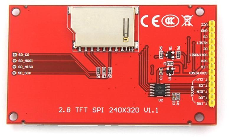
@thwill Hi Tom; Just received one of those displays (ILI9341). I bodged up the SD Card part and works great. Do you have a schematic or just a list of Pico pins to the display connector you could please share? I searched and while there was a huge discussion about ILI9488 not working, it only referenced the ILI9341 controller which has different pin designations. A picture of the connections on my board;  Thanks in advance for any help from the group. Hans ...  |
||||
| matherp Guru Joined: 11/12/2012 Location: United KingdomPosts: 10965 |
manual "Example LCD Panel Configuration" |
||||
| Hans Senior Member Joined: 18/10/2022 Location: CanadaPosts: 117 |
Thanks I knew I saw the details somewhere but I just could not remember where. Page 47 is exactly what I was looking for.  Again thanks Peter and a Merry Christmas to you and your loved ones  . .Hans ...  |
||||
| Turbo46 Guru Joined: 24/12/2017 Location: AustraliaPosts: 1663 |
Hardly a monkey Tom. I'd like to see a demo too. If you make a video I hope you can find something better for the sound than those buzzers. I'll be very interested to see what other games you produce for it. I just may have to build one.  Bill Keep safe. Live long and prosper. |
||||
| Turbo46 Guru Joined: 24/12/2017 Location: AustraliaPosts: 1663 |
@Volhout, I thought that you may like to design a filter especially to suit the Tomboy. I have looked at the music and sounds that Tom uses and all of them are under 5kHz (the highest frequency on an 88 key piano is 4186Hz). There are no intentional harmonics as when a musical instrument is played I believe. I believe that the PLAY SOUND is used to play sine waves but I see that 'TYPE O' and 'TYPE S' are used but I cannot find out their meaning in any manual. Anyone? Maybe type O is 'off', type S is sine but I don't know? Can one channel have two or more types of wave form or do you use different channels for the different waveforms? I hope that type 'S' is not square wave because this post is largely meaningless. For the digital amplifiers that he intends to use the best I can find is an input impedance of >22k. That would be less if he has the need for a volume control. I would have thought that a simple two stage passive RC filter (12dB per octave) that begins to roll off at 5kHz with capacitive coupling to the amplifier input would be sufficient. I'd be interested in your thoughts. Bill Keep safe. Live long and prosper. |
||||
| Volhout Guru Joined: 05/03/2018 Location: NetherlandsPosts: 5703 |
Hi Tom, The picomiteVGA manual shows your sound options...  I'll see what I can do for the filter/amplifier. Do you envision one of this digital amplifiers, and need a simple filter between pico and the digital amplifier ? Or do you want the whole circuit designed (including the amplifier).? Volhout PicomiteVGA PETSCII ROBOTS |
||||
| Turbo46 Guru Joined: 24/12/2017 Location: AustraliaPosts: 1663 |
Hi Volhout, It's me asking about the filter. I have discussed it with Tom and he is happy with my request. He has ordered two different digital amplifier modules to try as far as I know. Clearly I do not have the latest manual (I thought I did) but it's not in the CMM2 manual? Found it in the Draft PicomiteVGA manual thanks. Bill Keep safe. Live long and prosper. |
||||
| matherp Guru Joined: 11/12/2012 Location: United KingdomPosts: 10965 |
Page 99 (Adobe page) of CMM2 manual as downloaded from Geoff's site Edited 2022-12-21 18:39 by matherp |
||||
| Page 1 of 3 |
|||||
| The Back Shed's forum code is written, and hosted, in Australia. | © JAQ Software 2026 |