Notice. New forum software under development. It's going to miss a few functions and look a bit ugly for a while, but I'm working on it full time now as the old forum was too unstable. Couple days, all good. If you notice any issues, please contact me.
Murphy's friend Guru Joined: 04/10/2019 Location: AustraliaPosts: 593
Posted: 08:26am 14 Jan 2023
Copy link to clipboard
Print this post
Mike, if you are into saturation testing it may be worthwhile to search 'warpspeed' for that topic. He came up with a very neat design that bounces charge back and forth between the choke coil and a capacitor, thus requiring little power supply current to achieve saturation.
I built one and have used it with every choke I made (quite a few ).
KeepIS Guru Joined: 13/10/2014 Location: AustraliaPosts: 1394
Posted: 09:36am 14 Jan 2023
Copy link to clipboard
Print this post
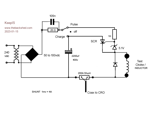
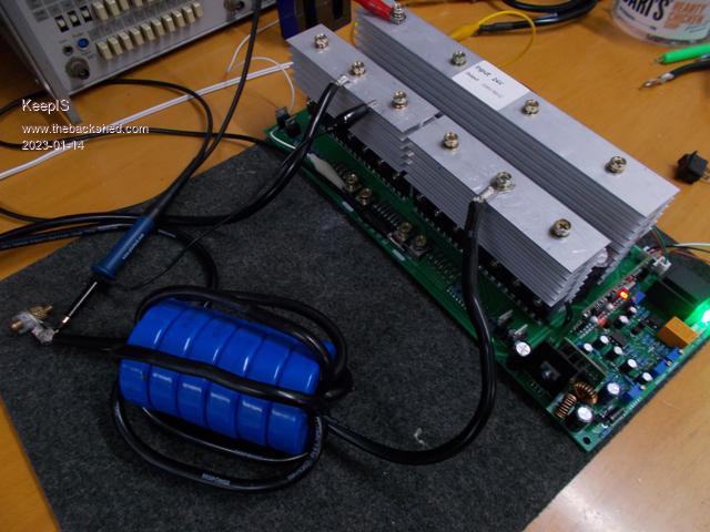
Thanks, I saw that great tester, but this method has been used for ever and was quick to make, the power supply does nothing except charge the CAP via a 20 ohm resistor. The cap can easily dump over 1000 Amperes into the inductor.
The big Transformer on the test Jig is just one I had lying around, and it gave me almost 100v to the Cap - really only need around 50V. � However, I found I needed a .47uf cap to stop noise on the SCR trigger from the supply, once I did that I got really clean signals.
I was just about to post a few more shots when I noticed Solar Mike post a link and some info on the Blue toriod, thanks for that, really appreciated.
I unwound the other 3 blue toriods I had and placed 6 turns through the 6 toriod stack. I measured 45uH and very high saturation, fitted it to the inverter and it's silent, the Toriod itself is silent and when switching on the big Variac, everything is as quite as a church mouse.
6 stack choke.
3.3 ohm instead of choke in Jig.
Clip lead across the choke in the Jig.
200A per division, 6 stack choke. Edited 2023-01-14 19:48 by KeepISIt's all too hard. Mike.
KeepIS Guru Joined: 13/10/2014 Location: AustraliaPosts: 1394
Posted: 10:29am 14 Jan 2023
Copy link to clipboard
Print this post
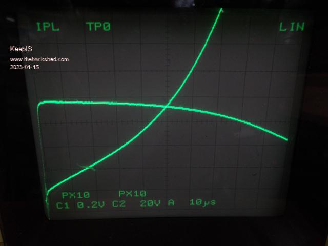
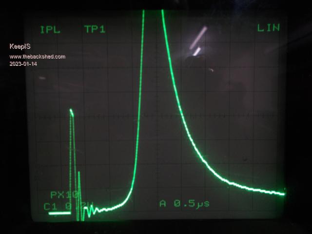
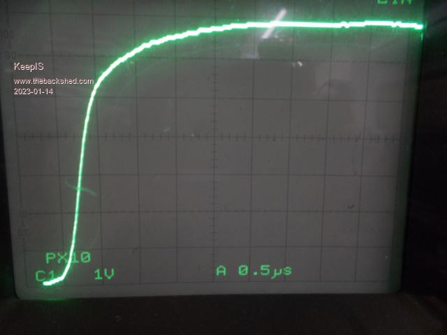
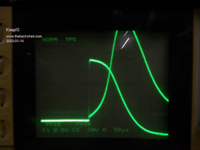
For anyone interested, these are photos of the Current through the Inductor and the voltage across the inductor, which shows the actual start point after the SCR fires.
It's very hard to see the graticule on the CRO as the Camera sees the CRO switching between the channels but it's not visible to the eye. I noticed the voltage goes negative from the collapsing magnetic field.
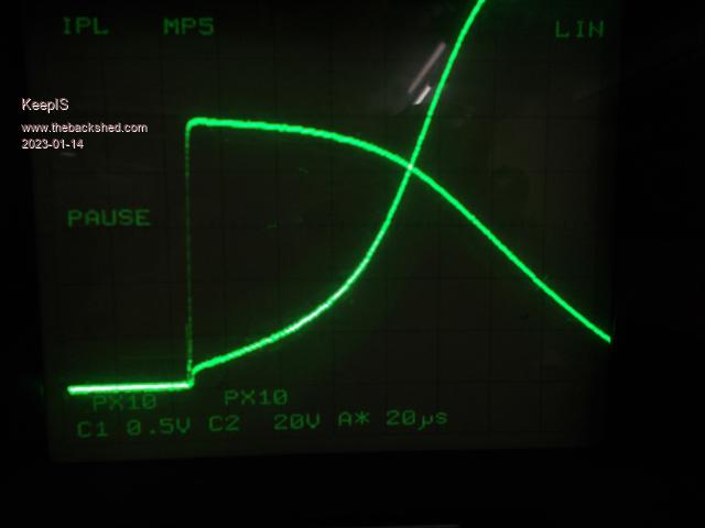
The Voltage is 100v, Current is 800A at the crossover point.
Zoomed in.
.It's all too hard. Mike.
poida Guru Joined: 02/02/2017 Location: AustraliaPosts: 1392
Posted: 11:53pm 14 Jan 2023
Copy link to clipboard
Print this post
how I do it is drive the entire transformer, with choke in circuit at the two connections (I call them V1 and V2) made at the inverter board. I disconnect one from the board to remove any effect it may have.
Today I checked it with the test inverter. The function generator is set to 3.5V p/p, 50 Ohm output. The output is connected to V1 and V2 with a 50 Ohm resistor in series. The CRO is connected to the function gen outputs, at it's BNC terminal.
This test measures the choke + transformer + cap placed on the secondary and also it includes the effect of the small 240 -> 12V feedback transformer. The whole lot.
It does resonate but the Q factor is rather small. I put the DSO in "HiRes" mode (this decimates large no.s of samples). This is to reduce the EMI my workbench is bathed in.
70 Hz 4.03 V 60 Hz 4.42 V 50 Hz 4.67 V 40 Hz 4.3 V 30 Hz 3.7 V
The peak is around 50 Hz.
The capacitor is 1.0uF The choke is 100uF. 8 1/2 turns on a double core (2 side by side) using the E70/33/32, N87 with 1mm or so gaps on the inner poles
I tried this without the choke in circuit and the peak was the same. You are right, it does not make much difference.wronger than a phone book full of wrong phone numbers
KeepIS Guru Joined: 13/10/2014 Location: AustraliaPosts: 1394
Posted: 12:53am 15 Jan 2023
Copy link to clipboard
Print this post
Thanks poida,
I spend some more time on this and I had it hooked up exactly the same way, but I went as far as shorting the inverter V1 and V2, I wanted to see if there was a higher frequency resonance hidden in there back through the choke, but happily there was almost none, just a slight peak at around 1.2 kHz.
I just retested and the resonance has shifted up by 12 Hz? I have a bigger resonance peak as well: Different transformer, physical windings, power capability I guess play a part in that? � �
FYI:
130 Hz 3.5 V 100 Hz 3.9 V 90 Hz 4 V 80 Hz 3.75 V 70 Hz 2.75 V 50 Hz 1.50 V 40 Hz 1.2 V 30 Hz 1 V �
I'm using just the 6 stack 45uH blue toriod choke, I'd need around 15kW to start saturating that, however there is a VERY slight 20 kHz (or whatever freq it is) switching ripple on the waveform, but changing loads now makes no difference to the wave shape at all, just a nice shaped sine wave, the idle is still 11 Watts, no audible noise under light loads, not even from the big Toriod, everything is just silent. So I'm getting comfortable enough now to think about powering it from a set of batteries and seeing how it goes with a bit more load. I think Edited 2023-01-15 10:54 by KeepISIt's all too hard. Mike.
KeepIS Guru Joined: 13/10/2014 Location: AustraliaPosts: 1394
Posted: 01:22am 15 Jan 2023
Copy link to clipboard
Print this post
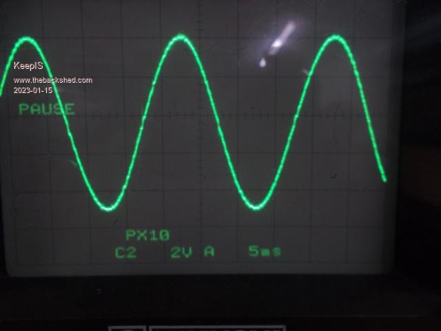
Needed an extra .47uf to bring resonance back to 75 Hz, total cap now is 1.47uF
The noise on the AC out I mentioned in previous post with 45uH choke.
It's all too hard. Mike.
poida Guru Joined: 02/02/2017 Location: AustraliaPosts: 1392
Posted: 03:19am 15 Jan 2023
Copy link to clipboard
Print this post
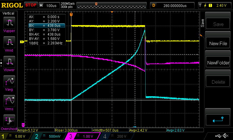
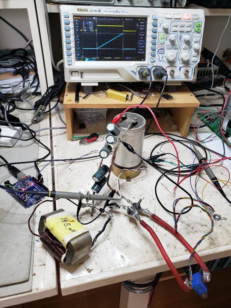
this is how I test inductors. A FET, driven by a pulse from the Arduino, width controlled by a pot. A fast diode for flyback. Any old caps in this case 5 x 4,700uF
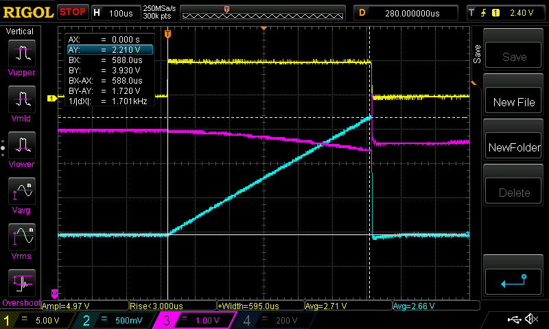
Testing the 188uF (as shown by the LCR meter) I get 13.7V average across the choke pulse width 588uS max current seen from the current sensor 40.6 A
L = V/I x time = (13.7 /40.6) * 588e-6 = 198 uH
Yellow is gate drive voltage Pink is voltage across the choke Light Blue is current
What a nice straight line! The sensor is a LEM sensor, seen bottom right in the photo. This setup is not pretty but it works for me.wronger than a phone book full of wrong phone numbers
KeepIS Guru Joined: 13/10/2014 Location: AustraliaPosts: 1394
Posted: 03:48am 15 Jan 2023
Copy link to clipboard
Print this post
Looks great, I have a bench that can look like that sometimes. Should see about coding something one day, so many thing to do and so little time � �
I was just about to post the final circuit, but now? Yes what the heck.
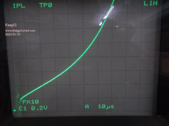
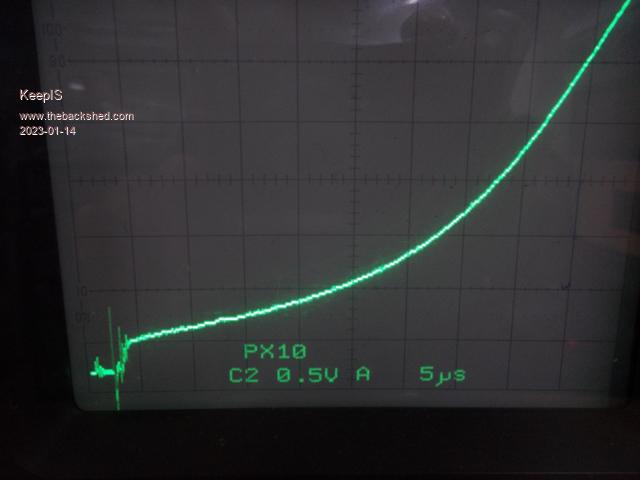
And the result: 45uH 240A choke.
Current is 80A per division, voltage and current curve. �
Just Current @ 80A per division.
. Edited 2023-01-15 13:48 by KeepISIt's all too hard. Mike.
poida Guru Joined: 02/02/2017 Location: AustraliaPosts: 1392
Posted: 03:54am 15 Jan 2023
Copy link to clipboard
Print this post
I like FETs, they can fit inside my small brain.
I just tested the double E core choke.
something like 13.5 V average 446 uS width 64 Amps at peak L = (13.5 / 64) * 446E-6 = 94uH
The LCR meter shows 100.0 at 1kHz
Saturation is clearly kicking at after 60 Amps I would use this even to 90 Amps where the effective inductance is 73 uH
The current sensor is now shunted with a 15mm2 cable to give more headroom before the sensor clips output. So the two DSO captures use different current calibrations.
I prefer to test at low voltages, it's easier to get a component to suit for my hacks. With chokes, it's a simple inverse relationship for time and voltage. Double the voltage means you have 1/2 the time available before the same current is passing through the choke.
PWM widths with the inverters we build here are of the order of 3/4 of a 20 kHz pulse, maybe 37 uS. I tested with pulse widths of 450 uS in this post Edited 2023-01-15 13:59 by poidawronger than a phone book full of wrong phone numbers
KeepIS Guru Joined: 13/10/2014 Location: AustraliaPosts: 1394
Posted: 05:10am 15 Jan 2023
Copy link to clipboard
Print this post
The software does opens up some quick interrogation of the inductor in a number of way, really like that. I'm impressed with the blue toriods though, it means (I hope) those big loads likely won't saturate the choke during their brief startup surges.
I had a couple of 200A block shunts, so it made sense to just use one on the quick made saturation tester. I also have some current sensors including the ones you use here, but I also have so called clip on current sensors, however these actually bolt together, found the better units quite stable and almost completely noise free.
I have 500A, 400A and 200A units, and a few 50A units monitoring each of the four Solar regulators. Currently 5 connected to my Solar monitor. I needed the 400A unit to Log the inverter DC input Load. It Constantly graphs in real time and saves each 20 minute segment to SD. So any glitch and I can, with a single screen touch, look at what happened at any point in time, the slightest transient is still captured.
The 400A sensor was to capture the work shed machinery startup surges of 390A, 410A and 450A for some of the bigger units. Fortunately the batteries don't even blink, even so, you can see why I'm going from 25v to 50+V.It's all too hard. Mike.
KeepIS Guru Joined: 13/10/2014 Location: AustraliaPosts: 1394
Posted: 09:50am 16 Jan 2023
Copy link to clipboard
Print this post
Looking at noise on the Inverter AC out.
I monitor the AC out via what appears to be a small current transformer? pulled from the old SMA inverters I scrapped, 600V to 7.5V 66mA VN30.15/00858 25mm square potted block, quite weighty for its size. Anyway, I use this to give me ground isolation between the CRO probe ground clip and other test gear, or when looking at more then one input on the CRO, and to help with earth loops around the inverter.
I left the gold foil shield on the AeroSharp test toriod, I wanted to see if it made any change to the common kinks in the wave form? No it didn't. Was it useful in stopping noise coupled between the primary and secondary? Yes it certainly was.
However a simple 240V filter on the secondary side of the transformer does exactly the same thing as the transformer shield. This could change at high power?
The small amount of noise reduced quite a lot, and there was no longer this weird noise induction appearing on the AC out when I touched the choke lead. I thought that was being induced into the CRO leads, but since the shield stopped that too, it's likely more just radiated noise getting into the primary windings and my test layout. �
I have found a few interesting results in this current test setup:
1: Crossover point glitches get worse as the resonating CAP value get larger.
2: Placing a CAP at the output side of the primary Choke does remove some noise, but it does the same thing as increasing the secondary CAP value, it causes the crossover glitch AND it also increased idle current, so there may be some resonance interaction at play? �
3: A lower value of resonating CAP did not increase idle current, but that may be because the lower value of CAP [1.2uF] was needed to resonate the transformer at 76 Hz.
4: The Choke from blue powdered iron mix cores at only 40uH, let a tiny amount of 24 kHz switching noise through to the secondary. However:
A: It does NOT increase idle current [11 watts], therefore it is not causing eddy current loss in the toriod, well at least not at low power loads and idle.
B: It removes most of the remaining glitches on the sine wave.
C: The sine wave no longer change shape under light loads. �
D: The transformer, choke and load are now silent at idle to 300 watts (may test limit) and zero startup noise. �
E: Using a choke with "more" inductance causes a slight startup growl and the Toriod starts to get a low frequency growl even at idle. � � This is with the transformer shield, 40uf choke and 1.2uF CAP.
I've just modded the EG002 board and I will get it connected to the batteries tomorrow. Edited 2023-01-16 20:20 by KeepISIt's all too hard. Mike.
poida Guru Joined: 02/02/2017 Location: AustraliaPosts: 1392
Posted: 09:56pm 16 Jan 2023
Copy link to clipboard
Print this post
This will be very interesting to Wiseguy. He has been on a quest to quell this growl sound.
I wrote some custom versions of the nanoverter firmware, one that made it into a variac. A pot controlled the PWM width. No feedback. Instant application of pot setting to PWM width. This was great fun to play with, exploring when saturation kicks in and how much at what voltages. I found that I could initiate the growl sounds at will using the pot with rapid increases in voltage. The faster the jump up, the louder the growl. No growl was heard when reducing voltage...wronger than a phone book full of wrong phone numbers
poida Guru Joined: 02/02/2017 Location: AustraliaPosts: 1392
Posted: 10:08pm 16 Jan 2023
Copy link to clipboard
Print this post
During most of the 20 ms period of the AC output waveform, the PWM should be seen as a train of pulses, smoothed over by the LC low pass filter. The pulses change little in width as does the output voltage when viewing a narrow part of the output in time. But crossover is different.
At crossover the PWM pulse train now should be viewed as a single very short duration pulse in a period of zero output. This pulse delivers full DC supply voltage. It's not a trivial thing to do to a resonant system at zero voltage. The toroid and other parts will be hit with this sharp pulse carrying a very wide range of frequencies and with good power too. It must ring at some frequency after the pulse hits.
This is an inherent characteristic of PWM modulating an AC sine output. Somehow near zero voltages need to be produced from very narrow PWM pulses. And at zero voltage there will be increasing gaps between the smallest available pulse widths where no pulse is required.wronger than a phone book full of wrong phone numbers
KeepIS Guru Joined: 13/10/2014 Location: AustraliaPosts: 1394
Posted: 11:08pm 16 Jan 2023
Copy link to clipboard
Print this post
Thanks for more insightful info poida.
BTW: I've also realized that I may be creating some confusion for others reading this, especially when I refer to glitches as crossover glitches, it was more to just indicate the general glitches we see moving around the "crossover points" and the associated waveform kinks that can appear up and down the sides, as seen in a lot of pictures in the various builds.It's all too hard. Mike.
Solar Mike Guru Joined: 08/02/2015 Location: New ZealandPosts: 1128
Posted: 01:02am 17 Jan 2023
Copy link to clipboard
Print this post
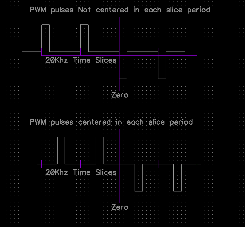
I was reading, cannot remember where, that if the PWM pulses are centered in each 20Khz time slice period, the modulation distortion is much reduced. See sketch below.
I think its much easier to produce the PWM at the start of each period, eg after timer interrupt, as in the top sketch.
If the CPU timers allow an offset and the bottom modulation achieved - 2nd sketch, then distortion products would be reduced and perhaps leading to more efficient operation.
Cheers Mike
wiseguy Guru Joined: 21/06/2018 Location: AustraliaPosts: 1009
Posted: 01:06am 17 Jan 2023
Copy link to clipboard
Print this post
It sure is, one of my last posts (30/12/22) said;
Since I wrote that I have spent zero time working on my inverter due to some other pressing projects that are currently underway. It looks like Mike has come to the same conclusion that more uH is not always better and finding the sweet spot is very worthwhile.
In one of my first posts on this subject I predicted (from calculations) a value of ~ 47uH would be my starting point with a 48V supply, but unless I misinterpreted him Warp said a higher value inductance only changes the peak to peak ripple in the choke and the actual value was not too critical.
Mike, Thanks for your ongoing investigations and detailed posts which as Poida correctly predicted has been of particular interest to me. �I have been a little jealous of not having the time presently to continue my quest to discover the right choke formula.
The blue sendust toroids I use for my chokes were originally out of a railways Sola Basic 72V to 240V inverter, that from memory used I think 36 TO220 Mosfets, 9 in each leg ! �Sendust is amazing stuff, I also thought I was doing something wrong when I tried to find their saturation point which was more like a subtle gradual curve than a knee. Keep up the good work ! Edited 2023-01-17 11:13 by wiseguyIf at first you dont succeed, I suggest you avoid sky diving.... Cheers Mike
KeepIS Guru Joined: 13/10/2014 Location: AustraliaPosts: 1394
Posted: 02:17am 17 Jan 2023
Copy link to clipboard
Print this post
Thanks for all this great in depth insight, love this forum.
Just had to try the inverter before lunch after just getting it connected to the Batteries.
I used a variac to drive a hot air gun on high, I know, only a restive load, but one step at a time.
I monitored the waveforms into the primary, the AC output and measured DC input current and AC volts. �
I was looking for any sign of saturation as I had to unwind the existing 250V secondary and use the 230v [was primary] as my test secondary. sticker said 2000VA.
However the AC out never moved from 221vac, everything appeared to be virtually silent, it was hard to tell though as the dam hot air gun was loud.
There was a slight warmth from the Toriod after a minute or so, everything else was cold, including the choke and the high side heatsink.
No good showing the AC waveform at 1600 watts as it's exactly the same from no load to 1.6kw. That was the last waveform I showed a few posts back, it just looked like it was on freeze frame. Edited 2023-01-17 12:18 by KeepISIt's all too hard. Mike.
poida Guru Joined: 02/02/2017 Location: AustraliaPosts: 1392
Posted: 02:50am 17 Jan 2023
Copy link to clipboard
Print this post
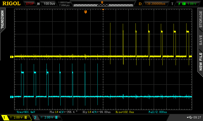
I have had yet another go at the PWM generation code for the nano/pico-verter I think I have got perfect symmetry. In the past there was a couple of small width pulses in not the right places and this probably gave rise to some part of the zero crossing wobbles.
here it is, using 10kHz PWM to make it more clear that each pulse is exactly correctly timed and going out the correct pin at the right time.
I will test this code tonight to see if it's any good.wronger than a phone book full of wrong phone numbers
wiseguy Guru Joined: 21/06/2018 Location: AustraliaPosts: 1009
Posted: 03:58am 17 Jan 2023
Copy link to clipboard
Print this post
Poida, that is the waveform I have been lusting for well done !! I do expect it to work just fine - please share what was required to actually fix it - even if the answer goes over my head I am still very interested to know. Edited 2023-01-17 13:59 by wiseguyIf at first you dont succeed, I suggest you avoid sky diving.... Cheers Mike
KeepIS Guru Joined: 13/10/2014 Location: AustraliaPosts: 1394
Posted: 04:09am 17 Jan 2023
Copy link to clipboard
Print this post
I have a few AC/DC clamp meters, one has a peak function with a with a slow decay, tried a big power saw, 140A surge, no problems. Threw a 2kw jug at it @ 41A while it boiled, 1.4kW vacuum cleaner. All just plugged into the AC out, no Variac.
No smoke yet. Going to add a quick charge start, in case I turn the Battery switch on before precharging, I'll also a Load disconnect whilst powering up, I know these are already on wiseguys boards, but I need something independent of the inverter while testing.
Because I use an ATA with the current inverter, load disconnect/connect, battery low and over voltage etc are all handled independently of the inverter anyway.
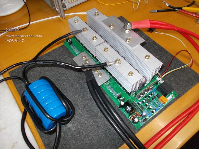
Test setup on a small part of the main battery bank rewired to 48V @ 9kW.
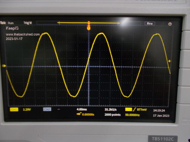
FYI: The existing HF inverter [24V -> 400VDC -> 230 AC], it's powering everything at the moment including the house and work shed, here is the mains waveform from one of the AC outlets.
. Edited 2023-01-17 14:10 by KeepISIt's all too hard. Mike.


 ).
). 

 �
�