
|
|
Forum Index : Electronics : Hopefully? Another 48vdc-240vac Toriod Inverter build.
| Author | Message | ||||
| KeepIS Guru Joined: 13/10/2014 Location: AustraliaPosts: 1405 |
I managed to get some pictures of the inverter @ 220A 12kW startup. I thought it would be a basket case, maybe it is? This is a TEST setup using an Aerosharp transformer. The 230v winding was closest to the core, I only unwound the 260v winding. I wound 27 turns of 8 AWG 7.5mm2 wire for the primary, it's going to sag. Output: set to 225Vac Input: 54 volts DC Batteries LiFePO4 : 100A all day, 300A surge 5 seconds. 53uH silicon iron Choke 8 stack toriods, 6 turns of 7.5mm2. Current: 220A then starts to saturate very slowly. Frame capture for the brief startup Surge NOTE: Under 1 second total duration. Top: Digital CRO AC waveform across the Toriod secondary terminals. Bottom: Digital storage CRO across the Toriod Primary terminals � Instant of Induction motor start, hasn't reached the Primary yet: 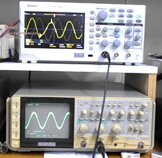 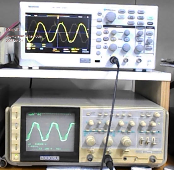 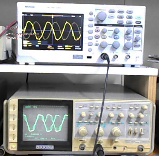 � 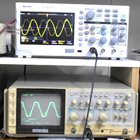 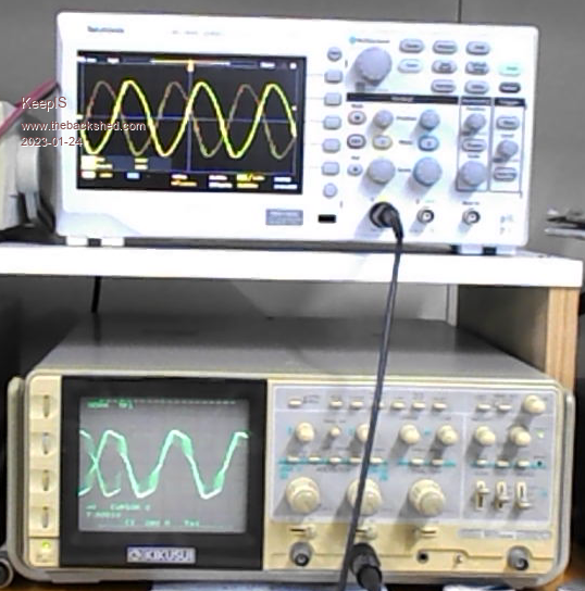 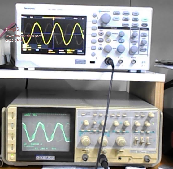 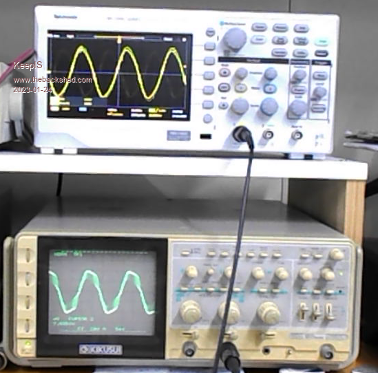 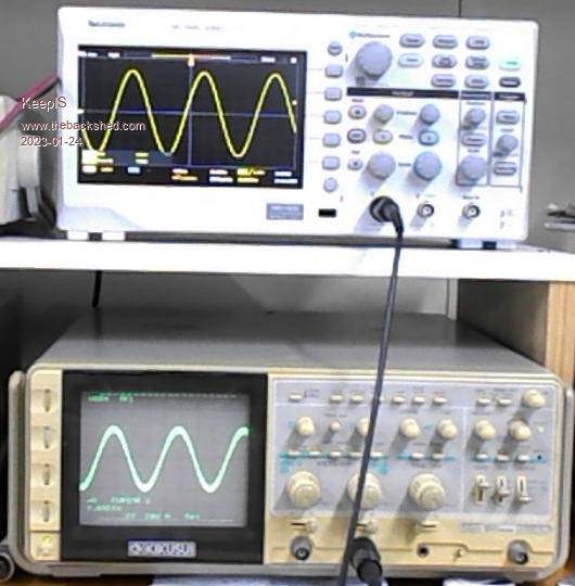 . Edited 2023-01-24 13:55 by KeepIS It's all too hard. Mike. |
||||
| wiseguy Guru Joined: 21/06/2018 Location: AustraliaPosts: 1018 |
Mike just for completeness do you have a picture of the CRO waveform with the heat-gun set to low (half-waving) you can post please? (with the filter now) I am quite intrigued to compare what it did to the waveform of about 4 pictures ago labelled "800W of crap from Low Heat gun setting" compared to now with the filter that made so much difference and when the current went from 19.5A to 17.8A? Edited 2023-01-24 14:02 by wiseguy If at first you dont succeed, I suggest you avoid sky diving.... Cheers Mike |
||||
| KeepIS Guru Joined: 13/10/2014 Location: AustraliaPosts: 1405 |
Hi Mike, actually it's down from 19.5A to 14A with the larger filter, this is the big thing that got me, I had been measuring the current a lot yesterday and today, trying different chokes, but it just proved again a bigger choke, ferite E choke etc was not as good as the 6 stack toriod, which is now around 53uH. Hi heat current always remains the same, it's just the Low heat current that has reduced in response to the different mains filters that I've tried. It's better to my eyes, inverter HI-LO drive more so, top is the other day. 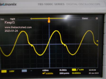 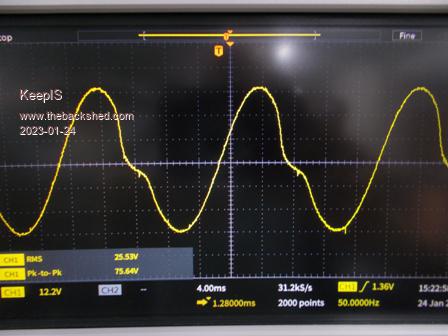   I was rushing to take picture the other day, likely because of the nasty noise, not as nasty or as loud now. . EDIT: Had the bottom two around the wrong way. Edited 2023-01-24 14:43 by KeepIS It's all too hard. Mike. |
||||
| Murphy's friend Guru Joined: 04/10/2019 Location: AustraliaPosts: 602 |
That's interesting, I have several of these filters and always thought they were used on the DC input side to the Aerosharp. Anyway, I opened one up (the coils are potted to the case), here's what's inside: 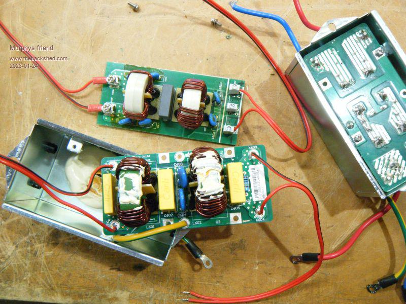 At the back is the smaller version of these chokes. The big one has 0.22uf at one side and 0.47uF the other & the middle. That side also has a 1meg resistor across it. So, as the big one uses 2.5mm sq wire coils its rated around 10A continuously. I'm looking forward to see how you end up using these filters. |
||||
| KeepIS Guru Joined: 13/10/2014 Location: AustraliaPosts: 1405 |
Thanks, I have the big unit on the right with very heavy leads, I don't have a 1M resistor though, and I changed the inside caps from .007uf to .01uf, I wanted to make 100% sure they were not surge devices. The cap are all AC rated mains caps and were close to typical values for a 240AC mains filter. I would like to know the inductance, will have to pull one toriod out and measure it, some of the bigger filters around have quite high values, I really want to investigate this further. Edited 2023-01-24 16:34 by KeepIS It's all too hard. Mike. |
||||
| wiseguy Guru Joined: 21/06/2018 Location: AustraliaPosts: 1018 |
Mike, is there any chance that switching noise is causing erroneous readings on the current meter at the half heat setting of the heat gun ? Recently I have been working on a high power DC to DC converter and when measuring currents in the circuit I was getting readings that mystified me for a while. I was measuring current with two different brands of clamp meters. I always measure the current with the clamp meter to give a positive reading for + current, but then check it the other way around to give me a negative reading. �In a perfect world the currents should be the same, however if the "zero" current point has drifted there can be a small error & in theory adding the different + & - currents and dividing by two will give the correct answer (or adjusting the zero obviously). In my circuit I was getting similar readings on both meters but vastly different readings when the meters were reversed. After a bit of head scratching I noticed that if I put my hand near the clamp jaws when taking the readings they essentially became identical, revealing that a faraday screen of sorts was affecting the noise the meter was seeing. I am afraid that I am a bit skeptical that your current really reduced that far and also given that the waveform shape does not really appear to have changed. Is it possible the addition of the Mains filtes were really filtering out some of the noise that the current meter was seeing and giving an appearance of reduced noise ? I am not saying that you used a clamp meter but I have seen similar issues with sensitive panel meters when used with shunts. I have been measuring 2kW+ DC currents from switchmode supplies for 30+ years and have seen some strange issues. I also get that you are measuring primary DC current and that the filters are on the 240V AC output but stray noise affects adjacent circuitry in strange ways sometimes. �I also suspect I won't be popular with this summary but if you have the ability to read + & - input currents it might be revealing. Lastly if it really has reduced the true current by that amount with the addition of the filter then much kudos to you for the discovery, but the reason for it and how or why it actually does that is still a mystery to me. Edited 2023-01-25 07:53 by wiseguy If at first you dont succeed, I suggest you avoid sky diving.... Cheers Mike |
||||
| KeepIS Guru Joined: 13/10/2014 Location: AustraliaPosts: 1405 |
One thing I do after working with the 24V battery system for a year with twice the current of this 50v system is to check and recheck the clamp meter readings and position. Even going to the trouble to use shunts with a the CRO across them. The current is measured in the negative leg of the battery and right at the battery terminal connection, clear of the toriods and close to a big low impedance sink, then I swap clamp meters. The two are very different in size and design, always check zero, one is manual adjust. Take out the filter and it's back up to around 19A, sounds nasty, insert filter, sound a lot better and back around 14A, single stage filter 17A. I plan on doing more tests with different mains filters to see if I get consistent variation and what works best. The thing is, the filter makes a very noticeable difference to the sound of the toriod when driving a bad load, so something is changing for the better. This is subjective, but the change in sound is like a smoothing of sharp current pulses in the transformer coming from the load. It's all too hard. Mike. |
||||
| KeepIS Guru Joined: 13/10/2014 Location: AustraliaPosts: 1405 |
Pretty much as I suspected, put an inductance in series with a sharp transient and in the simplest of terms, it's rounded. I decided to go further and place the clamp meter in the center bridge lead of 4 series connected batteries. Same change and current in both directions under any condition using the H-Gun. Putting a single 3.3mH choke in series with the one leg of the inverter AC out and the current drops by 1.3A, but Only with the H-Gun on LO causing a part rectified AC waveform, and the inductor gets warm as it pulls power out of the distorted sine wave. I put the dual stage EMI filter back in and tested my 1.4kW UPS again. I mentioned it previously as it was flattening the top of the AC waveform slightly, that has been reduced "slightly" and it now looks like the AC waveform from the HF-HV inverter I previously posted, and the toriod is once again virtually silent. It's all too hard. Mike. |
||||
| KeepIS Guru Joined: 13/10/2014 Location: AustraliaPosts: 1405 |
The devil made me do it. I had 3 SMA SunnyBoy Toriods, these were 93v to 230v windings, the 93v winding was on the core. I removed the 230v windings and found that the 93v winding was wound with a single 2.6mm diameter copper wire with around 120 turns. Thinks  3 x 93 = 279 vac, and using conservative values to keep saturation and idle current down, more likely around 260 vac winding. 3 x 93 = 279 vac, and using conservative values to keep saturation and idle current down, more likely around 260 vac winding. So, did the unthinkable and stacked the three, bit of tape around them, and ended up with 14 turn on the primary. Primary turns were set for: 230v = 27.3v 240v = 28.4 250v = 29.8 Swapped out the Aerosharp troiod, added an extra 1uf to resonate at 3 cores at 75Hz. Fired it up: No bang, 220vac out as before but increased it to 230v. Sine wave great, everything cold, idle current 18 watts. Vacuum cleaner, 124A @ 6,700 watts surge. No smoke. 230V never moved on the CRO. Heat Gun on 1.6kW perfect, on Low DOES NOT LIKE IT, more growl then aerosharp from the 3 stack transformer's but still runs it. BUT it pushes the AC output up from 230v to 239v? This primary is wound with 21mm2 and the Aerosharp test unit is wound with 7.5mm2, 26 turns on Aerosharp verses 14 turns on triple cores, although wire length is pretty close. Now to play with chokes again. Good learning experience for me to see how far I can push. I will try bigger loads once more testing is done but I'm surprised that it went as well as it did. The Advantage of series meant voltage matching is not critical (within reason), obviously I have a bit more copper loss and it's not as efficient or tight etc etc but whatever. 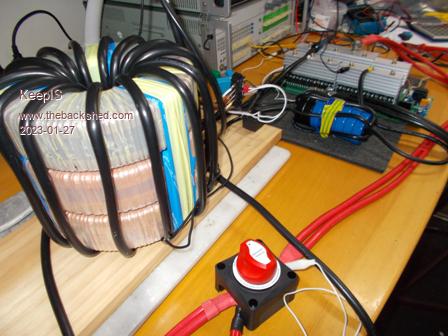 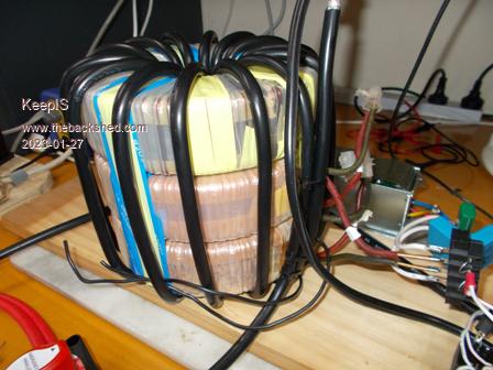 . It's all too hard. Mike. |
||||
| KeepIS Guru Joined: 13/10/2014 Location: AustraliaPosts: 1405 |
Re-terminated some of the connections I had made for the test of the 3 toriods. I placed the 53uH 240A Silicon Iron toriod choke in the LO side to the transformer and a DOUBLE E71 Ferrite E-Core choke with 1.5mm gap and 31uH @ 160A in the HI side connection. As I have someone here to start the band saw and the big Grinder, I was able to watch the various waveforms and hold the kill switch, Wow! The Vacuum cleaner was first, didn't record that as it basically does nothing to the 3 stack toriod and inverter. The Heat Gun, the problem of the AC going up on the Low power distorted waveform is gone, and surprisingly, the chokes don't get warm like they did with the Aerosharp. I can only assume that this is because this 3 stack Transformer is not saturating. � The Grinder: 52A - 2.7kW on start for a good second. Wave forms were just nice sine waves with small ripples. Transformers barely made any noise. Chokes had a slight smooth sounding Hum that sort of matches the small ripples in the sine wave, the sine wave is measured across the primary of the transformer. The Band Saw, Instant kick start (identical to mains 240v start) but that startup actually takes all of 2 seconds as it spins up the Heavy flywheels and 1/2" blade. Band Saw startup - 255A @ 49V = 12.5kW The waveforms did not show any clipping, just slanted slightly and small ripples, AC out did not budge and that was at the full 12.5kW 225A spike. Transformer just a light hum, the chokes make more hum, but it was all very civilized and smooth sounding, just like the waveforms look �  Once the Band saw and Grinder had spun up, of course everything was silent. Idle power: 19.2 watts. � 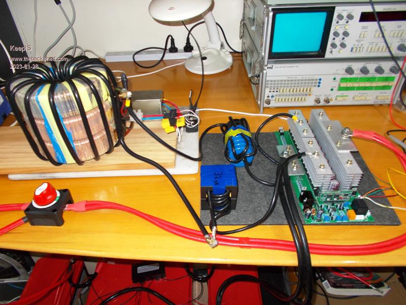 The tiny black transformer sitting between the chokes and the Toriod provides ground isolation of the CRO probe when displaying AC waveform from the Toriod. 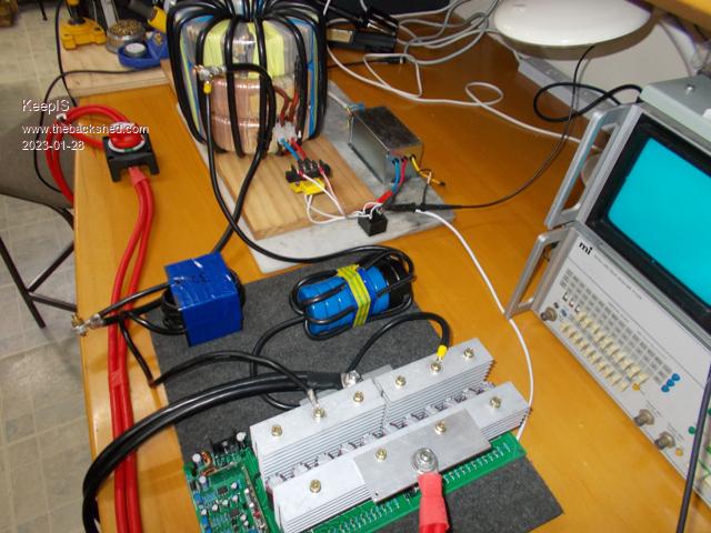 . Edited 2023-01-29 07:47 by KeepIS It's all too hard. Mike. |
||||
| KeepIS Guru Joined: 13/10/2014 Location: AustraliaPosts: 1405 |
This wins the prize for being the first inverter to start our 3HP dust extractor. It's not the highest current draw at 248A and 12.4kW, but it's the hardest to start because of the long long startup time holding that current for almost 5 seconds as the huge impeller slowly spins up, the 230V AC dropped down to 210V but still maintained the same tilted sine wave with no ringing, flat top or spikes. FYI the startup time and sound are the same when powering with mains AC. � � The Air Compressor has the highest draw, 282A and 14.1kW on startup, but it's a quicker 1.5 second start. Started like on mains. The Band saw, 250A and 12.5kW started up like on mains - no AC voltage sag. � The cable on the Silicon toriod ring Choke got warm starting the Dust extractor. It's wound with 6mm solar cable as it's a test unit, I wanted to test an inductance of 53uH, so that was the only cable that would give me the number of turns. The double Ferrite E-core cable only slightly warm as it's wound with heaver cable. The Toriod transformer obviously still dead cold including the primary winding. A slight warmth to the High Side heat sink only. � These 3 devices were started one after the other, with the air compressor twice. . Edited 2023-01-29 10:43 by KeepIS It's all too hard. Mike. |
||||
| mab1 Senior Member Joined: 10/02/2015 Location: United KingdomPosts: 175 |
Thanks for posting all this - as it happens i too bought a '24v' inverter board like yours, the only difference is that it actually says 12-72v input on the pcb. The idea was to have it as a stand-in in case the powerjack went belly up (it's still going fine). But as my existing 24v lead acid battery is probably close to end of life i was considering building this inverter to 48v and making the leap to a 48v system when i replace the battery. Out of curiosity, are you planning on stripping your triple stack tranny back and rewinding with all the cores together? or are you leaving it as is? Edited 2023-01-29 10:41 by mab1 |
||||
| KeepIS Guru Joined: 13/10/2014 Location: AustraliaPosts: 1405 |
That depends on how it goes running our normal loads with respect to heat. At the moment I'm not really up to winding a big toriod. The toriod choke is dropping quite a few volts, I knew that would be the case, but now that I have the dual E-cores @ 31uH and not saturating until well over 120A, I can lower the toriod choke back to around 28uH wound with heavy wire. This 3 stack transformer loves both chokes, the E-Core in the HI side and the toriod choke in the low side. The Aerosharp test toriod only liked one, and only in the HI side, and it worked best with the toriod choke. BTW these wide input inverter boards put out a lot of EMI from the 12-74V to 12v DC-DC switching supply, so trying to filter the AC output will not filter that radiation interference. Something to look at later if it's a problem, although this will only be used as a backup driver board, if it survives �  EDIT: I accurately measured the idle power with this Transformer with both an inline meter and precision power supply, it's just 18.7 Watts. I never thought I could get a big inverter to get even close to the 24 Watts idle power of a small Night time inverter that I switch over to from the Main HF-DC inverter. The Main inverter is rated at 5kW / 10kW peak and it idles at around 60 to 80 watts. I don't need that going all night with minimal loads. This test inverter does the job of both, only better. When I get the chokes rewound to suite the new Transformer I'll do some efficiency tests, but a quick preliminary test at a few hundred watts, indicates that it can't be done at low power with clamp meters. The only real difference I could see between DC input power and AC output power was the idle current, and that can't be right, so I need to get the efficiency tests setup correctly. . Edited 2023-01-29 15:28 by KeepIS It's all too hard. Mike. |
||||
| Murphy's friend Guru Joined: 04/10/2019 Location: AustraliaPosts: 602 |
And you win the prize for doing all that of a 24V battery. You really must like big fat cables and gigantic connecting lugs  . .I would never even consider running such loads of a 24V inverter  (I started with a 24V system, BTW, but quickly changed to 48V once I tried running my house from it). (I started with a 24V system, BTW, but quickly changed to 48V once I tried running my house from it). With those 3 stacked toroid transformers, using their original windings for the secondary, I would suspect there is a fair bit of unwanted magnetic coupling between those original windings. You might get an even better idle power if you re wind it as a single 3 stack core. If that original wire can be re used it requires only the effort of doing it as straightening that size wire is not easy. But I have done it when re cycling the wire from Aerosharp chokes, so its doable  . . |
||||
| KeepIS Guru Joined: 13/10/2014 Location: AustraliaPosts: 1405 |
HI, yes I was running these loads off a 24V system, but with a Transformer-less inverter, I'm still using that until I complete this new build and change over to a 48V system. This test inverter is running off of 53v, so at least I'm not drawing over 480A to run the same loads at 24V. And yes, attention to detail and understanding High currents (relative to a home inverter systems) helps. There is no magnetic coupling that I can measure, I have a single primary, if I drive 90vac into one of the transformer secondaries, there is ZERO voltage on the other two secondaries. One of the things about toriods is they appear to contain their magnetic field and since there is no shared Core material they don't appear to inductively couple in close proximity. I had a feeling this would be the case but had to try it to see, and 18 watts idle at 230v is pretty dam good. I had it running for a few hours today with only a few hundred watts and the transformer was stone cold, no eddy current loss apparent. I'm limited because the solar panels are wired for a 24V system and this is still in use with the old inverter. I'm running on 4 of the system batteries connected up for 55v with no way to charge them (well the most I can charge at is 4A @ 54v), so I can't do a full day typical load test to see how it goes. However, I just found my small 20 year old 100A CIG arc welder, it has a transformer with a two position primary selection and gives 40vac and 47vac on the secondary, and nothing stupid in the transformer core setup, it almost looks like a square toriod of sorts, so a charger should be forthcoming quickly and then I can run extended testing and recharge in a reasonable time. I'm limited to how much effort or force I can use at the moment as I recover from two heart attacks, so a rewind will have to wait. Apology for long reply. . It's all too hard. Mike. |
||||
Revlac Guru Joined: 31/12/2016 Location: AustraliaPosts: 964 |
Yes that's quite high idle losses, the 5048MS inverter on the house is 50W, most of that comes out as heat from the choke and some from the IGBT's, at least with the DIY inverters we can make a good choke that Doesn't get that hot and waste power all the time. Sounds familiar.....All wound on one side? Cheers Aaron Off The Grid |
||||
| noneyabussiness Guru Joined: 31/07/2017 Location: AustraliaPosts: 506 |
dc welder or this idea for a charger... tough and cheap.. I think it works !! |
||||
| KeepIS Guru Joined: 13/10/2014 Location: AustraliaPosts: 1405 |
Aluminum strap winding on the LH side and 240V spool winding on the Top side of the square, so the two windings form an L shape in the core. Yes 18 Watts idle on this test inverter is so much nicer. Thanks for the link, I saw oztules original post from around 2018 a few months back, but they had trouble with the newer units from memory. Might look into that again if this unit gets to heavy to move around. Edited 2023-01-30 07:54 by KeepIS It's all too hard. Mike. |
||||
| wiseguy Guru Joined: 21/06/2018 Location: AustraliaPosts: 1018 |
Love the progress you have made with the 24V inverter. The DC current figures are just mind boggling (& a bit scary). I have to say I'm a bit in awe of the rapid progress you have been making in such a relatively short time including choke experiments. I suspect that 3 core toroid with its 3 primary windings in series for the mains output is a great solution with minimal winding to boot. Adding a few more turns and rejigging the choke and it should be fine for 48V usage too. I suspect you wont even bother doing a total re-winding of the cores & keep it as it currently stands ? If at first you dont succeed, I suggest you avoid sky diving.... Cheers Mike |
||||
| KeepIS Guru Joined: 13/10/2014 Location: AustraliaPosts: 1405 |
Thanks Mike. Just one thing that's getting missed in all the posts, my fault I guess: The inverter board I was given was initially a 24V board, however I quickly converted that 24V board over to 48V input. So a recap 1: This complete build / test has been with an Inverter running at a nominal 55V. 2: The scary currents are all measured between 48.6V to 56V Inverter DC input. BTW: Currents under 285 Amps seem fine to me now after living with a 24V Transformer-less inverter nudging 500 Amps for some loads at startup  The way I feel at the moment I'll just use the 3 stack as it is. I really want to start putting together your version of the Inverter. Thanks again for all the help and for the future help I may need with getting your inverter design up and running . It's all too hard. Mike. |
||||
