
|
|
Forum Index : Microcontroller and PC projects : Picomite(VGA) V5.07.07 betas - bug fixes + focus on PIO
| Author | Message | ||||
disco4now Guru Joined: 18/12/2014 Location: AustraliaPosts: 844 |
On Beta 6 the example from page 2 doesn't seem the work properly if it is ask to transfer more that 32 words/items?. This outputs to the LEDs as expected. PIO DMA_OUT 1,2,32,packed%(),dmadone,16,32 Anything where nbr is >32 seems to not wrap to the start of the packed%() as expected and LEDs are not as expected after the first two cycles e.g. PIO DMA_OUT 1,2,64,packed%(),dmadone,16,32 PIO DMA_OUT 1,2,&H100,packed%(),dmadone,16,32 PIO DMA_OUT 1,2,&H1000,packed%(),dmadone,16,32 Also a documentation question? 'PIO DMA_OUT pio, sm, nbr, data%() [,completioninterrupt] [,transfersize] [,loopbackcount] nbr specifies how many 32-bit words to transfer (as in the Readme.txt) nbr specifies how many data items are to be read or written (should it be this?) Latest F4 Latest H7 |
||||
| phil99 Guru Joined: 11/02/2018 Location: AustraliaPosts: 1813 |
Also the last version of the 3 phase program for Beta 6 on page 3 crashes VGA beta 6.1 and self erases. Saved 2593 bytes > RUN press any key to trigger yes Error: Invalid address - resetting PicoMiteVGA MMBasic Version 5.07.07b6 Copyright 2011-2023 Geoff Graham Copyright 2016-2023 Peter Mather > LIST > > option list PicoMiteVGA MMBasic Version 5.07.07b6 OPTION COLOURCODE ON OPTION KEYBOARD US OPTION DISPLAY 60, 106 OPTION SDCARD GP13, GP10, GP11, GP12 OPTION COUNT GP6,GP7,GP14,GP15 OPTION DEFAULT FONT 7, 1 > Re-loaded program from TBS same result, re-flashed b6.1 same result. Copied this version from non-VGA Pico and it works. Trivial changes to PWM section that should have no effect. ' Test signal: Three phase motor drive - picomite V50706+ ' runs autonomously on GP0...GP5 50Hz SetPin gp0,pwm 'CH 0a SetPin gp1,pwm 'CH 0b SetPin gp2,pwm 'CH 1a SetPin gp3,pwm 'CH 1b SetPin gp4,pwm 'CH 2a SetPin gp5,pwm 'CH 2b Fpwm = 50 PW = 100 / 3 PWM 0, Fpwm, PW, PW - 100, 1, 1 PWM 1, Fpwm, PW, PW - 100, 1, 1 PWM 2, Fpwm, PW, PW - 100, 1, 1 PWM sync 0, 100/3, 200/3 Pause 20 '----------------------------------- LA code PIO -------------------------- 'PIO code to sample GP0..GP6 for logic analyzer PIO clear 1 'in this program the PIO reads GP0..GP5 brute force 'and pushes data into FIFO. The clock speed determines the 'sampling rate. There are 2 instructions per cycle 'taking 10000/2 / 50 = 100 samples per cycle. 'the PIO program 'address code mnemonics comment ' 0 2016 WAIT GP22=0 wait for trigger to become low ' 1 2096 WAIT GP22=1 wait for trigger to become high '.wrap target ' 2 4006 IN pins 6 read 6 pins ' 3 8020 PUSH block and push '.wrap 'program pio1 PIO program line 1,0,&h2016 PIO program line 1,1,&h2096 PIO program line 1,2,&h4006 PIO program line 1,3,&h8020 'configuration f=1e4 'PIO run at 10kHz p=Pio(pinctrl 0,0,0,gp0,,,) 'IN base = GP0 e=Pio(execctrl gp22,2,3) 'wrap 3 to 2, gp22 is conditional JMP pin s=Pio(shiftctrl 0,0,0,0,0,0) 'shift in through LSB, out is not used 'write the configuration, running 10kHz (data in FIFO 10us after rising edge GP0) PIO init machine 1,0,f,p,e,s,0 'start address = 0 '---------------------------- LA code MMBasic ---------------------------------- 'prepare trigger signal set to idle SetPin gp22,dout Pin(gp22)=0 Font 7 'do not start PIO, the DMA will do that. Dim a$(1)=("_","-") length%=64 Dim data%(2*length%-1) 'array to put the 32 bit samples Dim packed%(length%-1) 'DMA array to pack 32 bit samples in 64 bit integers ' PIO DMA_IN 1,0,2*length%,packed%(),ReadyInt 'let the machine run, and wait for trigger Do PIO DMA_IN 1,0,2*length%,packed%(),ReadyInt Print "press any key to trigger" Do :Loop While Inkey$="" Print "yes" Pulse gp22,1 Pause 200 Loop End '-----------------------------------SUBS MMBasic -------------------------------- Sub ReadyInt PIO stop 1,0 Memory unpack Peek(varaddr packed%()),Peek(varaddr data%()),2*length%,32 For j=0 To 5 mask%=2^j For i=0 To 2*length%-1 If i<106 Then Print a$(((data%(i) And mask%)=mask%)); Next i Print : Print ' : Print Next j 'PIO DMA_IN OFF End Sub Edited 2023-01-20 15:27 by phil99 |
||||
| Pluto Guru Joined: 09/06/2017 Location: FinlandPosts: 330 |
This corrected the MEMORY UNPACK issue (as you probably have tested and noticed yourself already).  |
||||
| Volhout Guru Joined: 05/03/2018 Location: NetherlandsPosts: 3589 |
Hi Peter, I have a few questions regarding the DMA. Not that it does not work, but I am not sure how to set it up correctly. 1/ Create ring buffer Anything smaller than 256 does not seem to work (32, 64, 256) despite being a power of 2 2/ PIO DMA_IN pio, sm, nbr, data%() [,completioninterrupt] [,transfersize] [,loopbackcount] When you use a ring buffer, do you need to feed it with "nbr" ? 3/ PIO DMA_IN pio, sm, nbr, data%() [,completioninterrupt] [,transfersize] [,loopbackcount] When you use a ring buffer, does it ever reach "completioninterrupt" ? I hope I get this right 'The DMA should take (2*length 32 bit) samples, this takes up (1*length 64 bit) ring buffer 'It should never trigger the ReadyInt interrupt (ringbuffer). Not sure if we need specify 'the number of samples. PIO DMA_IN 1,0,2*length%,packed%(),ReadyInt,32,length% 'start DMA with ring buffer I tried loopback parameter: length 2*length 4*length 8*length (number of bytes the DMA buffer is in size) ERROR: Data alignment error length-1 2*length-1 4*length-1 8*length-1 (number of bytes the DMA buffer is in size) ERROR: not a power of 2 I have no clue what to do next... Volhout ' Test signal: Three phase motor drive - picomite V50706+ ' runs autonomously on GP0...GP5 50Hz SetPin gp0,pwm 'CH 0a SetPin gp1,pwm 'CH 0b SetPin gp2,pwm 'CH 1a SetPin gp3,pwm 'CH 1b SetPin gp4,pwm 'CH 2a SetPin gp5,pwm 'CH 2b PWM 0, 50, 33.33, -66.66, 1, 1 PWM 1, 50, 33.33, -66.66, 1, 1 PWM 2, 50, 33.33, -66.66, 1, 1 PWM sync 0, 100/3, 200/3 Pause 20 '----------------------------------- LA code PIO -------------------------- 'PIO code to sample GP0..GP6 for logic analyzer PIO clear 1 'in this program the PIO reads GP0..GP5 brute force 'and pushes data into FIFO. The clock speed determines the 'sampling rate. There are 3 instructions per cycle 'taking 10000/3 / 50 = 66 samples per cycle. 'the PIO program 'address code mnemonics comment '.wrap target ' 0 80A0 pull block 'pull data from FIFO into OSR when available ' 1 A027 mov(x,osr) 'load gate time (in clock pulses) from osr ' 2 4006 IN pins 6 'read 6 pins ' 3 8000 PUSH noblock 'and push to FIFO ' 4 00C2 JMP (GP22) 2 'while no trigger (GP22=1) loop to 2 ' 5 4006 IN pins 6 'read 6 pins ' 6 8000 PUSH noblock 'and push to FIFO ' 7 0045 JMP (X<>0) 5 X-- 'while X<>0 decrement X and jump to 5 '.wrap 'program pio1 PIO program line 1,0,&h80A0 PIO program line 1,1,&hA027 PIO program line 1,2,&h4006 PIO program line 1,3,&h8000 PIO program line 1,4,&h00C2 PIO program line 1,5,&h4006 PIO program line 1,6,&h8000 PIO program line 1,7,&h0045 'configuration f=1e4 'PIO run at 10kHz p=Pio(pinctrl 0,0,0,gp0,,,) 'IN base = GP0 e=Pio(execctrl gp22,0,7) 'wrap 7 to 0, gp22 is conditional JMP pin s=Pio(shiftctrl 0,0,0,0,0,0) 'shift in through LSB, out is not used 'write the configuration, running 10kHz PIO init machine 1,0,f,p,e,s,0 'start address = 0 '---------------------------- LA code MMBasic ---------------------------------- 'prepare trigger signal set to idle (above PIO code needs falling edge trigger) SetPin gp22,dout Pin(gp22)=1 'do not start PIO, the DMA will do that. 'reserve data buffers length%=256 Dim data%(2*length%-1) 'array to put the 32 bit samples 'Dim packed%(length%-1) 'DMA array to pack 32 bit samples in 64 bit integers Dim packed% 'name of the array to be formed as circular array PIO MAKE RING BUFFER packed%,length% 'this creates array called "packed%()" 'dim variables Dim a$(1)=("_","-") Dim done%=0 'below code must be adapted for circular FIFO buffer........................!!!! Do Print "press <SPACE> to arm LA" Do : Loop Until Inkey$=" " 'The DMA should take (2*length 32 bit) samples, this takes up (1*length 64 bit) ring buffer 'It should never trigger the ReadyInt interrupt (ringbuffer). Not sure if we need specify 'the number of samples. 'PIO DMA_IN 1,0,2*length%,packed%(),ReadyInt,32,length% 'start DMA with ring buffer PIO DMA_IN 1,0,2*length%,packed%(),ReadyInt,,4*length%-1 'start DMA with ring buffer 'write to PIO the number of post trigger samples, this starts the logging of pre-trigger data PIO WRITE 1,0,1,length% Pause 200 Print "press "t" to trigger LA" Do : Loop Until Inkey$="t" 'the trigger pulse, must be wider that 3 / f(pio) in seconds. 'for 10kHz, that is 0.3ms Pulse gp22,1 'pulse 1ms 'from here the PIO should autocomplete and wait for another post trigger length% written 'wait a bit (can calculate from post trigger length and sampling speed), default for now Pause 200 'stop DMA, stop PIO, re-config PIO PIO DMA_IN OFF PIO STOP 1,0 PIO init machine 1,0,f,p,e,s,0 'start address = 0 'process the data from the ring buffer Memory unpack packed%(),data%(),2*length%,32 For j=0 To 5 mask%=2^j For i=0 To 2*length%-1 Print a$(((data%(i) And mask%)=mask%)); Next i Next j Math set 0,packed%() Loop End '-----------------------------------SUBS MMBasic -------------------------------- Sub ReadyInt Print "we should not get here ------------- *****" PIO DMA_IN OFF End Sub PicomiteVGA PETSCII ROBOTS |
||||
| matherp Guru Joined: 11/12/2012 Location: United KingdomPosts: 8604 |
Therefore you can just use a normal array for anything less than or equal to 256 bytes. The size of the ring buffer is in bytes so you adjust this to your transfer size (1,2,or 4 bytes) and the number of transfers in the loop (loopbackcount) Yes, the RP2040 doesn't have a loop-forever capability so nbr needs to be specified. You can use &HFFFFFFFF Yes: when nbr runs out 'dma_out continuous ' demo program to demonstrate the use of the PIO interrupt ' the PIO is programmed to pull 1 word from FIFO at every rising edge of the GP pin. ' the LSB 5 bits are shown on GP1..GP5 (diagnostics) ' the GP0 pin is controlled from MMBasic in this demo, but could also be driven from ' an external source. '-------------------------------- PIO state machine ----------------------------------- 'PIO clear, and attach pins to PIO 1 PIO clear 1 SetPin gp1,pio1 SetPin gp2,pio1 SetPin gp3,pio1 SetPin gp4,pio1 SetPin gp5,pio1 Dim integer unpacked%(127),packed% npackedadd=Peek(varaddr unpacked%()) For i=0 To 31 unpacked%(i)=i unpacked%(63-i)=i unpacked%(64+i)=i unpacked%(127-i)=i Next PIO make ring buffer packed%,512 Memory pack unpacked%(),packed%(),128,32 'the PIO program 'address � �code � �mnemonics � � � � � � comment ' �0 � � �E09F � � �SET pindirs &b11111 � GP1..GP5 out ' �1 � � �2000 � � �WAIT GP0=0 � � � � � �wait for external trigger on GP0 to pull ' �2 � � �2080 � � �WAIT GP0=1 ' �3 � � �8080 � � �PULL noblock � � � � �pulls data off fifo ' �4 � � �6005 � � �OUT OSR > pins 5 � � �shift 5 bits to GP1..5 pins ' �5 � � �0001 � � �JMP 1 � � � � � � � � repeat PIO program line 1,0,&hE09F PIO program line 1,1,&h2000 PIO program line 1,2,&h2080 PIO program line 1,3,&h8080 PIO program line 1,4,&h6005 PIO program line 1,5,&h0001 'write the configuration, running 1MHz f=1e6 p=Pio(pinctrl 0,5,5,gp0,,gp1,gp1) � �'pins GP1...GP5 = out, GP0 = in ' �s=PIO(shiftctrl 0,0,0,0,1,1) � � � �'default value ' �e=PIO(execctrl gp0,0,31) � � � � � �'default value: wrap defaults, GP0 = cond JMP pin ' �PIO init machine 1,0,f,p,e,s,0 � � �'PIO 1 SM 0 start adress = 0 PIO init machine 1,2,f,p,,,0 � � � � 'PIO 1 SM 0 start adress = 0 '-------------------------------- MMBasic MAIN --------------------------------------- 'Halt the PIO from GP0 from MMBasic before it fills the FIFO out of control SetPin gp0,dout Pin(gp0)=0 'variables Dim d%=0 'start the pio1 code, state machine 1.0 will be waiting for a rising edge on the GP0 pin 'then it will pull 1 word from fifo. Then it will wait for the falling edge. The cycle repeats. 'set the dma to loop over 32 16-bit shorts for a very long time PIO DMA_OUT 1,2,&H10000,packed%(),dmadone,32,128 'freguently PIO pull data from the fifo SetTick 200,PullFifo 'Main: interrupt free loop polling the NOT TX_FULL flag in FSTAT Do If a% Then �SetTick 0,0 �End EndIf Loop End '----------------------------------- SUBS --------------------------------------- 'in this sub we toggle the GP0 pin to force the PIO to fetch data from the FIFO Sub PullFifo Pulse gp0,10 End Sub Sub dmadone Print "All done" a%=1 End Sub Edited 2023-01-20 18:46 by matherp |
||||
| Volhout Guru Joined: 05/03/2018 Location: NetherlandsPosts: 3589 |
@Peter Thanks for educating. Tha basis works now. But I notice that when you force stop the DMA, you trigger DMA_Ready interrupt. I can work around that. Also the "nbr" is a signed integer (&hFFFFFFFF does not work, it needs to be &h7FFFFFFF). Volhout Edited 2023-01-20 19:26 by Volhout PicomiteVGA PETSCII ROBOTS |
||||
| matherp Guru Joined: 11/12/2012 Location: United KingdomPosts: 8604 |
If you don't want the interrupt don't include it in the command PIO DMA_OUT 1,2,&H10000,packed%(),,32,128 |
||||
| Volhout Guru Joined: 05/03/2018 Location: NetherlandsPosts: 3589 |
Getting there, need to re-align trigger to the centre. All excited !!! Trigger is parallel wired to channel 15. 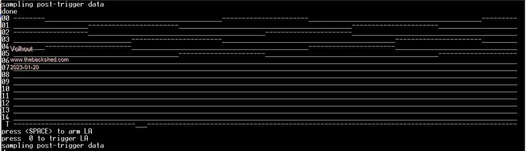 Edited 2023-01-20 19:37 by Volhout PicomiteVGA PETSCII ROBOTS |
||||
| Pluto Guru Joined: 09/06/2017 Location: FinlandPosts: 330 |
From Peter's program above: For i=0 To 31 unpacked%(i)=i unpacked%(63-i)=i unpacked%(64+i)=i unpacked%(127-i)=i Next PIO make ring buffer packed%,512 Memory pack unpacked%(),packed%(),128,32 When I run the program and look at the outputs on the LEDS (GP1 to GP5): Sub PullFifo Pulse gp0,10 inc count Leds=pin(gp1)+(pin(GP2)<<1)+(pin(gp3)<<2)+(pin(gp4)<<3)+(pin(gp5)<<4) print count;" &h";HEX$(count)," GP1:5:";Leds End Sub Running the program all seems to be OK in the beginning, but after 128 PullFifo the output on the leds become strange (in my mind): 113 &h71 GP1:5: 15 114 &h72 GP1:5: 14 115 &h73 GP1:5: 13 116 &h74 GP1:5: 12 117 &h75 GP1:5: 11 118 &h76 GP1:5: 10 119 &h77 GP1:5: 9 120 &h78 GP1:5: 8 121 &h79 GP1:5: 7 122 &h7A GP1:5: 6 123 &h7B GP1:5: 5 124 &h7C GP1:5: 4 125 &h7D GP1:5: 3 126 &h7E GP1:5: 2 127 &h7F GP1:5: 1 128 &h80 GP1:5: 0 129 &h81 GP1:5: 0 Extra zeroes starting from here. 130 &h82 GP1:5: 0 131 &h83 GP1:5: 1 132 &h84 GP1:5: 0 133 &h85 GP1:5: 2 134 &h86 GP1:5: 0 135 &h87 GP1:5: 3 136 &h88 GP1:5: 0 137 &h89 GP1:5: 4 138 &h8A GP1:5: 0 139 &h8B GP1:5: 5 140 &h8C GP1:5: 0 141 &h8D GP1:5: 6 142 &h8E GP1:5: 0 After a while nothing is output anymore. It is quite possible that I have misunderstood the Ringbuffer, but to me it looks suspicious. |
||||
| Volhout Guru Joined: 05/03/2018 Location: NetherlandsPosts: 3589 |
Just to give you something to play with, no questions anymore. The core works. From here is is elbow grease to make it into a logic analyzer. ToDo: - Decide on trigger logic - Make pan and scan work - Nice VGA graphics (the first will be a 6 channel fast LA) maybe later a 32 channel slower one, with different trigger logic. Requires external HW. Here is the working core. 'logic analyzer framework research program 'samples GP0...GP15 with triggering on GP22 on standard picomite 'uses PIO and ring buffer under DMA. 'requires Picomite MMBasic V50707b6 or newer. 'Volhout 20-1-2023 ' Test signal: Three phase motor drive - picomite V50706+ ' runs autonomously on GP0...GP5 50Hz SetPin gp0,pwm 'CH 0a SetPin gp1,pwm 'CH 0b SetPin gp2,pwm 'CH 1a SetPin gp3,pwm 'CH 1b SetPin gp4,pwm 'CH 2a SetPin gp5,pwm 'CH 2b PWM 0, 50, 33.33, -66.66, 1, 1 PWM 1, 50, 33.33, -66.66, 1, 1 PWM 2, 50, 33.33, -66.66, 1, 1 PWM sync 0, 100/3, 200/3 Pause 20 '----------------------------------- LA code PIO -------------------------- 'PIO code to sample GP0..GP15 for logic analyzer PIO clear 1 'in this program the PIO reads GP0..GP5 brute force 'and pushes data into FIFO. The clock speed determines the 'sampling rate. There are 3 instructions per cycle 'taking 10000/3 / 50 = 66 samples per cycle. 'the PIO program 'address code mnemonics comment '.wrap target ' 0 80A0 pull block 'pull data from FIFO into OSR when available ' 1 A027 mov(x,osr) 'load gate time (in clock pulses) from osr ' 2 4010 IN pins 16 'read 16 pins ' 3 8000 PUSH noblock 'and push to FIFO ' 4 00C2 JMP (GP22) 2 'while no trigger (GP22=1) loop to 2 ' 5 4010 IN pins 16 'read 16 pins ' 6 8000 PUSH noblock 'and push to FIFO ' 7 0045 JMP (X<>0) 5 X-- 'while X<>0 decrement X and jump to 5 '.wrap 'program pio1 PIO program line 1,0,&h80A0 PIO program line 1,1,&hA027 PIO program line 1,2,&h4010 PIO program line 1,3,&h8000 PIO program line 1,4,&h00C2 PIO program line 1,5,&h4010 PIO program line 1,6,&h8000 PIO program line 1,7,&h0045 'configuration f=1e4 'PIO run at 10kHz p=Pio(pinctrl 0,0,0,gp0,,,) 'IN base = GP0 e=Pio(execctrl gp22,0,7) 'wrap 7 to 0, gp22 is conditional JMP pin s=Pio(shiftctrl 0,0,0,0,0,0) 'shift in through LSB, out is not used 'write the configuration, running 10kHz PIO init machine 1,0,f,p,e,s,0 'start address = 0 '---------------------------- LA code MMBasic ---------------------------------- 'prepare trigger signal set to idle (above PIO code needs falling edge trigger) SetPin gp22,dout Pin(gp22)=1 'do not start PIO, the DMA will do that. 'reserve data buffers 'The logic analyzer captures 2*length% (32 bit max) samples. 'These are stored in array "data%()" using 2*length% integers (64 bit variables) 'The DMA buffer has 64bit width, is packed with 32bit FIFO (2 per cell) = length% 'The size of the ring buffer is specified in bytes, so size is 8*length% length%=256 Dim data%(2*length%-1) 'array to put the 32 bit samples (in option base 0) 'Dim packed%(length%-1) 'DMA array to pack 32 bit samples in 64 bit integers Dim packed% 'name of the array to be formed as circular array PIO MAKE RING BUFFER packed%,8*length% 'this creates array called "packed%()" 'dim display characters Dim a$(1)=("_","-") '---------------------------------------- MAIN ----------------------------------------- Do Print "press <SPACE> to arm LA" Do : Loop Until Inkey$=" " 'The DMA should take 2*length samples (= loopback value) 'It should never trigger the ReadyInt interrupt (ringbuffer) hence we make the number of 'samples near infinite (&hFFFFFFFF). When we force stop the DMA then ReadyInt will trigger. 'the number of samples. PIO DMA_IN 1,0,&h7FFFFFFF,packed%(),ReadyInt,32,2*length% 'start DMA with ring buffer 'write to PIO the number of post trigger samples, this starts the logging of pre-trigger data PIO WRITE 1,0,1,length% Pause 200 Print "press 't' to trigger LA" Do : Loop Until Inkey$="t" 'the trigger pulse, must be wider that 3 / f(pio) in seconds. 'for 10kHz, that is 0.3ms Pulse gp22,1 'pulse 1ms (1->0->1) 'from here the PIO should autocomplete and wait for another post trigger length% written Print "sampling post-trigger data" 'wait a bit (can calculate from post trigger length and sampling speed), default for now Pause 200 'stop DMA, this will call ReadyInt that stops the PIO and re-init it. PIO DMA_IN OFF 'process the data from the ring buffer Memory unpack packed%(),data%(),2*length%,32 'calculate position of the trigger point in the ring buffer endpoint%=Pio(DMA RX POINTER)-Peek(VARADDR packed%()) 'value in bytes endpoint%=endpoint% / 4 'convert to 32 bit values for use in data%() trigger%=(endpoint%-length%) 'recalculate trigger from end capture If trigger%<0 Then trigger%=trigger%+2*length% 'look at wrap around 'Print trigger% 'calculate view window based on screen size (width = 128 chars) start%=trigger%-64 stop%=trigger%+63 'output to serial port screen For j=0 To 15 'check 15 bits GP0..GP15 mask%=2^j 'mask GPx If j=15 Then 'assume GP15 also wired trigger Print " T "; Else Print Right$("0"+Str$(j),2)+" "; 'channel number EndIf 'now we select 3 cases depending on start and stop. This must be optimized later 'case 1: view window inside array boundaries 'case 2: start% outside array boundaries 'case 3: staop% outside array boundaries 'case 2 If start%<0 Then For i=start%+2*length% To 2*length%-1 Print a$(((data%(i) And mask%)=mask%)); Next i For i=0 To stop% Print a$(((data%(i) And mask%)=mask%)); Next i 'case 3 ElseIf stop%>2*length%-1 Then For i=start% To 2*length%-1 Print a$(((data%(i) And mask%)=mask%)); Next i For i=0 To stop%-2*length% Print a$(((data%(i) And mask%)=mask%)); Next i 'case 1 Else For i=start% To stop% Print a$(((data%(i) And mask%)=mask%)); Next i EndIf Next j 'clear array (maybe not needed) Math set 0,packed%() Loop End '-----------------------------------SUBS MMBasic -------------------------------- 'stops and re-initializes the PIO to be ready for next DMA Sub ReadyInt PIO STOP 1,0 PIO init machine 1,0,f,p,e,s,0 'start address = 0 Print "done" End Sub P.S. Peter. Is it better to standardize on RX and TX and not mix with IN and OUT ? Or do you have a reason to use these names ? Standardize on IN and OUT is another option. PicomiteVGA PETSCII ROBOTS |
||||
| matherp Guru Joined: 11/12/2012 Location: United KingdomPosts: 8604 |
You mean change DMA_IN and DMA_OUT to DMA_RX and DMA_TX? If so, yes on the next beta |
||||
| Volhout Guru Joined: 05/03/2018 Location: NetherlandsPosts: 3589 |
Sorry I was not clear: yes that was what I suggested. Either use RX and TX everywhere, or use IN and OUT everywhere. That will make the user manual more clear, and make it more intuitive. Thanks for your continued support !! PicomiteVGA PETSCII ROBOTS |
||||
| matherp Guru Joined: 11/12/2012 Location: United KingdomPosts: 8604 |
NB: to all B6 has introduced an error in DMA_OUT loopback which is now ignored. I've found the problem code which is a call to the SDK which should have no affect but does. I'll post b7 with the fix when I've done a bit more investigation Edited 2023-01-21 00:04 by matherp |
||||
| matherp Guru Joined: 11/12/2012 Location: United KingdomPosts: 8604 |
PicoMite(VGA)V5.07.07b7 https://geoffg.net/Downloads/picomite/PicoMite_Beta.zip Fixed bug in DMA loopback for output. Fixed formatting bug in GUI output of floats Command name changes: DMA RX was DMA_IN DMA TX was DMA_OUT |
||||
| Volhout Guru Joined: 05/03/2018 Location: NetherlandsPosts: 3589 |
Hi Peter, I hope you can help me. Attached ZIP has 2 programs. LA_4.bas and LA_5.bas. The program LA_4.bas is the logic analyzer that works as I expect. If you type "t" repeated, it shows the sampled data from the 15 input ports of a picomite. Using V50707b7 If you connect GP22 to GP15 you also see the trigger. Then program LA_5.bas This program shows corrupted data in the last 128 samples of the data%() array (alternating correct value, next sample 0). Only the last 128 samples. If you change the value of "samples%" from 512 to 256, or 1024, the last 128 samples show this behaviour (the numerics show the start pointer, mid pointer, and stop pointer of the displayed values). You may have to type "t" a few times. When start%<0 or stop%>samples%-128 it is visible, commented out is a section that displays the data that is in the packed%() array. And also the packed%() array shows this artefact. The last 64 values seem corrupted. And I have no idea what is going wrong. The PIO code is the same, the DMA configuration is the same. The levels of the signals on my breadboard are correct. I have looked for hours, and cannot find what is going wrong. Have stripped LA_5.bas back to almost identical to LA_4.bas. I have no idea. I hope you can spot what is going wrong. Volhout LA.zip 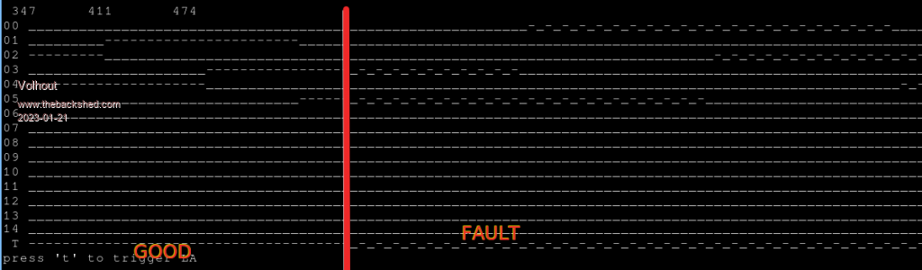 Edited 2023-01-21 08:09 by Volhout PicomiteVGA PETSCII ROBOTS |
||||
| phil99 Guru Joined: 11/02/2018 Location: AustraliaPosts: 1813 |
Playing with LA4.bas found an odd thing with PWM Sync. It doesn't start PWM channel 4 and stops it if it was already running. Here is what was added to LA4.bas 'logic analyzer framework research program 'samples GP0...GP15 with triggering on GP22 'uses PIO and �ring buffer under DMA. 'requires V50707b7 or newer (function names changed) ' Test signal: Three phase motor drive - picomite V50706+ ' runs autonomously on GP0...GP5 50Hz SetPin gp0,pwm �'CH 0a SetPin gp1,pwm �'CH 0b SetPin gp2,pwm �'CH 1a SetPin gp3,pwm �'CH 1b SetPin gp4,pwm �'CH 2a SetPin gp5,pwm �'CH 2b SetPin gp6,pwm �'CH 3a SetPin gp7,pwm �'CH 3b SetPin gp8,pwm �'CH 4a SetPin gp9,pwm �'CH 4b SetPin gp10,pwm �'CH 5a SetPin gp11,pwm �'CH 5b Fpwm = 50 PW = 100 / 6 PWM 0, Fpwm, PW, PW - 100, 1, 1 PWM 1, Fpwm, PW, PW - 100, 1, 1 PWM 2, Fpwm, PW, PW - 100, 1, 1 PWM 3, Fpwm, PW, PW - 100, 1, 1 PWM 4, Fpwm, PW, PW - 100, 1, 1 PWM 5, Fpwm, PW, PW - 100, 1, 1 PWM sync 0, 100/6, 200/6, 300/6, 400/6, 500/6 Pause 20 '----------------------------------- LA code PIO -------------------------- This is the output 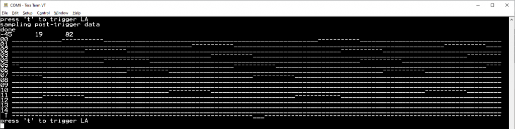 Having already been caught by a faulty GP0 (needs a pulldown resistor). I have tested GP8 & 9 to verify that they function properly with DOUT, DIN and PWM. This also occurs at the command line, not just in the program, which shows exactly what I see on the scope. Edit The pin numbers for PWM7 seem to be cross linked to other pins. PicoMite MMBasic Version 5.07.07b7 Copyright 2011-2023 Geoff Graham Copyright 2016-2023 Peter Mather > pwm 6, off > pwm 7, off > setpin gp15,pwm > setpin gp14,pwm Error : Already Set to pin 20 > setpin gp13,pwm Error : Already Set to pin 20 > setpin gp12,pwm > setpin 20, off > setpin 19, off > setpin 17, off > setpin gp14,pwm > setpin gp15,pwm Error : Already Set to pin 19 > Found when using this:- Fpwm = 50 PW = 100 / 8 For n%=0 To 15 'Set the PWM pins GP0 to GP15 �PINn = MM.Info(pinno "GP"+Str$(n%)):Print "GP";n%,"Pin";PINn �SetPin PINn, PWM �If n% And 1 Then PWM n%\2, Fpwm, PW, PW - 100, 1, 1 Next PWM sync 0, 100/8, 200/8, 300/8, 400/8, 500/8, 600/8, 700/8 Pause 20 '----------------------------------- LA code PIO -------------------------- It works up to PWM6 but not PWM7 - GP14 & GP15. . Edited 2023-01-21 14:14 by phil99 |
||||
| Volhout Guru Joined: 05/03/2018 Location: NetherlandsPosts: 3589 |
Peter, Thonking about the artefact in LA_5 Looks like from a certain location in the circular buffer the dma is writing fifo data(32-to-64), in stead of packing it(32+32-to-64). Maybe the location where the buffer is in Ram is the cause. Or the packed array and data array overlap, the memory unpack overwrites part of the packed array. Volhout Edited 2023-01-21 17:52 by Volhout PicomiteVGA PETSCII ROBOTS |
||||
| Volhout Guru Joined: 05/03/2018 Location: NetherlandsPosts: 3589 |
@phill, Do you have an option set for system i2c. That may reserve gp pins. Volhout PicomiteVGA PETSCII ROBOTS |
||||
| Pluto Guru Joined: 09/06/2017 Location: FinlandPosts: 330 |
Volhout, the location where the problems start is &h81 . |
||||
| matherp Guru Joined: 11/12/2012 Location: United KingdomPosts: 8604 |
Phil Thanks for the report, cut and paste typo "enabled=16" should have been "enabled|=16" Will be fixed in next beta. Now to look at Volhout's issue - might be harder  |
||||
