
|
|
Forum Index : Microcontroller and PC projects : Picomite(VGA) V5.07.07 betas - bug fixes + focus on PIO
| Author | Message | ||||
| matherp Guru Joined: 11/12/2012 Location: United KingdomPosts: 10180 |
PicoMite(VGA)V5.07.07b8 https://geoffg.net/Downloads/picomite/PicoMite_Beta.zip Fixes bug in PWM SYNC for channel 4 Fixes bug in PIO MAKE RING BUFFER that allowed it to overlap arrays defined before it Volhout - this should fix your issue |
||||
| phil99 Guru Joined: 11/02/2018 Location: AustraliaPosts: 2579 |
Thanks for the prompt fix of Sync for PWM_4. There also appears to be a cross connection between the pins for PWM_6 and PWM_7. Saved 6675 bytes GP 0 PIN 1 GP 1 PIN 2 GP 2 PIN 4 GP 3 PIN 5 GP 4 PIN 6 GP 5 PIN 7 GP 6 PIN 9 GP 7 PIN 10 GP 8 PIN 11 GP 9 PIN 12 GP 10 PIN 14 GP 11 PIN 15 GP 12 PIN 16 GP 13 PIN 17 GP 14 PIN 19 [17] SetPin PINn, PWM Error : Already Set to pin 17 > > option list PicoMite MMBasic Version 5.07.07b8 OPTION FLASH SIZE 16777216 OPTION CPUSPEED (KHz) 378000 OPTION DISPLAY 60, 132 > > LIST 'logic analyzer framework research program 'samples GP0...GP15 with triggering on GP22 'uses PIO and ring buffer under DMA. 'requires V50707b7 or newer (function names changed) ' Test signal: Three phase motor drive - picomite V50706+ ' runs autonomously on GP0...GP5 50Hz Phases = 8 Fpwm = 50 PW = 100 / Phases For n%=0 To Phases * 2 - 1 PINn = MM.Info(pinno "GP"+Str$(n%)) : Print "GP";n%,"PIN "PINn SetPin PINn, PWM If n% And 1 Then PWM n% \ 2, Fpwm, PW, PW - 100, 1, 1 Next ' *************** insert a "'" after the last phase in the next line *********************** PWM sync 0, 100/ Phases, 200/ Phases, 300/ Phases, 400/ Phases, 500/ Phases, 600/ Phases, 700/ Phases Pause 20 '----------------------------------- LA code PIO -------------------------- This happens at the command line too. If PWM_7 is setup first PWM_6 says it's pins are already in use. |
||||
| ville56 Senior Member Joined: 08/06/2022 Location: AustriaPosts: 220 |
Besides, PicoMite(VGA)V5.07.07b8 also solves the issue with floating point handling in the gui numberbox. ctrlval() now returns the value in the expected precision. Thanks for the solution !! Regards, Gerald 73 de OE1HGA, Gerald |
||||
| matherp Guru Joined: 11/12/2012 Location: United KingdomPosts: 10180 |
Please download b8 again if required I've now fixed the issue with SETPIN 19,PWM and SETPIN 20,PWM. This was a real bizarre C language one. Pin functions are defined by a 64-bit bitmap #define SPI1RX � � (1 << 15) #define SPI1TX � � (1 << 16) #define SPI1SCK � � (1 << 17) #define PWM0A � � (1 << 18) #define PWM0B � � (1 << 19) #define PWM1A � � (1 << 20) so I can check if a pin can do a particular function by looking in a table { 17, 13, "GP13", �DIGITAL_IN | DIGITAL_OUT | UART0RX | I2C0SCL | PWM6B ,99, 134}, � � // pin 17 PWM6B was defined as (1 << 31) - so should be &H80000000 but was actually giving &HFFFFFFFF80000000 as it was treated as a signed value even though it was being assigned to a 64-bit unsigned data item. Now PWM7A was defined as &H100000000 and PWM7B as &H200000000 so when I tested for matches by anding the two 64 bit words together all three 6B, 7A, and 7B all matched PWM6B NB: SETPIN 19,PWM7A and SETPIN 20,PWM7B both work as expected  Edited 2023-01-21 23:29 by matherp |
||||
| Volhout Guru Joined: 05/03/2018 Location: NetherlandsPosts: 5021 |
Peter, It works, thanks! Volhout PicomiteVGA PETSCII ROBOTS |
||||
| phil99 Guru Joined: 11/02/2018 Location: AustraliaPosts: 2579 |
Yes it does. Thankyou. 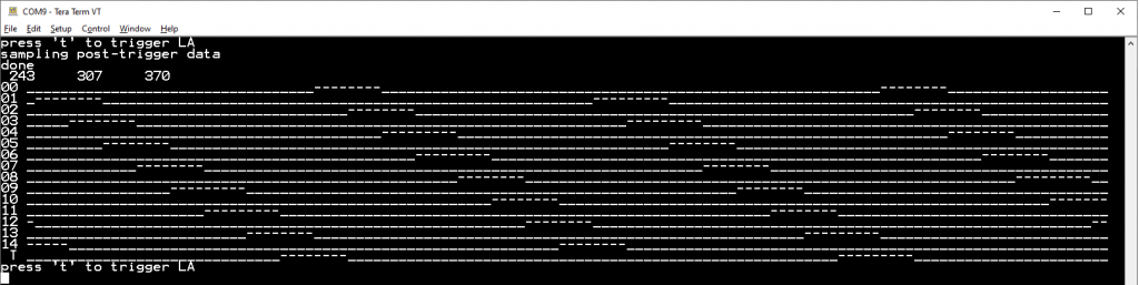 |
||||
| matherp Guru Joined: 11/12/2012 Location: United KingdomPosts: 10180 |
V5.07.07b10 https://geoffg.net/Downloads/picomite/PicoMite_Beta.zip Change in timing for touch with SSD1963 displays to improve stability New command PIO assemble pio,linedata$ This command will assemble and load text based PIO assembler code including labels for jumps Use: PIO assemble pio,".program anything" to initialise the assembler Use: PIO assemble pio,".side_set n [opt] [pindirs]" if using side set. This is mandatory in order to correctly construct the op-codes if one or more side set pins are used. It does not load the pinctrl register as this is specific to the state-machine. Also note the "opt" parameter changes the op-code for instructions that have a side parameter Use: PIO assemble pio,".line n" to assemble starting from a line other than 0 - this is optional Use: PIO assemble pio,".end program [list]" to terminate the assembly and program the pio. The optional parameter LIST causes a hex dump of the op-codes to the terminal. Use: PIO assemble pio,"label:" to define a label. This must appear as a separate command. Use: PIO assemble pio "instruction [parameters]" to define the actual PIO instructions that will be converted to machine code The assembler is tested against various of the Pico PIO examples but there is a lot of cut-and-paste so please report any errors. AFAIK it is completely comprehensive. Source code if anyone is interested PIOassembler.zip e.g. PIO assemble 1,".program myprog" 'start the assembly PIO assemble 1,".line 0" PIO assemble 1,".side_set 1 opt pindirs" PIO assemble 1,"do_nack:" PIO assemble 1,"jmp y-- �12" PIO assemble 1,"irq wait 0 rel" PIO assemble 1,"do_byte:" PIO assemble 1,"set x,7" PIO assemble 1,"bitloop:" PIO assemble 1,"out pindirs,1 [7]" PIO assemble 1,"nop side 1 [2]" PIO assemble 1,"wait 1 pin,1 [4]" PIO assemble 1,"in pins,1 [7]" PIO assemble 1,"jmp x-- bitloop side 0 [7]" PIO assemble 1,"out pindirs, 1 [7]" PIO assemble 1,"nop side 1 [7]" PIO assemble 1,"wait 1 pin, 1 [7]" PIO assemble 1,"jmp pin do_nack side 0 [2]" PIO assemble 1,"entry_point:" PIO assemble 1,"out x,6" PIO assemble 1,"out y,1" PIO assemble 1,"jmp !x do_byte" PIO assemble 1,"out null,32" PIO assemble 1,"do_exec:" PIO assemble 1,"out exec,16" PIO assemble 1,"jmp x-- do_exec" PIO assemble 1,".end program list" Edited 2023-01-25 05:12 by matherp |
||||
| Volhout Guru Joined: 05/03/2018 Location: NetherlandsPosts: 5021 |
Wauw Peter, You make me re-think the way I write PIO code. So now we have 3 ways to write PIO code: MMBasic embedded, MMedit+MMreplace, and hand assembly. For now I just want to share the status of the logic analyzer, which is done the old manual assembly way. The trigger is build in for the VGA picomite. There are 6 input channels (may become 8 later, but then you loose audio), and you can trigger on any logical combination of the 6 channels. The user interface is still terminal. For trigger you can choose "x" (don't care), "1" and "0". Type that in a string for the 6 channels. i.e. 100001 means trigger when GP0=1, GP1=0, GP2=0, GP3=0, GP4=0, GP5=1 i.e. 1xxxxx means trigger when GP0=1 With the build in test signal some combinations will wait forever (i.e. 11xxxx) since this does not occur. Next : add edge trigger Next : add GUI (thanks Martin, will use yours) The current trigger triggers guaranteed when the trigger condition is stable for 300ns. This is caused by the way the trigger works (it requires 20 PIO cycles maximum). 'problem: trigger always fires 2x in MMCC, not in putty � '+----------------------------------------------------+ '| � � logic analyzer framework research program � � �| '| � � � � � � � � � � � � � � � � � � � � � � � � � �| '| Volhout � � � � � � � � � � � � � � � � 20-1-2023 �| '+----------------------------------------------------+ 'samples GP0...GP15 with triggering on GP22 'uses PIO and ring buffer under DMA. 'requires V50707b8 or newer (function names changed) � '---------------------- version control ---------------- ' LA_3 �uses DMA after manual trigger, serial output ' LA_4 �uses DMA and ring buffer, serial output ' LA_5 �testbed to debug DMA ' LA_6 �restructure (this version) tbd PIO is ready ' LA_7 �unroll circular buffer to linear array ' LA_8 �triggering works � '-------------- �prepare and init the picomite for LA --------------- � �generate_test_signal � � � � � � � �'--debug-- test signal �PIO_prog � � � � � � � � � � � � � �'program the PIO to sample � �samples% = 512 � � � � � � � � � � �'must be 2^x, larger than 256 �init_memory � � � � � � � � � � � � 'set up data buffers �init_trigger_config � � � � � � � � 'set up choice arrays � �setup_screen � � � � � � � � � � � �'set default screen parameters � �single=0 � � � � � � � � � � � � � �'mode of operation (single shot) � � '------------------------------ main loop ------------------------------- � 'the new UI must be the type of � 'do ' � read keyboard ' � if "a" then arm DMA PIO ' � if "<" then move centre, display ' � if ">" then move centre, display ' � if "^" then zoom in, display ' � if "V" then zoom out, display ' � if "t" then unarm, trigger setup ' � if "s" then unarm, sample setup ' � if PIO ready then update, display 'loop � 'the old linear user interface �Do � �If single=1 Then � � �Print "press <SPACE> to arm LA" � � �Do : Loop Until Inkey$=" " � �EndIf � � 'loop delay to get better view of data ' � �pause 2000 � � 'decode trigger � �input"input trigger string (x/1/0) 6 characters for GP0..5 -or- <CR> to keep:", z$ � �if len(z$)=6 then � � �setup_trigger_pattern � �end if � � 'start la, wait for trigger � �arm_la � � 'calculate minimal circular buffer prefill time � �filltime%=int(1000*3*length% / f0)+1 � �pause filltime% � � 'fill pre-trigger buffer � � 'enable_trigger � �enable_trigger � � � � 'wait for trigger to happen � �do � �loop while pin(gp22)=1 � � 'from here the PIO should autocomplete and wait for another post trigger length% written 'wait a bit (can calculate from post trigger length and sampling speed), default for now � �pause filltime% � �'fill post-trigger buffer � � 'stop DMA, this will call ReadyInt that stops the PIO and re-init it. � �PIO DMA RX OFF � � � � � � � � � � � � � � �'also unpacks the data � � 'display the data � �linprint �Loop � End � � � � '-----------------------------------SUBS MMBasic -------------------------------- � 'convert the trigger string to PIO instructions for state machine 1 'program these instructions into pre-defined locations sub setup_trigger_pattern �for h%=1 to 6 � �for g%=0 to 2 � � �if mid$(z$,h%,1)=c$(g%) then � � � �PIO program line 1,11+3*h%,p%(g%) � � 'program locations 14,17,....29 � � � �print 11+3*h%,"&h";hex$(p%(g%)) � � �end if � �next g% �next h% � � end sub � 'start the trigger engine sub enable_trigger �PIO start 1,1 end sub � 'trigger characters related to PIO instructions sub init_trigger_config �dim c$(2)=("x","1","0") �dim p%(2)=(&hE020,&h002A,&h004A) end sub � 'temporary serial screen setup Sub setup_screen '------------------------screen setup ------------------------------- 'display window information �screenwidth=128 � 'characters �viewwidth = 128 � 'samples �viewpoint = 0.5 � 'mid screen = default trigger position �magnify = 1 � � � 'zoom level � 'adapt terminal screen to required resolution �Option display 40,screenwidth+4 � 'display characters for waveform LOW,HIGH �Dim a$(1)=("_","-") End Sub � � 'unpack packed%() to unpacked%() such that trigger is in the centre (linear time) Sub unroll �varindex%=(Pio(DMA RX POINTER)-Peek(VARADDR packed%()))/8 � � � 'value in bytes->64 �beginsamples% = 2*(varindex%) �endsamples% = samples% - beginsamples% �Memory unpack Peek(varaddr packed%(varindex%)),unpacked%(),endsamples%,32 �Memory unpack packed%(), Peek(varaddr unpacked%(endsamples%)),beginsamples%,32 'Print samples%,length%,endpoint%,varindex%,beginsamples%,endsamples% End Sub � 'print the traces on the serial output Sub linprint 'print section st% to sp% of the linear array to serial (screen) �st%=samples%/2-64: sp%=samples%/2+63 �Print Space$(2+64);"T" �For j%=0 To 5 � �mask%=2^j% � �Print Right$(" "+Str$(j%),2)+" "; � �For i%=st% To sp% � � �Print a$(((unpacked%(i%) And mask%)=mask%)); � �Next i% �Next j% �print : print : print End Sub � 'when DMA is ready stop PIO's and re-init for next DMA, then unroll buffer Sub ReadyInt ' �PIO STOP 1,0 �PIO stop 1,1 �PIO init machine 1,1,f1,p1,e1,s1,10 � 'start address = 10 (0x0A) �PIO init machine 1,0,f0,p0,e0,s0,0 � � 'start address = 0 �unroll �math set 0,packed%() End Sub � � 'Start the DMA to accept FIFO data from PIO 1.0, and set the posttrigger value Sub arm_la 'the DMA will time out after &h7FFFFFFF samples, or when stopped �PIO DMA RX 1,0,&h7FFFFFFF,packed%(),ReadyInt,32,samples% � � �'start DMA with ring buffer � 'write to PIO the number of post trigger samples, starts the logging of pre-trigger data �PIO WRITE 1,0,1,posttrigger% � End Sub � Sub init_memory '----------------------- define data buffers ------------------------------- 'The logic analyzer captures samples% samples into the packed%() array' 'The DMA buffer has 64bit width, is packed with 32bit FIFO (2 per cell) = length% 'The size of the ring buffer is specified in bytes, so size is 8 * length% 'the samples will be unpacked into unpacked%() at 32 bits per location (=2*lenth%) � �posttrigger% = samples% / 2 � � � �'set trigger in centre of circular buffer data �length% = samples% / 2 � � � � � � 'packed buffer = 64bit, data buffer staores 32 bit (in 64 bit vars) � �Dim data%(samples%-1) � � � � � � �'array to put the 32 bit samples (in option base 0) � �Dim unpacked%(samples%-1) � � � � �'array to put the 32 bit samples (in option base 0) debug debug debug � �Dim packed% � � � � � � � � � � � �'name of the array to be formed as circular array 64 bit wide 'PIO MAKE RING BUFFER creates array called "packed%()" specified in bytes (64 bits = 8*) �PIO MAKE RING BUFFER packed%,8*length% � End Sub � � Sub generate_test_signal ' Test signal: Three phase motor drive - picomite V50706+ ' runs autonomously on GP0...GP5 50Hz � �SetPin gp0,pwm �'CH 0a �SetPin gp1,pwm �'CH 0b �SetPin gp2,pwm �'CH 1a �SetPin gp3,pwm �'CH 1b �SetPin gp4,pwm �'CH 2a �SetPin gp5,pwm �'CH 2b � �PWM 0, 50, 33.33, -66.66, 1, 1 �PWM 1, 50, 33.33, -66.66, 1, 1 �PWM 2, 50, 33.33, -66.66, 1, 1 � �PWM sync 0, 100/3, 200/3 �Pause 20 End Sub � � 'program the PIO with the sampler code (PIO 1.0) and the trigger 'framework (PIO 1.1) that is reprogrammed each time trigger is changed Sub PIO_prog � 'assign GP22 (trigger_not) to PIO �setpin gp22,pio1 � 'the PIO 1.0 program: the sampler 'in this program the PIO reads GP0..GP5 brute force 'and pushes data into FIFO. The clock speed determines the 'sampling rate. There are 3 instructions per cycle � 'address � �code � �mnemonics � � � � comment ' �0 � � � �E081 � �SET GP22 output '.wrap target ' �1 � � � �E001 � �SET GP22 high ' �2 � � � �80A0 � �pull block � � � �'pull data from FIFO into OSR when available ' �3 � � � �A027 � �mov(x,osr) � � � �'load gate time (in clock pulses) from osr � ' �4 � � � �4006 � �IN pins 6 � � � � 'read 6 pins ' �5 � � � �8000 � �PUSH noblock � � �'and push to FIFO ' �6 � � � �00C4 � �JMP (GP22) 4 � � �'while no trigger (GP22=1) loop to 4 � ' �7 � � � �4006 � �IN pins 6 � � � � 'read 6 pins ' �8 � � � �8000 � �PUSH noblock � � �'and push to FIFO ' �9 � � � �0047 � �JMP (X<>0) 7 X-- �'while X<>0 decrement X and jump to 7 '.wrap � 'clean start �PIO clear 1 � 'program pio1.0 : sampler �PIO program line 1,0,&hE081 � �PIO program line 1,1,&hE001 �PIO program line 1,2,&h80A0 �PIO program line 1,3,&hA027 � �PIO program line 1,4,&h4006 �PIO program line 1,5,&h8000 �PIO program line 1,6,&h00C4 � �PIO program line 1,7,&h4006 �PIO program line 1,8,&h8000 �PIO program line 1,9,&h0047 � � � 'program pio 1.1 : trigger engine 'since PIO does not know logic, we shift in bits, and qualify each bit at a time 'this makes PIO trigger slow (21 instructions), so 300ns (f1=63MHz) is needed 'for guaranteed trigger detection � 'address � �code � �mnemonics � � � � comment '.wrap target ' �10 � � � 4006 � �IN ISR 6 � � � � �shift in the same data as the sampler ' �11 � � � A0E6 � �MOV ISR->OSR � � �mov data to shift out register � ' �12 � � � E020 � �clear X � � � � � clear X register, prepare for new bit ' �13 � � � 6021 � �OUT OSR->X 1 � � �shif 1 bit (GP0) into X register ' �14 � � � E020 � �dummy � � � � � � will be re-programmed with conditional jump on X � ' �15 � � � E020 � �clear X � � � � � clear X register, prepare for new bit ' �16 � � � 6021 � �OUT OSR->X 1 � � �shif 1 bit (GP1) into X register ' �17 � � � E020 � �dummy � � � � � � will be re-programmed with conditional jump on X � 'etc... � ' �27 � � � E020 � �clear X � � � � � clear X register, prepare for new bit ' �28 � � � 6021 � �OUT OSR->X 1 � � �shif 1 bit (GP5) into X register ' �29 � � � E020 � �dummy � � � � � � will be re-programmed with conditional jump on X � ' �30 � � � E000 � �SET GP22 low � � �we passed all qualifiers -> trigger = OK '.wrap ' �31 � � � 000A � �JMP wrap targer � not needed... � � 'program pio 1.1 : trigger engine �PIO program line 1,10,&h4006 �'IN ISR 6 �PIO program line 1,11,&hA0E6 �'MOV ISR->OSR � �PIO program line 1,12,&hE020 �'clr X �PIO program line 1,13,&h6021 �'OUT OSR->X 1 �PIO program line 1,14,&hE020 �'trigger GP0 � �PIO program line 1,15,&hE020 �'clr X �PIO program line 1,16,&h6021 �'OUT OSR->X 1 �PIO program line 1,17,&hE020 �'trigger GP1 � �PIO program line 1,18,&hE020 �'clr X �PIO program line 1,19,&h6021 �'OUT OSR->X 1 �PIO program line 1,20,&hE020 �'trigger GP2 � �PIO program line 1,21,&hE020 �'clr X �PIO program line 1,22,&h6021 �'OUT OSR->X 1 �PIO program line 1,23,&hE020 �'trigger GP3 � �PIO program line 1,24,&hE020 �'clr X �PIO program line 1,25,&h6021 �'OUT OSR->X 1 �PIO program line 1,26,&hE020 �'trigger GP4 � �PIO program line 1,27,&hE020 �'clr X �PIO program line 1,28,&h6021 �'OUT OSR->X 1 �PIO program line 1,29,&hE020 �'trigger GP5 � �PIO program line 1,30,&hE000 �'set GP22 low �PIO program line 1,31,&h000A �'jmp top � � 'configuration PIO 1.0 �f0=1e4 � � � � � � � � � � � � � � 'PIO run at 10kHz �p0=Pio(pinctrl 0,1,0,gp0,,GP22,) � � � 'IN base = GP0, SET = GP22 �e0=Pio(execctrl gp22,1,9) � � � � �'wrap 9 to 1, gp22 is conditional JMP pin �s0=Pio(shiftctrl 0,0,0,0,0,1) � � �'shift in through LSB, out is not used � 'configuration PIO 1.1 �f1=63e6 � � � � � � � � � � � � � �'PIO run at 63MHz �p1=Pio(pinctrl 0,1,0,gp0,,GP22,) � 'IN base = GP0, SET = GP22 �e1=Pio(execctrl gp0,10,30) � � � � �'default �s1=Pio(shiftctrl 0,0,0,0,0,1) � � �'shift in through LSB, out through LSB � 'write the configurations �PIO init machine 1,0,f0,p0,e0,s0,0 � �'start address = 0 �PIO init machine 1,1,f1,p1,e1,s1,10 � 'start address = 10 (0x0A) � End Sub � Edited 2023-01-25 06:41 by Volhout PicomiteVGA PETSCII ROBOTS |
||||
TassyJim Guru Joined: 07/08/2011 Location: AustraliaPosts: 6264 |
You probably have CRLF set for sending. I find LF alone is the most compatible but it does depend on the MMBasic version you are talking to. adding a input buffer flush allows for any setting to work as expected. IF LEN(z$)=6 THEN setup_trigger_pattern END IF DO : LOOP UNTIL INKEY$ = "" ' add this line to flush keyboard buffer Jim VK7JH MMedit |
||||
| Volhout Guru Joined: 05/03/2018 Location: NetherlandsPosts: 5021 |
Hi Jim, Not sure what is happening. But if I choose TX is CR or LF only still it triggers twice. Maybe something linux is doing under water. Your SW fix helps. But do't spend any effort on it since this is most likely the last version that uses terminal. VGA is soon to come. Volhout P.S. Maybe I stop here ;-) . This logic analyzer looks like a good entry for the 2023 programming challenge, it requires no external circuits or hardware. I'm not going to be disqualified this year... Tom, are you with us...?? Edited 2023-01-25 22:55 by Volhout PicomiteVGA PETSCII ROBOTS |
||||
| Pluto Guru Joined: 09/06/2017 Location: FinlandPosts: 375 |
@Matherp. I run your PIO assemble test program and tried to find out what it does. Output: 0: 008C 1: 8000 2: 8000 3: 6781 4: 9A00 5: 24A1 6: 4701 7: 1743 8: 6781 9: 9F00 10: 27A1 11: 12C0 12: 6026 13: 6041 14: 0022 15: 6060 16: 60F0 17: 0050 Checking against the PIO assemble statements: PIO assemble 1,".program myprog" 'start the assembly PIO assemble 1,".line 0" PIO assemble 1,".side_set 1 opt pindirs" 'sideset=1 PIO assemble 1,"do_nack:" 'label= prog line 0 PIO assemble 1,"jmp y-- 12" 'prog line 0: &h008C PIO assemble 1,"irq wait 0 rel" '??must be prog line 1: &h8000 (PUSH) PIO assemble 1,"do_byte:" 'label=prog line 2 PIO assemble 1,"set x,7" '??must be prog line 2: &h8000 (PUSH) PIO assemble 1,"bitloop:" 'label=prog line 3 PIO assemble 1,"out pindirs,1 [7]" 'prog line 3: &h6781 PIO assemble 1,"nop side 1 [2]" 'prog line 4: &h9A00 PIO assemble 1,"wait 1 pin,1 [4]" 'progline 5:&h24A1 PIO assemble 1,"in pins,1 [7]" 'prog line 6:&h4701 PIO assemble 1,"jmp x-- bitloop side 0 [7]" 'prog line 7: &h1743 PIO assemble 1,"out pindirs, 1 [7]" 'prog line 8: &h6781 PIO assemble 1,"nop side 1 [7" '??must be prog line 9: &h9F00 (delay=15) PIO assemble 1,"wait 1 pin, 1 [7]" 'prog line 10: &h27A1 PIO assemble 1,"jmp pin do_nack side 0 [2]" 'prog line 11: &h12C0 PIO assemble 1,"entry_point:" 'label: PIO assemble 1,"out x,6" 'prog line 12: &h6026 PIO assemble 1,"out y,1" 'prog line 13: &h6041 PIO assemble 1,"jmp !x do_byte" 'prog line 14: &h0022 PIO assemble 1,"out null,32" 'prog line 15: &h6060 PIO assemble 1,"do_exec:" 'label=prog line 16 PIO assemble 1,"out exec,16" 'prog line 16: &h60F0 PIO assemble 1,"jmp x-- do_exec" 'prog line 17: &h0050 PIO assemble 1,".end program list" Please note the red commands. According to the hex codes IRQ has turned into a PUSH and a SET has turned into PUSH. A delay of 7 has turned into 15. Anything that has to be checked? /Pluto |
||||
| Pluto Guru Joined: 09/06/2017 Location: FinlandPosts: 375 |
 Can not wait to see the LA operating on VGA! /Pluto NB: Peter & Volhout: Interesting developments you are doing.  |
||||
| matherp Guru Joined: 11/12/2012 Location: United KingdomPosts: 10180 |
That;s what happens when you do some tidying up after testing } else if(!strncasecmp(ss,"PUSH",4 && (ss[4]==0 || ss[4]==' '))){ should have been } else if(!strncasecmp(ss,"PUSH",4) && (ss[4]==0 || ss[4]==' ')){ I've update the download - no version change - still b10 |
||||
| matherp Guru Joined: 11/12/2012 Location: United KingdomPosts: 10180 |
By the way, the pio statements are just strings so you can load the PIO program from file and, of course, you can do this: Do Read a$ If a$<>"" Then PIO ASSEMBLE 1,a$ Loop Until a$="" PIOPROG: Data ".program myprog" 'start the assembly Data ".line 0" Data ".side_set 1 opt pindirs" � � � � �'sideset=1 Data "do_nack:" � � � � � � � � � � � � 'label= prog line 0 Data "jmp y-- �12" � � � � � � � � � � �'prog line 0: &h008C Data "irq wait 0 rel" Data "do_byte:" � � � � � � � � � � � � 'label=prog line 2 Data "set x,7" � � � � � � � � � � � � �'??must be prog line 2: &h8000 (PUSH) Data "bitloop:" � � � � � � � � � � � � 'label=prog line 3 Data "out pindirs,1 [7]" � � � � � � � �'prog line 3: &h6781 Data "nop side 1 [2]" � � � � � � � � � 'prog line 4: &h9A00 Data "wait 1 pin,1 [4]" � � � � � � � � 'progline 5:&h24A1 Data "in pins,1 [7]" � � � � � � � � � �'prog line 6:&h4701 Data "jmp x-- bitloop side 0 [7]" � � � 'prog line 7: &h1743 Data "out pindirs, 1 [7]" � � � � � � � 'prog line 8: &h6781 Data "nop side 1 [7]" � � � � � � � � � '??must be prog line 9: &h9F00 (delay=1 5) Data "wait 1 pin, 1 [7]" � � � � � � � �'prog line 10: &h27A1 Data "jmp pin do_nack side 0 [2]" � � � 'prog line 11: &h12C0 Data "entry_point:" � � � � � � � � � � 'label: Data "out x,6" � � � � � � � � � � � � �'prog line 12: &h6026 Data "out y,1" � � � � � � � � � � � � �'prog line 13: &h6041 Data "jmp !x do_byte" � � � � � � � � � 'prog line 14: &h0022 Data "out null,32" � � � � � � � � � � �'prog line 15: &h6060 Data "do_exec:" � � � � � � � � � � � � 'label=prog line 16 Data "out exec,16" � � � � � � � � � � �'prog line 16: &h60F0 Data "jmp x-- do_exec" � � � � � � � � �'prog line 17: &h0050 Data ".end program list" Data "" You don't even need the quotes for lines without a comma Edited 2023-01-26 03:53 by matherp |
||||
| TassyJim Guru Joined: 07/08/2011 Location: AustraliaPosts: 6264 |
I would still like to find out why it's happening. On my Linux VM, it only triggers once as it should. I will give it some thought... Edit: Versions prior to 2022/12/20 had the problem. Jim Edited 2023-01-26 07:39 by TassyJim VK7JH MMedit |
||||
| Volhout Guru Joined: 05/03/2018 Location: NetherlandsPosts: 5021 |
Hi Jim, Yes, have to upgrade the PC to the latest MMEdit ! Was on my TODO list combined with MMReplace. Work in progress.. 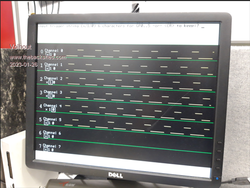 PicomiteVGA PETSCII ROBOTS |
||||
| Pluto Guru Joined: 09/06/2017 Location: FinlandPosts: 375 |
@Matherp. Re: your PIO assemble test program. PIO assmble test I updated to the latest firmware 5.07.07b10 and run the test again. I noticed still some problems with the delays. 'PIO assemble test.bas 'Test program from Matherp for testing of "PIO assemble" introduced in 'PicoMite MMBasic Version 5.07.07b10 PIO assemble 1,".program myprog" 'start the assembly PIO assemble 1,".line 0" PIO assemble 1,".side_set 1 opt pindirs" 'sideset=1 PIO assemble 1,"do_nack:" 'label= prog line 0 PIO assemble 1,"jmp y-- 12" 'prog line 0: &h008C PIO assemble 1,"irq wait 0 rel" 'prog line 1: &hC030 PIO assemble 1,"do_byte:" 'label=prog line 2 PIO assemble 1,"set x,7" 'prog line 2: &hE027 PIO assemble 1,"bitloop:" 'label=prog line 3 PIO assemble 1,"out pindirs,1 [7]" 'prog line 3: &h6781 PIO assemble 1,"nop side 1 [2]" 'prog line 4: &hBA42 (Delay=10)!!! PIO assemble 1,"wait 1 pin,1 [4]" 'progline 5:&h24A1 PIO assemble 1,"in pins,1 [7]" 'prog line 6:&h4701 PIO assemble 1,"jmp x-- bitloop side 0 [7]" 'prog line 7: &h1743 PIO assemble 1,"out pindirs, 1 [7]" 'prog line 8: &h6781 PIO assemble 1,"nop side 1 [7]" 'prog line 9: &hBF42 (delay=15)!!! PIO assemble 1,"wait 1 pin, 1 [7]" 'prog line 10: &h27A1 PIO assemble 1,"jmp pin do_nack side 0 [2]" 'prog line 11: &h12C0 PIO assemble 1,"entry_point:" 'label: PIO assemble 1,"out x,6" 'prog line 12: &h6026 PIO assemble 1,"out y,1" 'prog line 13: &h6041 PIO assemble 1,"jmp !x do_byte" 'prog line 14: &h0022 PIO assemble 1,"out null,32" 'prog line 15: &h6060 PIO assemble 1,"do_exec:" 'label=prog line 16 PIO assemble 1,"out exec,16" 'prog line 16: &h60F0 PIO assemble 1,"jmp x-- do_exec" 'prog line 17: &h0050 PIO assemble 1,".end program list" prog line 4: Delay is 10, but should be 2. Delay/sideset bits 11010 should be 10010. prog line 9: Delay is 15, but should be 7. delay/sideset bits 11111 should be 10111. /Pluto |
||||
| matherp Guru Joined: 11/12/2012 Location: United KingdomPosts: 10180 |
The delays are correct - checked against the official PIOASM What you are missing is the effect of the opt parameter on .sideset This sets the MSB of the delay/sideset field for every instruction in which "side" is used. It is this that tells the silicon that the "side" is to be applied to all subsequent instructions until the next explicit usage. It may have been mentioned in Volhout's notes but is certainly in the manual that when you use "opt" you lose a bit from delay/side_set. This is that bit  I don't know if the MMREPLACE plug-in supports "opt". If it does it should be tested for this. The Pico examples use "opt" quite a lot so this is important. Attached is the PIOASM output // -------------------------------------------------- // // This file is autogenerated by pioasm; do not edit! // // -------------------------------------------------- // #pragma once #if !PICO_NO_HARDWARE #include "hardware/pio.h" #endif // --- // // i2c // // --- // #define i2c_wrap_target 12 #define i2c_wrap 17 #define i2c_offset_entry_point 12u static const uint16_t i2c_program_instructions[] = { � �0x008c, // �0: jmp � �y--, 12 � � � � � � � � � � � �0xc030, // �1: irq � �wait 0 rel � � � � � � � � � �0xe027, // �2: set � �x, 7 � � � � � � � � � � � � �0x6781, // �3: out � �pindirs, 1 � � � � � � [7] � �0xba42, // �4: nop � � � � � � � � � �side 1 [2] � �0x24a1, // �5: wait � 1 pin, 1 � � � � � � � [4] � �0x4701, // �6: in � � pins, 1 � � � � � � � �[7] � �0x1743, // �7: jmp � �x--, 3 � � � � �side 0 [7] � �0x6781, // �8: out � �pindirs, 1 � � � � � � [7] � �0xbf42, // �9: nop � � � � � � � � � �side 1 [7] � �0x27a1, // 10: wait � 1 pin, 1 � � � � � � � [7] � �0x12c0, // 11: jmp � �pin, 0 � � � � �side 0 [2] � � � � � �// � � .wrap_target � �0x6026, // 12: out � �x, 6 � � � � � � � � � � � � �0x6041, // 13: out � �y, 1 � � � � � � � � � � � � �0x0022, // 14: jmp � �!x, 2 � � � � � � � � � � � � �0x6060, // 15: out � �null, 32 � � � � � � � � � � �0x60f0, // 16: out � �exec, 16 � � � � � � � � � � �0x0050, // 17: jmp � �x--, 16 � � � � � � � � � � � � � � � �// � � .wrap }; #if !PICO_NO_HARDWARE static const struct pio_program i2c_program = { � �.instructions = i2c_program_instructions, � �.length = 18, � �.origin = -1, }; static inline pio_sm_config i2c_program_get_default_config(uint offset) { � �pio_sm_config c = pio_get_default_sm_config(); � �sm_config_set_wrap(&c, offset + i2c_wrap_target, offset + i2c_wrap); � �sm_config_set_sideset(&c, 2, true, true); � �return c; } #include "hardware/clocks.h" #include "hardware/gpio.h" static inline void i2c_program_init(PIO pio, uint sm, uint offset, uint pin_sda, uint pin_scl) { � �assert(pin_scl == pin_sda + 1); � �pio_sm_config c = i2c_program_get_default_config(offset); � �// IO mapping � �sm_config_set_out_pins(&c, pin_sda, 1); � �sm_config_set_set_pins(&c, pin_sda, 1); � �sm_config_set_in_pins(&c, pin_sda); � �sm_config_set_sideset_pins(&c, pin_scl); � �sm_config_set_jmp_pin(&c, pin_sda); � �sm_config_set_out_shift(&c, false, true, 16); � �sm_config_set_in_shift(&c, false, true, 8); � �float div = (float)clock_get_hz(clk_sys) / (32 * 100000); � �sm_config_set_clkdiv(&c, div); � �// Try to avoid glitching the bus while connecting the IOs. Get things set � �// up so that pin is driven down when PIO asserts OE low, and pulled up � �// otherwise. � �gpio_pull_up(pin_scl); � �gpio_pull_up(pin_sda); � �uint32_t both_pins = (1u << pin_sda) | (1u << pin_scl); � �pio_sm_set_pins_with_mask(pio, sm, both_pins, both_pins); � �pio_sm_set_pindirs_with_mask(pio, sm, both_pins, both_pins); � �pio_gpio_init(pio, pin_sda); � �gpio_set_oeover(pin_sda, GPIO_OVERRIDE_INVERT); � �pio_gpio_init(pio, pin_scl); � �gpio_set_oeover(pin_scl, GPIO_OVERRIDE_INVERT); � �pio_sm_set_pins_with_mask(pio, sm, 0, both_pins); � �// Clear IRQ flag before starting, and make sure flag doesn't actually � �// assert a system-level interrupt (we're using it as a status flag) � �pio_set_irq0_source_enabled(pio, pis_interrupt0 + sm, false); � �pio_set_irq1_source_enabled(pio, pis_interrupt0 + sm, false); � �pio_interrupt_clear(pio, sm); � �// Configure and start SM � �pio_sm_init(pio, sm, offset + i2c_offset_entry_point, &c); � �pio_sm_set_enabled(pio, sm, true); } #endif // ----------- // // set_scl_sda // // ----------- // #define set_scl_sda_wrap_target 0 #define set_scl_sda_wrap 3 static const uint16_t set_scl_sda_program_instructions[] = { � � � � � �// � � .wrap_target � �0xf780, // �0: set � �pindirs, 0 � � �side 0 [7] � �0xf781, // �1: set � �pindirs, 1 � � �side 0 [7] � �0xff80, // �2: set � �pindirs, 0 � � �side 1 [7] � �0xff81, // �3: set � �pindirs, 1 � � �side 1 [7] � � � � � �// � � .wrap }; #if !PICO_NO_HARDWARE static const struct pio_program set_scl_sda_program = { � �.instructions = set_scl_sda_program_instructions, � �.length = 4, � �.origin = -1, }; static inline pio_sm_config set_scl_sda_program_get_default_config(uint offset) { � �pio_sm_config c = pio_get_default_sm_config(); � �sm_config_set_wrap(&c, offset + set_scl_sda_wrap_target, offset + set_scl_sda_wrap); � �sm_config_set_sideset(&c, 2, true, false); � �return c; } // Define order of our instruction table enum { � �I2C_SC0_SD0 = 0, � �I2C_SC0_SD1, � �I2C_SC1_SD0, � �I2C_SC1_SD1 }; #endif Edited 2023-01-26 19:11 by matherp |
||||
| Pluto Guru Joined: 09/06/2017 Location: FinlandPosts: 375 |
Thanks Peter! I missed the "opt". When you say it, I remember reading about it some time ago in RP2040 datasheet. Too many new things to learn in the last couple of weeks. I think my brain acts a ringbuffer. /Pluto |
||||
| Volhout Guru Joined: 05/03/2018 Location: NetherlandsPosts: 5021 |
@Peter, This is a summary of observations with picomite VGA. Not intended to direct in any direction, but just user experience that may be used, or can be discarded at will. 1/ The PS2 keyboard issue, and the error message in totally correct code where not reproducible. They may have been caused by a derailed DMA (my coding error). 2/ When using RAM (large arrays) and stopping the MMBasic program, you get a "out of memory" message when asking the starage system index (FILES). Even if the file system only contains 3 files (A://) and there is still 30k+ free. Work around: press F4 (edit) press <ESC> (exit) and you can see what is on the drive. 3/ When using tiles in a program using screen mode 1, stopping the program you are left with a colorfull paper/ink combination. A CLS will clean the screen, but not restore the tiles to default. Work around: press F4 and ESC. 4/ It would be nice if we had a way to save a mode1 screenshot including tiles colors. Just to publish on the forum. 5/ It would be nice to have a font that exectly lines up with the tiles in mode 1. I have tried, and did not find one in the current font set. Maybe it is easy by taking a slightly smaller font that already exists, and just modify the character pitch and line distance, and call that font #10 or so. Since we have 40x30 tiles, a 80x30 screen would be possible (2 characters per tile, line up nicely). Thank you for reading, Volhout Edited 2023-01-27 19:32 by Volhout PicomiteVGA PETSCII ROBOTS |
||||
| The Back Shed's forum code is written, and hosted, in Australia. | © JAQ Software 2025 |
