
|
|
Forum Index : Microcontroller and PC projects : DMX master on Pico ?
| Author | Message | ||||
| tom_g Newbie Joined: 21/02/2023 Location: SwitzerlandPosts: 20 |
Hi, has anyone realized the DMX master protocol in PIO on the Pico ? I need to address 10 channels in a single universe. There are several libraries for C, but I'd rather code in Basic. Thanks for your answer - Tom |
||||
| Frank N. Furter Guru Joined: 28/05/2012 Location: GermanyPosts: 1102 |
Hi Tom, not with the PicoMite, but in MMBASIC (that was already 10 years ago...): https://www.thebackshed.com/forum/ViewTopic.php?TID=4980 https://www.thebackshed.com/forum/ViewTopic.php?TID=5526 Frank |
||||
| tom_g Newbie Joined: 21/02/2023 Location: SwitzerlandPosts: 20 |
Thanks Frank, for the links, if ever I should need a serial-to-DMX gateway processor to build the timing I'd use the mighty old PSoC1 which I know very well. My intention was however to have RP2040 PIO to do the DMX timing. At date I have no knowledge yet how to program the PIO Anyone ? |
||||
| matherp Guru Joined: 11/12/2012 Location: United KingdomPosts: 11513 |
At date I have no knowledge yet how to program the PIO Check this thread from volhout - everything you need to know. See also this for PIO in action |
||||
| tom_g Newbie Joined: 21/02/2023 Location: SwitzerlandPosts: 20 |
Peter, I am tempted to dig into PIO, I feel the topic might be of some complexity... BTW the second link in your previous post does not lead into a thread, can you repost pls, tnx. It was Volhout who pointed out the feasability of hardware PWM with deadband in order to control high and low side MOSFETs in half bridge configuration. Getting to know this I gave RP2040 and PicoMite a try and I am really surprised how good this all works ! Actually my first application with Pico - and -Mite is a 1/2 kW step down DC power converter for an exhibt in our science center, with energy display and power generation bar by WS2812 LEDs I want to thank you and all of the contributors for your brilliant open source work alltogether ! - Tom |
||||
| Volhout Guru Joined: 05/03/2018 Location: NetherlandsPosts: 5931 |
hi tom_g, So what you need is a 250kbps UA(R)T that can generate a DMX BREAK, and send 8 bit data (LSB first) strings with 1 start, and 2 stop bits. According this: DMX That does not seem very hard to do. As long as there is no RDM requirement (return channel) we could use the PIO (in combination with the DMA when speed is relevant). But it maybe even do-able from MMBasic directly, since the time between bytes is not relevant (1 second max) and the break can be generated from basic on the same line, or, sending a UART character in a different baudrate that translates to 88us. Regards, Volhout PicomiteVGA PETSCII ROBOTS |
||||
| tom_g Newbie Joined: 21/02/2023 Location: SwitzerlandPosts: 20 |
Volhout, good to read your lines, tnx ! interbyte time is not critical in my application, so I'll think about your suggestion of using UART and additional BREAK gate pulse by software. I'll let the forum know about the progress. PIO implementation will be a challenge which I want to take, beginning with studying your tutorial. (application of DMX control here at science center: control of pressure of 10 DMX water jet pumps, each generating a smooth water jet overhead over our vistors head in clean parabolic shape. We must periodically fine adjust the pressure of each such as the landing zone of the jets remains in the corresponding drain channel. Presently the pumps and the water beam cutters are integrated in a proprietary DMX player and processing is very weary, that' why we want to control the pumps from our own environment ..) Best regards: Tom |
||||
| homa Guru Joined: 05/11/2021 Location: GermanyPosts: 627 |
This would be a good project to understand again the PIOs better and to come step by step to the DMX signal. @Volhout: Do you want to go through this with us? I would love to be there. Have unfortunately because of all the other activities VGA Pico with the son and the weather phenomenon WLAN Pico Alphas hardly had time for your super tutorial. BUT DMX would bait me immediately. DMX is somehow "time critical". The protocol does not send the higher addresses if empty or no change. Then you can start again with address 1 in the next frame. Therefore one packs the scanners / Movingheads also at the initial addresses and has quite gladly after a few scanners (depending upon channel need) also gladly a new universe for the further scanners. Then the devices react more directly and faster. Shouldn't a PicoMite be able to operate up to 4 DMX universes with the PIOs? That would be an extremely inexpensive thing! The memory would be 4 longstrings with 512 characters each. Each character a byte 0-255 for value representation. So 2048 bytes. These then over the PIOs to four different GP PINs send. Then still the DMX output circuit and ... i am dreaming :-) @Tom: On which mountain plateau may I admire that then ;-) On vacation in Austria, this was felt on every 5th mountain. @To both: Want to try this together with the PIOs? Matthias |
||||
| Volhout Guru Joined: 05/03/2018 Location: NetherlandsPosts: 5931 |
Hi Matthias, I am willing to support you with a DMX driver for PIO. But I am currently not in a position to spend the time to debug and I do not have any DMX device. What I can do is put you on a path (there are multiple paths to success, and this is what I think, the simplest one). The essence is the UA(R)T function in PIO. When you are not adding any other functionality to the PIO there is plenty of program space to dot it brute force. send_1_byte: PULL blocking 'this loads a value from FIFO into OSR, waits for new data SET GPx low 'start bit on GPx OUT GPx,1 'shift LSB to pin GPx OUT GPx,1 'shift bit 1 to pin GPx OUT GPx,1 'shift bit 2 to pin GPx OUT GPx,1 'shift bit 3 to pin GPx OUT GPx,1 'shift bit 4 to pin GPx OUT GPx,1 'shift bit 5 to pin GPx OUT GPx,1 'shift bit 6 to pin GPx OUT GPx,1 'shift MSB to pin GPx SET GPx high 'first stop bit JMP send_1_byte 'loop for second character, 2'nd stop bit pin does not change) If you configure the PIO clock to 250kHz, then this is the core UART transmit part at 250kbps. Each instruction is 4us. Before you can output data to the program the GPx pin an output, and generate the BREAK condition. init_break: SET PINDIRS,1 'set GPx output SET GPx low (dly=22) 'this is the break pulse at 22x4us = 88us SET GPx high (dly=1) 'this is the end of break, 8us wide So this is your complete PIO program. You need to add the GPx pin as the only pin to both the SET domain, and to the OUT domain for that particular state machine. So you need the PIO to be configured to: p=pinctrl 0,1,1,,,gpx,gpx 'where gpx = the pin you want to use, ie. gp0 shiftctrl 'default is okay execctrl 'default is okay f=250e3 'PIO clock 250kHz 'if you want to run the program on PIO 1 state machine 0 pio init machine 1,0,f,p,,,0 'start at address 0 How does this work in MMBasic ? Each time you update a DMX universe you have to - start the PIO, so it inits and sends the BREAK - start feeding up to 512 bytes to the FIFO with PIO WRITE 1,0,value% - wait a bit between each byte (more about this later) but you can start with PAUSE 0.1 (100us) - STOP PIO 1,0 (stop the state machine) - Re-init the state machine (PIO INIT MACHINE 1,0,f,p,,,0) so next time it starts at 0 (lable: init_break) again. In case you have this working, you can use the PIO DMA to automate stuff for you. The DMA will do the waiting between bytes, and start the machine for you. Assume you have XX bytes (max 512) in array DMX%(), the process will be Each time you want to update the universe PIO DMA TX 1,0,XX,DMX%(),I_am_done The PIO DMA will start the PIO, handle all the transfer, and when done, it will jump to I_am_done so you need a sub: SUB I_am_done PIO STOP 1,0 PIO INIT MACHINE 1,0,f,p,,,0 END SUB Good luck coding..... Edited 2023-02-23 19:38 by Volhout PicomiteVGA PETSCII ROBOTS |
||||
| Volhout Guru Joined: 05/03/2018 Location: NetherlandsPosts: 5931 |
@Matthias, In case you want to implement DMX master in a simple way (using pure MMBasic): 'test COM port 2 for DMX512 transmitter 'uses GP4 as TX pin and GP3 as BREAK generator 'requires external AND gate (74HC08) to combine GP3 and GP4 inot '1 signal to drive MAX485 driver chip. SetPin gp3,dout 'pin for BREAK generation Pin(gp3)=1 'default is high SetPin gp5,gp4,COM2 'open COM port (for TX only) Open "COM2:250000,S2" As #1 'at DMX speed DMX$="Hello" Do Pulse GP3,0.1 '100us break Print #1,DMX$ 'send data Pause 100 'pause for trigger Loop Above code will use pin GP3 to generate the BREAK signal, and GP4 (COM2) to transmit the strings. You have to combine the 2 signals in an AND gate (i.e. 74HC08, pin 1-GP3, pin2-GP4, pin3=DMXout). That may seem as a extra chip, but since you will have the add the MAX485 driver chip anyway, it is just 1 more chip on the breadboard. Waveform (100us BREAK) on my breadboard (sending string "Hello" at 250kbaud); 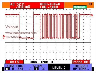 If you change the content of DMX$ to your liking, you should be ready with these few lines of code. Volhout Edited 2023-02-23 20:39 by Volhout PicomiteVGA PETSCII ROBOTS |
||||
| tom_g Newbie Joined: 21/02/2023 Location: SwitzerlandPosts: 20 |
Hi all, I am still stuck deep in Volhout's basic PIO lessons and now find two solutions prepared ... wow, surprise and thank you for this ultrafast action ! |
||||
| homa Guru Joined: 05/11/2021 Location: GermanyPosts: 627 |
@Volhout: You are top! Thanks for your help and suggestion of a solution. Your speed is splendid. At the moment I have a few birthday family parties ... Hardware is not a problem. DMX RGB spotlight, scanner, etc.. All available. Also an oscilloscope if needed. A circuit from GP pin to DMX I also still have, only need to check the levels ... 3.3Volt is all new, previously had everything on 5Volt. Is only hobby :-) I hope on the weekend a few hours to have time for the project. But it does not run away. Matthias |
||||
| tom_g Newbie Joined: 21/02/2023 Location: SwitzerlandPosts: 20 |
Hi all, this is my intermediate state in coding a DMX driver according to Volhout's suggestions. As Volhout stipulates, I will use DMA transfer for the DMX data instead of software in the next version. I must admit, PIO programming is not trivial nor very comfortable by now, I am missing PASM. Has it already an usable state and whre to get it from ? But thanks to Volhout's tutorial, which took considerable time to digest (even not yet fully...) I can use RP2040 datasheet and work with it as I overcame the respect barrier. Here's my first approach to tranmitting DMX bytes. ' PIO DMX demo driver, ' brute force style suggested by Volhout, tnx ! ' see thread https://www.thebackshed.com/forum/ViewTopic.php?FID=16&TID=15606 ' coded by tom_g - 230227 ' NOK on a PicoW with FW PicoMiteWeb V5.07.07a20 which resulted in reboot and loss of USB connection, reporting address error ' Was not able to use PIO1, -> does PicoW use PIO1 in FW ? ' OK using FW V5.07.06 with PicoW works for this application OPTION Explicit ' alle Variabeln muessen explizit deklariert werden OPTION Default NONE ' Variabeln typen muessen explizit deklariert werden Option Colorcode ON ' RP2040 inbuilt basic editor syntax colour highlighting ON Option Tab 4 ' Tabulator Abstand im inbuilt editor (indenting) OPTION AUTORUN ON ' start mit dieser Firmware aus dem flash ' gp0 assigned to PIO0 setpin gp0,pio0 'PIO configuration preset DIM p AS INTEGER = PIO(pinctrl 0,1,1,,,gp0,gp0) 'where gpx = the pin you want to use, ie. gp0 'shiftctrl 'default 'execctrl 'default DIM f AS INTEGER = 250e3 'PIO clock 250kHz 4us per cycle for DMX ' init pio program line 0,0,&hE081 'SET PINDIRS,1 1110 0000 1000 0001 = &hE081 pio program line 0,1,&hF600 'SET GP0 low (dly=22) 1111 0110 0000 0000 = &hF600 pio program line 0,2,&hE101 'SET GP0 high (dly=1) 1110 0001 0000 0001 = &hE101 ' send_a_byte pio program line 0,3,&h80A0 'PULL blocking 1000 0000 1010 0000 = &h80A0 pio program line 0,4,&hE000 'SET GP0 low 1110 0000 0000 0000 = &hE000 pio program line 0,5,&h6001 'OUT GP0,1 0110 0000 0000 0001 = &h6001 pio program line 0,6,&h6001 'OUT GP0,1 0110 0000 0000 0001 = &h6001 pio program line 0,7,&h6001 'OUT GP0,1 0110 0000 0000 0001 = &h6001 pio program line 0,8,&h6001 'OUT GP0,1 0110 0000 0000 0001 = &h6001 pio program line 0,9,&h6001 'OUT GP0,1 0110 0000 0000 0001 = &h6001 pio program line 0,10,&h6001 'OUT GP0,1 0110 0000 0000 0001 = &h6001 pio program line 0,11,&h6001 'OUT GP0,1 0110 0000 0000 0001 = &h6001 pio program line 0,12,&h6001 'OUT GP0,1 0110 0000 0000 0001 = &h6001 pio program line 0,13,&hE101 'SET GP0 high 1110 0001 0000 0001 = &hE101 pio program line 0,14,&h0003 'JMP send_a_byte 0000 0000 0000 0011 = &h0003 'init PIO 0 state machine 0 pio init machine 0,0,f,p,,,0 'start at address 0 ' citing Volhout: ' How does this work in MMBasic ? 'Each time you update a DMX universe you have to '- start the PIO, so it inits and sends the BREAK '- start feeding up to 512 bytes to the FIFO with PIO WRITE 1,0,value% '- wait a bit between each byte (more about this later) but you can start with PAUSE 0.1 (100us) '- STOP PIO 1,0 (stop the state machine) '- Re-init the state machine (PIO INIT MACHINE 1,0,f,p,,,0) so next time it starts at 0 (lable: init_break) again. 'In case you have this working, you can use the PIO DMA to automate stuff for you. (tom_g: at this stage now) ' tom_g: remains to do 'The DMA will do the waiting between bytes, and start the machine for you. 'Assume you have XX bytes (max 512) in array DMX%(), the process will be 'Each time you want to update the universe 'PIO DMA TX 1,0,XX,DMX%(),I_am_done CONST i_max = 12 DIM value%(i_max) AS INTEGER = (12,23,45,33,40,41,43,45,65,44,46,47,49) ' test data just for debugging DIM i AS INTEGER = 0 ' ---- 'main Do PIO START 0,0 PIO WRITE 0,0,1,value%(i) ' send a byte if (i < i_max) THEN i= i+1 else i= 0 PAUSE 10 '10ms interbyte delay for scope testing ENDif PAUSE 0.1 '100us PIO STOP 0,0 PIO INIT MACHINE 0,0,f,p,,,0 loop |
||||
| Volhout Guru Joined: 05/03/2018 Location: NetherlandsPosts: 5931 |
In picomite mmbasic v50707 the pio assembler is build in. So manually assembling the program is not needed anymore. So PASM is not required anymore. If you like developping in MMEdit, there os also an addon for it that can help you assembling the code for PIO. This is all quite recent stuff, the development triggered from the PIO training coarse. Some info about use of the build in pio assembler can be found in the release notes that are in the ZIP of each beta release. Volhout Edited 2023-02-28 07:10 by Volhout PicomiteVGA PETSCII ROBOTS |
||||
| JohnS Guru Joined: 18/11/2011 Location: United KingdomPosts: 4335 |
Do you mean pioasm (PIOASM if you prefer)? Apart from the already-posted, it's in the Pico SDK or on the web John |
||||
| The Back Shed's forum code is written, and hosted, in Australia. | © JAQ Software 2026 |
