
|
|
Forum Index : Microcontroller and PC projects : Design #3 - PicoMite VGA mini
| Page 1 of 5 |
|||||
| Author | Message | ||||
| Mixtel90 Guru Joined: 05/10/2019 Location: United KingdomPosts: 7815 |
I've kept going back to this for a while and this is the latest incarnation, Version 6. It still fits the same 90x70x28mm case from ebay etc. but now it has: Linear regulator by default. Volhout's auio filter. Choice of standard or micro SD card. A 2-colour LED (see below). > There are now no ebay modules used, it's all standard components. > The I/O connector has been reduced to 16 pins (8+8) as that uses up all available spare I/O on the PicoMite. This is a common size for ribbon cable. > The LED is two colour. GP22 can be switched to be used as an I/O pin or to control the green element of the LED. The red element is connected to 5V via a resistor by default (Power On indication) but this can be disconnected and a wire used to connect the TP directly to it. In this case it replaces the heartbeat LED on the PicoMite because its Vf is lower. > The PicMite has been rotated through 90 degrees, so its USB connector could be made accessible through the side of the case. To make this work it would be better to use shorter headers than usual. > Almost all the resistors are beneath the PicoMite to keep things compact, but they are reasonably well spaced apart. If the standard SD card option is used then it should be fairly easy to assemble by anyone who can solder. 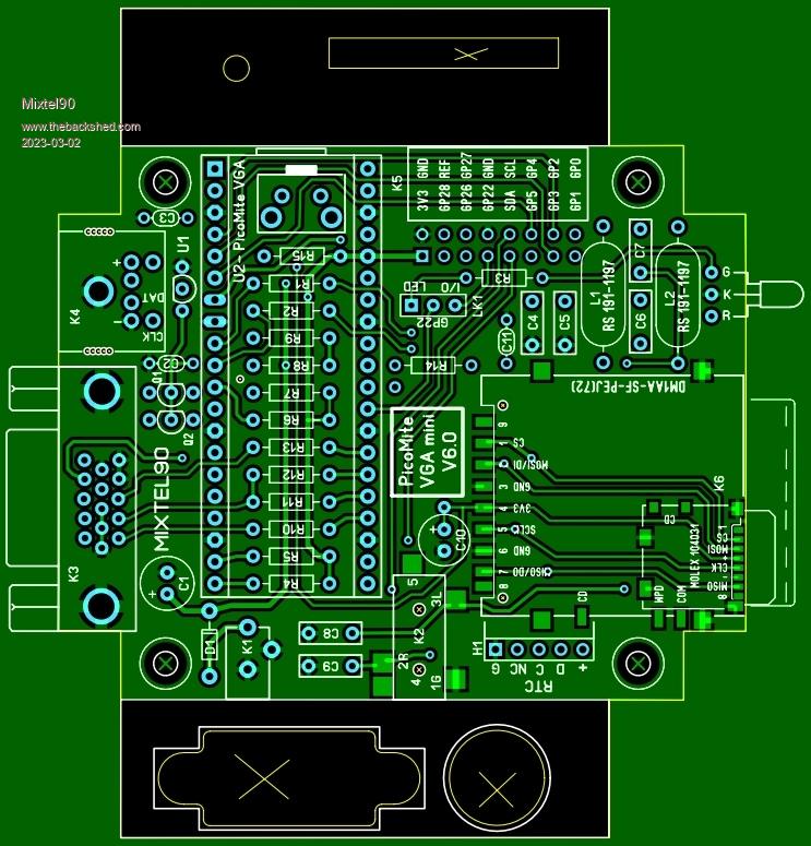 Mick Zilog Inside! nascom.info for Nascom & Gemini Preliminary MMBasic docs & my PCB designs |
||||
| JohnS Guru Joined: 18/11/2011 Location: United KingdomPosts: 4032 |
A time-warp board, judging by the silkscreen! Looks good. John |
||||
| atmega8 Guru Joined: 19/11/2013 Location: GermanyPosts: 724 |
Mick, schematic available? If so, would you ship one PCB to Germany? |
||||
| Mixtel90 Guru Joined: 05/10/2019 Location: United KingdomPosts: 7815 |
Coming up. :) I'll be doing a construction pack for this one, complete with Gerber files. The whole thing is on a single 100x100mm PCB, cheapest price from JLCPCB. It's probably cheaper for you to get your own made than it is for postage! Mick Zilog Inside! nascom.info for Nascom & Gemini Preliminary MMBasic docs & my PCB designs |
||||
PilotPirx Regular Member Joined: 03/11/2020 Location: GermanyPosts: 98 |
Great design, I would also be interested. What is used as the RTC?  |
||||
| Mixtel90 Guru Joined: 05/10/2019 Location: United KingdomPosts: 7815 |
It's the little square one with a yellow battery slung underneath. Common on ebay etc. This sort. Mick Zilog Inside! nascom.info for Nascom & Gemini Preliminary MMBasic docs & my PCB designs |
||||
| Geoffg Guru Joined: 06/06/2011 Location: AustraliaPosts: 3281 |
If it is OK with you I would like to add this to the construction pack on my website (plus schematic, parts list, etc). Geoff Geoff Graham - http://geoffg.net |
||||
| atmega8 Guru Joined: 19/11/2013 Location: GermanyPosts: 724 |
Dead Link! |
||||
| JohnS Guru Joined: 18/11/2011 Location: United KingdomPosts: 4032 |
here John |
||||
| atmega8 Guru Joined: 19/11/2013 Location: GermanyPosts: 724 |
Ok, every (not fake) DS3231 Module should work.. |
||||
| William Leue Guru Joined: 03/07/2020 Location: United StatesPosts: 405 |
Mixtel, I would be very glad to purchase a construction kit for this design! I am sure you will post when available. -Bill |
||||
| Mixtel90 Guru Joined: 05/10/2019 Location: United KingdomPosts: 7815 |
@Geoff No problem. It'll be ready soon. :) I'm not intending to make up kits, Bill. The components are quite reasonable to get and the PCBs are very cheap to have made. Kits work out expensive, especially when international postage costs have to be included for. I will be providing full constructional info. Mick Zilog Inside! nascom.info for Nascom & Gemini Preliminary MMBasic docs & my PCB designs |
||||
| JanVolk Senior Member Joined: 28/01/2023 Location: NetherlandsPosts: 234 |
This looks really good Mick. I have not yet been able to test the VGA software version because I run into the staggered pin assignment of a VGA connector. I mostly use breadboards with the RP2040 or Raspberry Pi Pico and this pcb meets my expectations. Could be a small problem and not just for me I think soldering the smd connections for the micro sd card? But a micro SD card print with pin connection row could be added to that in existing SD card space, such as this https://www.ebay.com/itm/201414997418 and then the pins at the bottom and are also on AliExpress readily available and work great with my plates. A row of extra bus pins for I2C for, for example, a small Oled screen or I2C sensors would be a nice addition. Jan |
||||
| Mixtel90 Guru Joined: 05/10/2019 Location: United KingdomPosts: 7815 |
You don't need the micro SD socket at all. In fact, you don't need either SD card socket for it to work. :) The standard SD card socket is actually quite easy to solder as it has locating pegs to hold it in position - as does the audio jack socket. I only included the micro SD card socket for my own use. You can, of course, fit the standard SD card socket and use a micro SD card adapter in it if you only have micro cards. :). I can't really add options to add anything else inside, but I'll have a look at addding a pair of I2C pads somewhere. Mick Zilog Inside! nascom.info for Nascom & Gemini Preliminary MMBasic docs & my PCB designs |
||||
| JanVolk Senior Member Joined: 28/01/2023 Location: NetherlandsPosts: 234 |
Mick, Almost all my boards have an external micro SD card slot for a safer feeling when an update comes and the option list and flash memory are deleted. But I do indeed agree that you no longer need an extra SD card with the new file system, where you have to follow the path properly. Jan |
||||
| Mixtel90 Guru Joined: 05/10/2019 Location: United KingdomPosts: 7815 |
I'm always happier to have an external SD card of some sort. It's far better for stuff like data logging (it's only a couple of seconds to transfer the card to a PC) and, if you are going to use the built-in editor, you really need one for backups. Something I learned to my cost many years ago is that you need at least two copies of everything that isn't trivial. Mick Zilog Inside! nascom.info for Nascom & Gemini Preliminary MMBasic docs & my PCB designs |
||||
| Mixtel90 Guru Joined: 05/10/2019 Location: United KingdomPosts: 7815 |
Quite a major re-hash, hence the delay. :) Many of the changes are subtle, but there are some pretty obvious ones. 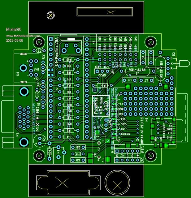 Edited 2023-03-08 01:09 by Mixtel90 Mick Zilog Inside! nascom.info for Nascom & Gemini Preliminary MMBasic docs & my PCB designs |
||||
| PilotPirx Regular Member Joined: 03/11/2020 Location: GermanyPosts: 98 |
Looks a bit confusing now. What are the extra holes for? Experimental field? Does it make sense to do without an external voltage regulator? With the SD card, RTC and LED, it can add up to a few mA. |
||||
| Mixtel90 Guru Joined: 05/10/2019 Location: United KingdomPosts: 7815 |
The "sea of holes" is for you to play with if you decide to use the micro SD card or neither. The external linear regulator is completely optional. It will be used by default but you are free to use the SMPS if you prefer (but there will be noise on the audio). There is enough spare current for the RTC and SD card. The LED is only running at 3-4mA for each colour. Just a bit of explanation of the changes. I rotated one of the inductors to get rid of magnetic coupling between them, reducing crosstalk between channels. I've been asked in the past about including a "sea of holes" in my designs for those who like to experiment. As the SD cards are no longer as important as they used to be I decided to steal some of that board space. I spread Q1 and Q2 out a bit to make assembly easier. Having R15 offset from the others annoyed me. That led to some rearrangement of the resistors, together with getting rd of a couple of layout idiocies. Pads have been added to access the I2C bus from inside the case. They may be useful for something. Mick Zilog Inside! nascom.info for Nascom & Gemini Preliminary MMBasic docs & my PCB designs |
||||
| JanVolk Senior Member Joined: 28/01/2023 Location: NetherlandsPosts: 234 |
Mick, Good progress and now becoming a universal print with many possibilities. I've been fitting and measuring with my SD card holder. If I want to mount the SD pcb of (18x18) directly on the PCB then L1 is in the way, but that can be remedied by placing the pin holder between the PCBs or L1 at the bottom of the PCB? Are the various separate islands fully metalised? And the lettering at the components could be a bit better like d g s or Inp gnd Out and a k and I haven't figured out yet what the part is under Raspberry Pi Pico at usb? And I've looked at the schematic, which hasn't been updated yet for this pcb, so it's not easy to check, but I don't think it's the final version yet and well on its way? Jan |
||||
| Page 1 of 5 |
|||||
| The Back Shed's forum code is written, and hosted, in Australia. | © JAQ Software 2025 |
