
|
|
Forum Index : Electronics : Bryan's 150V 45 A MTTP
| Author | Message | ||||
| poida Guru Joined: 02/02/2017 Location: AustraliaPosts: 1392 |
Bryan good to see a reason why. It did seem to be no ground connection to the sensor data after I had a sleep on it. I was getting worried how else I could help, apart from tracing Vin signal from the voltage divider to the A0 pin on the nano. Then finally proving ground was intact. Do not be concerned about high input voltages. The mppt works really well when input voltage is 2x output. This will ensure the panels are operating near max power point AND the DC-DC step down conversion is nearly optimal efficient too. My home setup has open circuit about 100V, max power about 80 to 85V and the battery goes from 47V to 54V. I expect it to be about 95% efficient. wronger than a phone book full of wrong phone numbers |
||||
Bryan1 Guru Joined: 22/02/2006 Location: AustraliaPosts: 1213 |
Hi Poida I just put my panels in series for 3 strings and the open circuit voltage was a tad over 40 volts, so connected the input power back on and the input power was drawn down to the battery voltage and it just stays in night mode. So getting close but still no banana's Cheers Bryan |
||||
| KeepIS Guru Joined: 13/10/2014 Location: AustraliaPosts: 1401 |
Just having a quick read and I think you are running a 24V system? If so, you may have better luck putting the panels in parallel, OC of 40 volts means an MPP somewhere around 33V? which is plenty for a 24V system going up to 30V. If I read this incorrectly please ignore. . It's all too hard. Mike. |
||||
| Bryan1 Guru Joined: 22/02/2006 Location: AustraliaPosts: 1213 |
KeepIs I did have those 6 panels all in parallel and noway would it get out of nite mode thats why I quickly wired up 2 in series for 3 banks of panels and when connected the input voltage dropped to the same as before. In the morning I'll wire up 3 in series to see if I can get a much higher input voltage as it has been mentioned having the input voltage twice the output for the best results. I'm going to have another look at the code to find where nite mode kicks in to understand it better as this is one huge learning curve for me. Cheers Bryan |
||||
| KeepIS Guru Joined: 13/10/2014 Location: AustraliaPosts: 1401 |
Have you measured the current that the batteries are actually trying to draw? Assuming favorable solar conditions, the only reason the panel output would fall to Vbat is when charge current is greater than the Panels can supply to the batteries, a bad connection to the panels, or a fault in the controller, but a fault would become apparent rather quickly if the panels were previously tested in parallel and the controller itself was the cause. Just throwing a few thing out there, you may have checked these already, hope you get it sorted soon, should be great once it's running correctly. Cheers . It's all too hard. Mike. |
||||
| Murphy's friend Guru Joined: 04/10/2019 Location: AustraliaPosts: 602 |
Bryan, are you waiting too impatiently  ? When in nite mode it takes 60 seconds to start up after it got sun power, you can see the numbers in the bottom right corner counting. ? When in nite mode it takes 60 seconds to start up after it got sun power, you can see the numbers in the bottom right corner counting.Poida might explain that feature better. |
||||
| Bryan1 Guru Joined: 22/02/2006 Location: AustraliaPosts: 1213 |
Mate my shed battery is a 24 volt 735AH forklift traction battery and it's been powering my shed for well over 10 years now. Looking at the sg and the battery is just over 3/4's charged ( well 24 on the scale is charged and it's on 21). On sunny days when I haven't used much power I can hear the batteries bubbling away so I just throw my beer fridge on and that keeps the voltage in check. My shed array hasn't had a controller on for well over a decade as it wasn't needed but with me putting more panels up well it might be time to make one. My goal is to get this first MTTP all sorted as I want to upgrade the house array and the MTTP will be put on those 20 year old kaneka panels which will free up a outback FM60 MTTP for the new panels. For my machineshop I went from using a 3 phase genset to VFD's and never looked back as the variable speed and programming to get the best out of the motor is a dream to use. So any sign of chatter just change the frequency and the chatter is gone, the best part the current draw under full load is well under 10 amps. Cheers Bryan |
||||
| KeepIS Guru Joined: 13/10/2014 Location: AustraliaPosts: 1401 |
Ah, well then, it looks like you have it all in hand and the problem is elsewhere. Sound like you are close to success. Cheers. It's all too hard. Mike. |
||||
| Bryan1 Guru Joined: 22/02/2006 Location: AustraliaPosts: 1213 |
OK new day and 170 watts coming in and still nite mode  saw a glimpse of 10 amps coming in too so something isn't right. Will leave it going and hopefully it soon wake up. saw a glimpse of 10 amps coming in too so something isn't right. Will leave it going and hopefully it soon wake up. |
||||
| mab1 Senior Member Joined: 10/02/2015 Location: United KingdomPosts: 175 |
It sounds to me like there's a short across the mosfets (or they're shorted themselves. Or permanently turned on). So as soon as the panels are connected they get pulled down to battery voltage. |
||||
| Bryan1 Guru Joined: 22/02/2006 Location: AustraliaPosts: 1213 |
Just put the probe on the TLP250 and pin 1-4 are all gnd where the right side is Vbat, now R1 is at gnd so no power going in from U1. With the fets the gate is at gnd the source on Vbat and the drain on gnd so to me the fets are not even turned on. Also I did change fets after that spark with my dmm probe. Edited 2023-06-08 10:15 by Bryan1 |
||||
| mab1 Senior Member Joined: 10/02/2015 Location: United KingdomPosts: 175 |
Ok, good, so there's no turn on signal from the brainboard. That sounds right. Not what I was expecting:- For the fets (q1 - q3), i would expect drains to be at solar+, the sources to be at bat+, and with no signal to turn them on from the tlp250, the gates should also be at bat+ For the 'diodes' (q4, q5), i would expect the centre leg (labelled d) to be at bat+, and the other two (g and s) at ground. All voltages measured relative to ground ( ground, bat negative , pv negative, all being the same). |
||||
| Bryan1 Guru Joined: 22/02/2006 Location: AustraliaPosts: 1213 |
Hi Mab, I just checked the fet voltages and yes they correspond with what you wrote  Now looking the aborb, float and eq settings and the switch threshold is 0.5 volts and if the nite threshold is the same that is the cause of my problem as the voltage difference on my setup is 0.3-0.4 volts. Cheers Bryan |
||||
| mab1 Senior Member Joined: 10/02/2015 Location: United KingdomPosts: 175 |
Ok, good... except: If the voltages are as i wrote (specifically, the gates of q1 - q3 are at the same voltage as the sources (bat+)), then the fets are turned off. Therefore the drains of q1 - q3 (solar+) should be at the open circuit voltage of the panels (40v? Did you say?), NOT near bat+ . So it does still look to me as if you have either a shorted fet or a short from drain to source across q1 - q3. |
||||
disco4now Guru Joined: 18/12/2014 Location: AustraliaPosts: 844 |
Bryan, Maybe a silly question, but do you have the FETs and Diodes isolated from the heat sink. The MPPT needs to be isolated, unlike the Inverter which can be mounted directly onto the three separate heat sinks. Gerry Latest F4 Latest H7 |
||||
| Bryan1 Guru Joined: 22/02/2006 Location: AustraliaPosts: 1213 |
Good point Gerry as I did use M3 countersunk screws they could be making contact with the heatsink. It's an easy fix as I do have a heap of that white tape that is used to put behind the fets so I'll cut some disks out with my hole puncher then a 3mm hole in the centre then lightly tighten the M3 countersunk bolt. Coffee is needed first then a quick test with my fluke 865 scope meter will let me know if the heatsink is at Vbat. Cheers Bryan |
||||
| Bryan1 Guru Joined: 22/02/2006 Location: AustraliaPosts: 1213 |
G'Day Guy's, Well I reckon I finally got membership in the blown fet club  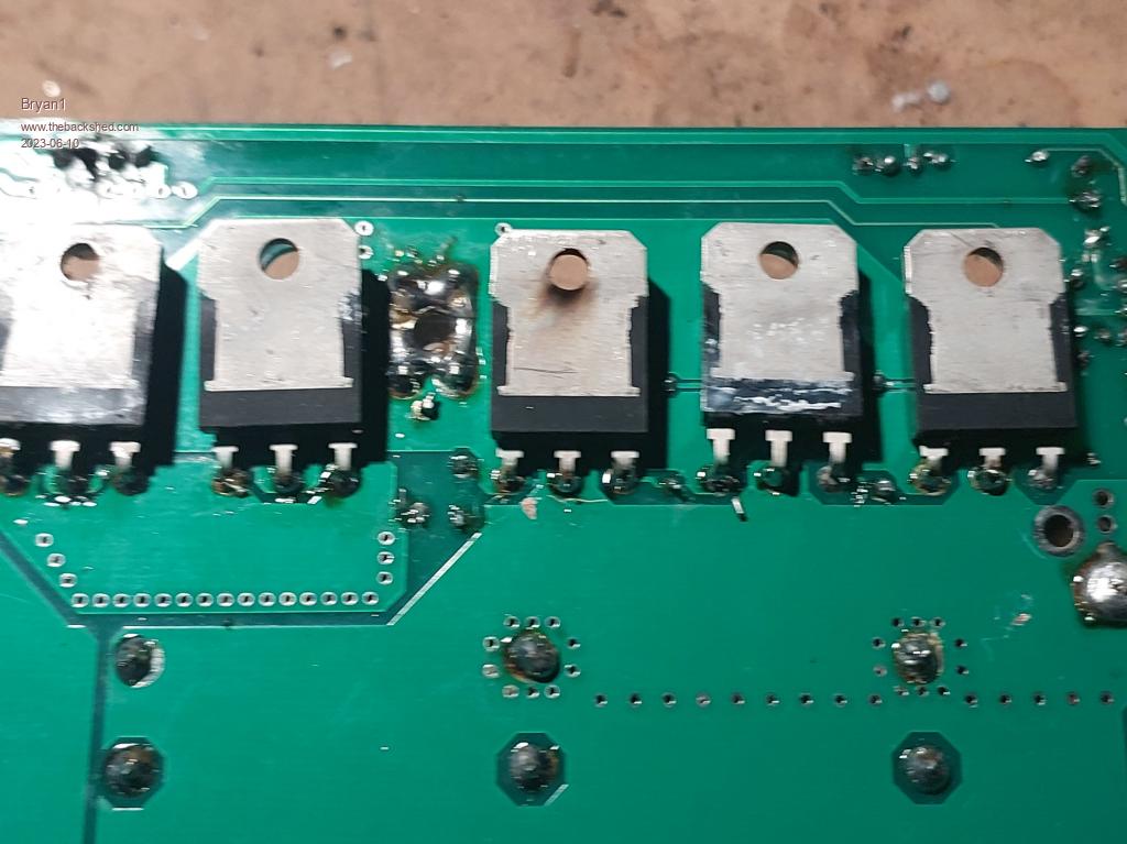 So fitted all new fets and carefully checked they were isolated and machined up plastic inserts for the fet holes so the screw couldn't touch the fet and short out. Got all setup again and eh Roger lets make a time mate as one problem is solved another is standing out no current 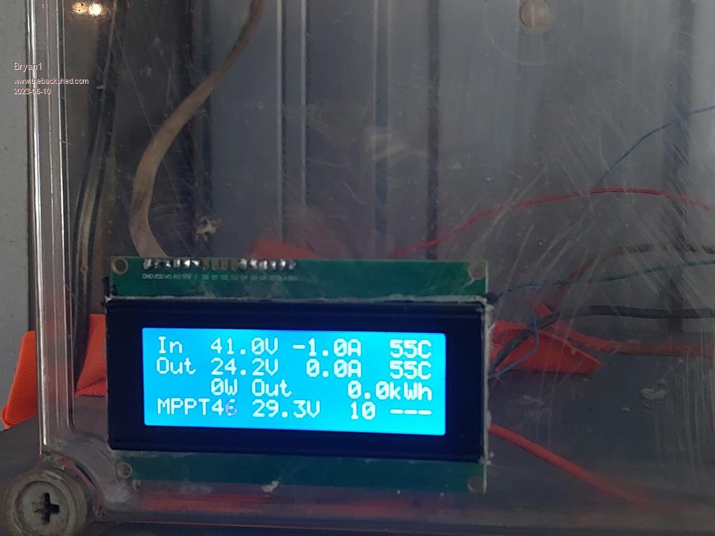 Saw 80 volts coming but no current so changed it back all parallel and no change to the current. Probed the incoming side of R1 and no voltage present. Cheers Bryan |
||||
| Ziki_the Newbie Joined: 13/04/2023 Location: YugoslaviaPosts: 28 |
Temp is 55c, is that ok with setings? Try to recalibrate current/voltage setings. Edited 2023-06-10 14:50 by Ziki_the Pozdrav iz Srbije |
||||
| Bryan1 Guru Joined: 22/02/2006 Location: AustraliaPosts: 1213 |
Zizi everything was calibrated and this is the first time it did show the open circuit voltage. I've now hooked it up to my 12volt array and I'm using my 30 volt 3amp power supply as the input. It is showing 30 volts in and 12.35 volts out but it has gone into NITE mode, the power also has the current set to max but the board doesn't want to take the current as both the lcd on the power supply and LCD shows zero. With the R13 12-12 chip the exposed holes on each side of the chip are showing VBat now the TLP250 is at ground on the left and Vbat on the right. |
||||
| Ziki_the Newbie Joined: 13/04/2023 Location: YugoslaviaPosts: 28 |
For current calibration you need to put current only to hall senzor, not the board input. First zero current, then 3A from your power supply. If you did that, then maybe you have some other problem. Pozdrav iz Srbije |
||||
